2017 MITSUBISHI LANCER Roof
[x] Cancel search: RoofPage 112 of 385

Sunroof (if so equipped)
Features and controls 5-47
5
If a hand or head is trapped in the closing sunroof opening, the safety mechanism willcause the sunroof to re-open automatically. The opened sunroof will become operational again after a few seconds.If the safety mechanism is activated 5 or more times consecutively, normal closing of the sunroof will be aborted.As an emergency measure, the sunroof can beclosed in small increments until it is com- pletely closed by repeatedly pressing the switch (2).After performing the emergency measure, consult an authorized Mitsubishi Motors dealer.
The sunshade can be opened or closed manu- ally while the sunroof is closed. When the sunroof is opened, the sunshade will also open automatically.
Safety mechanism
NOTE
The safety mechanism can be activated if the driving conditions or other circumstances cause the sunroof to be subjected to a physi-cal shock similar to that caused by a trapped hand or head.CAUTION The safety mechanism is deactivated just before the sunroof closes. This allows the sunroof to close completely. Therefore beespecially careful that fingers are not trapped in the sunroof opening.
The safety mechanism is deactivated while the switch (2) is pressed. Therefore be espe- cially careful that fingers are not trapped in the sunroof opening. Do not deliberately trap your hands or head in order to activate the safety mechanism. Personal injury and malfunction of the sun-roof could result.
Sunshade
CAUTION Do not attempt to close the sunshade when the sunroof is opened.CAUTION
Be careful that hands are not trapped when closing the sunshade.NOTE
Be sure to tilt down the sunroof before clos- ing the sunshade. When leaving the vehicle unattended, be sure to close the sunroof and without the ignition key. Do not try to operate the sunroof if it is fro- zen closed (after snowfall or during extreme cold). Do not sit on or place heavy luggage on the sunroof or roof opening edge. Do not apply any force that may cause dam- age to the sunroof. Release the switch when the sunroof has reached a completely open or completelyclosed position. If the sunroof does not operate when the sun- roof switch is operated, release the switch and check whether something is trapped by the sunroof. If nothing is trapped, have thesunroof checked at an authorized Mitsubishi Motors dealer. Be careful when tilting
up the sunroof if a ski
carrier or a roof carrier is installed. Depend-ing on the model of ski car
rier or roof carrier,
the sunroof may contact the carrier when the sunroof is tilted up.CAUTION
BK0237700US.bo
ok 47 ページ 2016年4月15日 金曜日 午前11時28分
Page 113 of 385

Parking brake 5-48 Features and controls
5
N00511401439
To park the vehicle, first bring it to a com- plete stop and fully engage the parking brake.For vehicles with a manual transaxle, move the gear shift lever to 1st (on a uphill) or “R” (Reverse) (on a downhill) position.For vehicles with a continuously variable transmission (CVT), set the selector lever to “P” (PARK) position.
When parking on a hill, apply the parking brake and turn the front wheels toward thecurb on a downhill grade, away from the curb on an uphill grade.
Be sure to close the sunroof completely when washing the vehicle or when leaving the vehicle. Do not put any wax on the weatherstrip (black rubber) around the sunroof opening. If it is waxed, the weatherstrip cannot maintain a weatherproof seal with the sunroof. After washing the vehicle or after rain be sure to wipe off any water that is on the sun-roof before operating it. Operating the sunroof repeatedly with the engine turned off will run down the battery. Operate the sunroof only while the engine is running.
Parking brake
NOTE
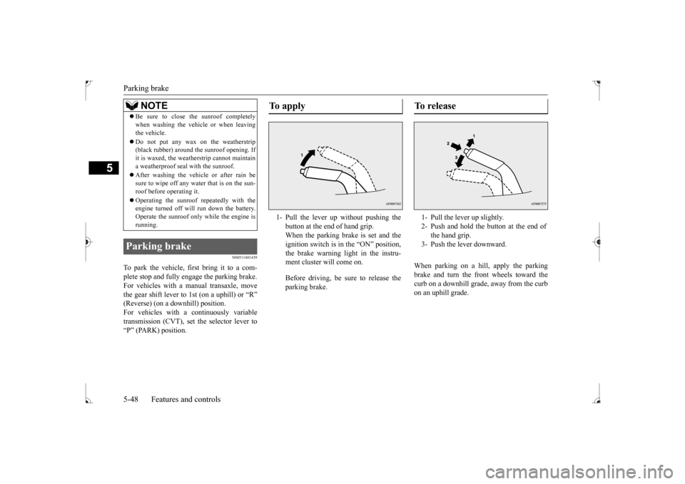
To apply 1- Pull the lever up without pushing the
button at the end of hand grip. When the parking brake is set and theignition switch is in the “ON” position, the brake warning light in the instru- ment cluster will come on. Before driving, be sure to release the parking brake.
To r e l e a s e 1- Pull the lever up slightly. 2- Push and hold the button at the end of
the hand grip.
3- Push the lever downward.
BK0237700US.bo
ok 48 ページ 2016年4月15日 金曜日 午前11時28分
Page 241 of 385

Loading information 6-6 Driving safety
6
Your front bumper can be damaged if you scrape it over curbs or parking stop blocks.Be careful when traveling up or down steep slopes where your bumper can scrape the road. When leaving the vehicle unattended, always carry the key and lock all doors.Always try to park your vehicle in a well lit area.
N00629900349
It is very important to know how much weight your vehicle can carry. This weight iscalled the vehicle capacity weight and includes the weight of all occupants, cargo and non-factory-installed options. The tireand loading information placard located on the driver’s door sill of your vehicle will show how much weight it may properly carry. It is important to familiarize yourself with the following terms before loading your vehicle: Vehicle maximum load on the tire: load on an individual tire that is determined by distributing to each axle its share of the maximum loaded vehicle weight anddividing by two. Vehicle normal load on the tire: load on an individual tire that is determined by dis-tributing to each axle its share of the curb weight, accessory weight, and normal occupant weight and dividing by two.
Maximum loaded vehicle weight: the sum of - (a) Curb weight; (b) Accessory weight;(c) Vehicle capacity weight; and (d) Production options weight. Curb weight: the weight of a motor vehi- cle with standard equipment including the maximum capacity of fuel, oil, and cool- ant. Accessory weight: the combined weight (in excess of those standard items which may be replaced) of automatic transmis- sion, power steering, power brakes, powerwindows, power seats, radio, and heater, to the extent that these items are available as factory- installed equipment (whetherinstalled or not). Vehicle capacity weight: the rated cargo and luggage load plus 150 lbs (68 kg)
*
times the vehicle’s designated seating capacity. Production options weight: the combined weight of those installed regular produc- tion options weighing over 5 lbs (2.3 kg) in excess of those standard items whichthey replace, not previously considered in curb weight or accessory weight, includ- ing heavy duty brakes, ride levelers, roofrack, heavy duty battery, and special trim.
WA R N I N G Leaving the engine running risks injury or death from accidentally moving the gear- shift lever (manual transaxle or the selec- tor lever (CVT) or from the accumulation of toxic exhaust fumes in the passengercompartment.
Where you park
WA R N I N G Do not park your vehicle in areas where combustible materials such as dry grass or leaves can come in contact with a hotexhaust, since a fire could occur.
When leaving the vehicle
Loading information
WA R N I N G Never overload your vehicle. Overloading can damage your vehicle, adversely affectvehicle performance, including handling and braking, cause tire failure, and result in an accident.
BK0237700US.bo
ok 6 ページ 2016年4月15日 金曜日 午前11時28分
Page 242 of 385

Loading information Driving safety 6-7
6
Normal occupant weight: 150 lbs (68 kg)
*
times the number of specified occupants. (In your vehicle the number is 3) Occupant distribution: distribution of occupants in a vehicle as specified. (In your vehicle the distribution is 2 in front, 1 in second row seat)
N00630100309
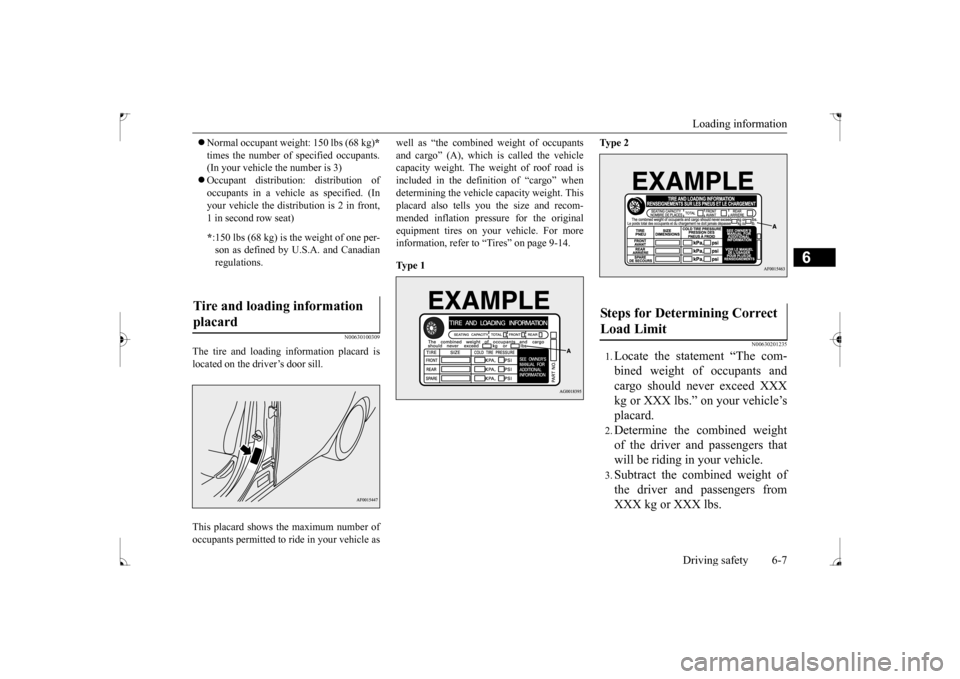
The tire and loading information placard islocated on the driver’s door sill. This placard shows the maximum number of occupants permitted to ride in your vehicle as
well as “the combined weight of occupants and cargo” (A), which is called the vehicle capacity weight. The weight of roof road is included in the definition of “cargo” whendetermining the vehicle capacity weight. This placard also tells you the size and recom- mended inflation pressure for the originalequipment tires on your vehicle. For more information, refer to “Tires” on page 9-14. Ty p e 1
Ty p e 2
N00630201235
1.Locate the statement “The com- bined weight of occupants and cargo should never exceed XXX kg or XXX lbs.” on your vehicle’splacard.2.Determine the combined weightof the driver and passengers thatwill be riding in your vehicle.3.Subtract the combined weight ofthe driver and passengers fromXXX kg or XXX lbs.
* :150 lbs (68 kg) is the weight of one per- son as defined by U.S.A. and Canadian regulations.
Tire and loading information placard
Steps for Determining Correct Load Limit
BK0237700US.bo
ok 7 ページ 2016年4月15日 金曜日 午前11時28分
Page 245 of 385

Cargo loads 6-10 Driving safety
6
N00629700464
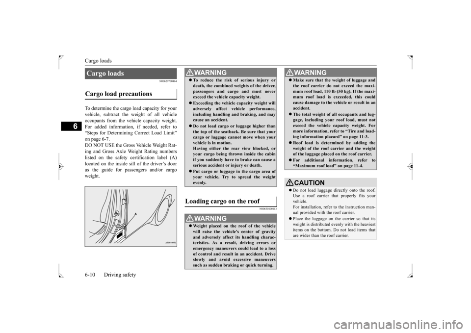
To determine the cargo load capacity for your vehicle, subtract the weight of all vehicleoccupants from the vehicle capacity weight. For added information, if needed, refer to “Steps for Determining Correct Load Limit”on page 6-7.DO NOT USE the Gross Vehicle Weight Rat- ing and Gross Axle Weight Rating numbers listed on the safety certification label (A)located on the inside sill of the driver’s door as the guide for passengers and/or cargo weight.
N00630400113
Cargo loads Cargo load precautions
WA R N I N G To reduce the risk of serious injury or death, the combined weights of the driver, passengers and cargo and must never exceed the vehicle capacity weight. Exceeding the vehicle capacity weight will adversely affect vehicle performance, including handling and braking, and maycause an accident. Do not load cargo or luggage higher than the top of the seatback. Be sure that your cargo or luggage cannot move when your vehicle is in motion.Having either the rear view blocked, or your cargo being thrown inside the cabin if you suddenly have to brake can cause aserious accident or injury or death. Put cargo or luggage in the cargo area of your vehicle. Try to spread the weight evenly.
Loading cargo on the roof
WA R N I N G Weight placed on the roof of the vehicle will raise the vehicle’s center of gravity and adversely affect its handling charac-teristics. As a result, driving errors or emergency maneuvers could lead to a loss of control and result in an accident. Driveslowly and avoid excessive maneuvers such as sudden braking or quick turning.
Make sure that the weight of luggage and the roof carrier do not exceed the maxi- mum roof load, 110 lb (50 kg). If the maxi- mum roof load is exceeded, this could cause damage to the ve
hicle or result in an
accident. The total weight of all occupants and lug- gage, including your roof load, must not exceed the vehicle capacity weight. For more information, refer to “Tire and load-ing information placard” on page 11-3. Roof load is determined by adding the weight of the roof carrier and the weight of the luggage placed on the roof carrier. For additional information, refer to “Maximum roof load” on page 11-4.CAUTION Do not load luggage directly onto the roof. Use a roof carrier th
at properly fits your
vehicle. For installation, refer to the instruction man- ual provided with the roof carrier. Place the luggage on the carrier so that its weight is distributed evenly with the heaviest items on the bottom. Do not load items that are wider than the roof carrier.WA R N I N G
BK0237700US.bo
ok 10 ページ 2016年4月15日 金曜日 午前11時28分
Page 246 of 385

Trailer towing
Driving safety 6-11
6
N00630600102
When installing the roof carrier, use the brackets (A). The brackets (A) are located under each cover (B).
Slide each cover (B) toward the front of the vehicle to remove it.
1. With each cover, put the tabs (C) on the cover in the holes (D) in the roof. 2. Slide the cover (B) toward the rear of thevehicle to install it.
N00629801332
Before driving and after traveling a short dis- tance, always check the load to make sure it is securely fastened to the roof carrier. Stop the vehicle periodically and check that the load remains secure. If the load is notsecure, it could fall from the vehicle and damage your vehicle, another vehicle or cre- ate a road hazard.NOTE
To prevent wind noise or reduction in gas mileage, remove the roof carrier when not in use. Before using an automatic car wash, check with the attendant to determine if the roof carrier should be removed. Be sure that adequate clearance is main- tained for raising the sunroof when installinga roof carrier. (For vehicle with sunroof only)
Roof carrier mounting brackets
(if so equipped)
CAUTION
Attaching the roof carrier
Refitting the covers
Trailer towing
BK0237700US.bo
ok 11 ページ 2016年4月15日 金曜日 午前11時28分
Page 298 of 385

Antenna
Comfort controls 7-51
7
N00734200426
Turn the pole (A) counterclockwise. Screw the pole (A) clockwise into the base (B) until it is securely retained.
For securing the best satellite reception, the angle of the antenna is fixed.
The disc cannot be inserted.
A disc is already in the product. Eject the disc.
“Insert/Eject Discs” (P.7-25)
There is no disc in the product, but the prod- uct says it is loading.
Press the eject button once. “Insert/Eject Discs” (P.7-25)
The disc cannot be played. The disc is inserted upside down. Insert with the label side up.
The disc has condensation on it. Wait a while before inserting.The disc is dirty. Clean the read surface of the disc.
The sound skips in the same place.
The disc is damaged or dirty. Check the disc.
There is no sound, even if the disc is inserted.
Damage to or dirt on the disc means that its data cannot be read.
Check the disc. Additionally, if using CD-R/RW discs, their charac- teristics may render them unable to be played.
Symptoms
Cause
Response
Antenna Roof antenna (except for vehi- cles with SIRIUS satellite radio) To remove To install
NOTE
Be sure to remove the roof antenna in the following cases: • When using an automatic car wash
• When covering your vehicle with a car cover • When driving into a structure that has a low ceiling
Roof antenna (for vehicles with SIRIUS satellite radio)
NOTE
BK0237700US.bo
ok 51 ページ 2016年4月15日 金曜日 午前11時28分
Page 299 of 385

Clock (if so equipped) 7-52 Comfort controls
7
Turn the pole (A) counterclockwise. Screw the pole (A) clockwise into the base (B) until it is securely retained.
N00755001219
The time is displayed when the ignitionswitch is in ON or ACC.
1. Press and hold the PAGE key until the clock display flashes.2. Press the various keys to adjust. 3. Press the PAGE key to finish adjusting the time. When the adjustment is complete, the clock display stops flashing.
To remove To i n s t a l l
NOTE
Be sure to remove the roof antenna in the following cases: • When entering a place with low clearance • When using an automatic car wash • When covering your vehicle with a car cover
Clock
(if so equipped)
NOTE
Reset the time after the battery terminals are disconnected and reconnected.
Time Setting
H - “Hour” setting
Press this key to fast-forward the“hours”.
M - “Minutes” setting
Press this key to fast-forward the “minutes”.
NOTE
If the PAGE key is pressed and held when the time adjustment is finished, the seconds will be reset to “00”.
PA G E /SEL
M
H
BK0237700US.bo
ok 52 ページ 2016年4月15日 金曜日 午前11時28分