2017 MERCEDES-BENZ S-Class MAYBACH key
[x] Cancel search: keyPage 330 of 382
XStop the vehicle on solid, non-slippery and
level ground, as far away as possible from
traffic.
XSwitch on the hazard warning lamps.
XSecure the vehicle against rolling away
(Ypage 162).
XIf possible, bring the front wheels into the
straight-ahead position.
XSwitch off the engine.
XOpen the driver's door.
The on-board electronics now have status0.
This is the same as the SmartKey having been
removed.
XRemove the Start/Stop button from the igni-
tion lock (Ypage 145).
or, if the SmartKey is inserted in the ignition
lock:
XRemove the SmartKey from the ignition lock.
XMake sure that the engine cannot be started
via your smartphone (Ypage 147).
XMake sure that the passengers are not endan-
gered as they do so. Make sure that no one is
near the danger area while a wheel is being
changed. Anyone who is not directly assisting
in the wheel change should, for example,
stand behind the barrier.
XGet out of the vehicle. Pay attention to traffic
conditions when doing so.
XClose the driver's door.
MOExtended tires (tires with run-flat
properties)
General notes
With MOExtended tires (tires with run flat char-
acteristics), you can continue to drive your vehi-
cle even if there is a total loss of pressure in one
or more tires. The affected tire must not show
any clearly visible damage.
You can recognize MOExtended tires by the
MOExtended marking which appears on the
sidewall of the tire. You will find this marking
next to the tire size designation, the load-bear-
ing capacity and the speed index (
Ypage 357).
MOExtended tires may only be used in conjunc-
tion with an active tire pressure loss warning
system or with an active tire pressure monitor. If a pressure loss warning message appears
in the multifunction display:
Robserve the instructions in the display mes-
sages (Ypage 252).
Rcheck the tire for damage.
Rif driving on, observe the following notes.
The driving distance possible in run-flat mode is
approximately 50 miles (80 km) when the vehi-
cle is partially laden. When the vehicle is fully
laden it is approximately 19 miles (30 km).
In addition to the vehicle load, the driving dis-
tance possible depends upon:
RVehicle speed
RRoad condition
ROutside temperature
The driving distance possible in run-flat mode
may be reduced by extreme driving conditions
or maneuvers, or it can be increased through a
moderate style of driving.
The driving distance possible in run-fla
t mode is
counted from the moment the tire pressure loss
warning appears in the multifunction display.
You must not exceed a maximum permissible
speed of 50 mph (80 km/h).
When replacing one or all tires, please observe
the following specifications for your vehicle's
tires:
Rsize
Rthe type and
Rthe "MOExtended" mark
If a tire has gone flat and cannot be replaced
with a MOExtended tire, a standard tire may be
used as a temporary measure. Make sure that
you use the proper size and type (summer or
winter tires).
Vehicles equipped with MOExtended tires are
not equipped with a TIREFIT kit at the factory. It
is therefore recommended that you additionally
equip your vehicle with a TIREFIT kit if you mount tires that do not feature run-flat properties, e.g.
winter tires. A TIREFIT kit may be obtained from
a qualified specialist workshop.
Important safety notes
GWARNING
When driving in emergency mode, the driving
characteristics deteriorate, e.g. when corner-
ing, accelerating quickly and when braking.
There is a risk of an accident.
328Flat tire
Breakdown assistance
Page 332 of 382
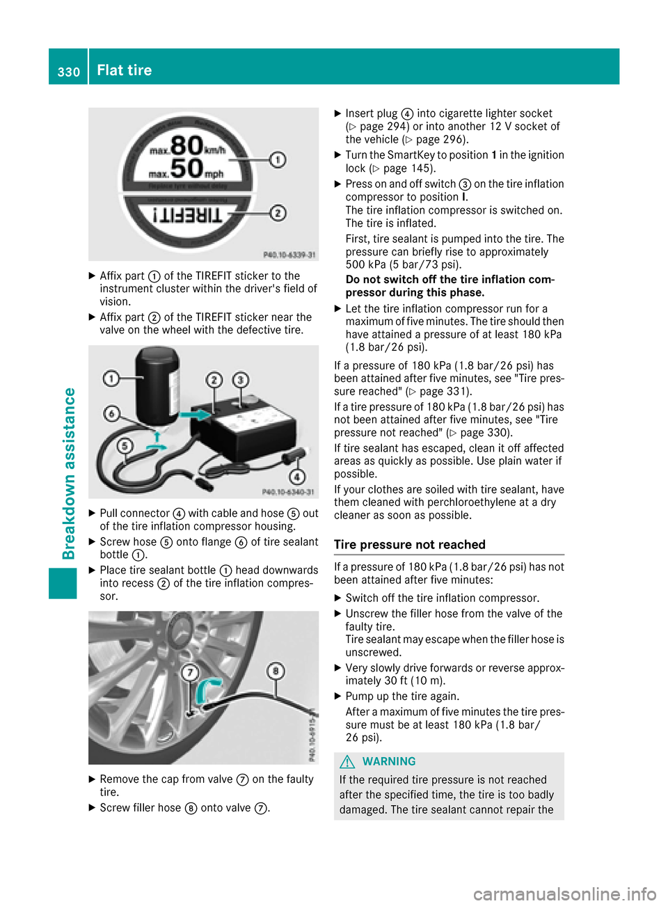
XAffix part:of the TIREFIT sticker to the
instrument cluster within the driver's field of
vision.
XAffix part ;of the TIREFIT sticker near the
valve on the wheel with the defective tire.
XPull connector ?with cable and hose Aout
of the tire inflation compressor housing.
XScrew hose Aonto flange Bof tire sealant
bottle :.
XPlace tire sealant bottle :head downwards
into recess ;of the tire inflation compres-
sor.
XRemove the cap from valve Con the faulty
tire.
XScrew filler hose Donto valve C.
XInsert plug ?into cigarette lighter socket
(Ypage 294) or into another 12 V socket of
the vehicle (Ypage 296).
XTurn the SmartKey to position 1in the ignition
lock (Ypage 145).
XPress on and off switch =on the tire inflation
compressor to position I.
The tire inflation compressor is switched on.
The tire is inflated.
First, tire sealant is pumped into the tire. The
pressure can briefly rise to approximately
500 kPa (5 bar/73 psi).
Do not switch off the tire inflation com-
pressor during this phase.
XLet the tire inflation compressor run for a
maximum of five minutes. The tire should then
have attained a pressure of at least 180 kPa
(1.8 bar/26 psi).
If a pressure of 180 kPa (1.8 bar/26 psi) has
been attained after five minutes, see "Tire pres-
sure reached" (
Ypage 331).
If a tire pressure of 180 kPa (1.8 bar/26 psi) has
not been attained after five minutes, see "Tire
pressure not reached" (
Ypage 330).
If tire sealant has escaped, clean it off affected
areas as quickly as possible. Use plain water if
possible.
If your clothes are soiled with tire sealant, have
them cleaned with pe rchlo
roethylene at a dry
cleaner as soon as possible.
Tire pressure not reached
If a pressure of 180 kPa (1.8 ba r/26 psi) has not
been attained after five minutes:
XSwitch off the tire inflation compressor.
XUnscrew the filler hose from the valve of the
faulty tire.
Tire sealant may escape when the filler hose is
unscrewed.
XVery slowly drive forwards or reverse approx- imately 30 ft (10 m).
XPump upthe tire again.
After a maximum of five minutes the tire pres-
sure must be at least 180 kPa (1.8 bar/
26 psi).
GWARNING
If the required tire pressure is not reached
after the specified time, the tire is too badly
damaged. The tire sealant cannot repair the
330Flat tire
Breakdown assistance
Page 335 of 382
HEnvironmental note
Batteries contain dangerous
substances. It is against the
law to dispose of them with
the household rubbish. They
must be collected separatelyand recycled to protect the
environment.
Dispose of batteries in an
environmentally friendly
manner. Take discharged
batteries to a qualified spe-
cialist workshop or a special
collection point for used bat-
teries.
!Have the battery checked regularly at a
qualified specialist workshop.
Observe the service intervals in the Mainte-
nance Booklet or contact a qualified specialist
workshop for more information.
!Always have work on batteries carried out at
a qualified specialist workshop. Should it, in
exceptional circumstances, be absolutely
necessary to disconnect the 12-volt battery
yourself, observe the following:
Rsecure the vehicle to prevent it from rolling
away.
Rswitch off the ignition.
Ralways disconnect the negative terminal
clamp first, followed by the positive termi-
nal clamp.
After the battery has been disconnected, the
transmission is locked in position P.
After the work has been done, install the bat-
tery and replace the cover of the positive ter-
minal clamp firmly.
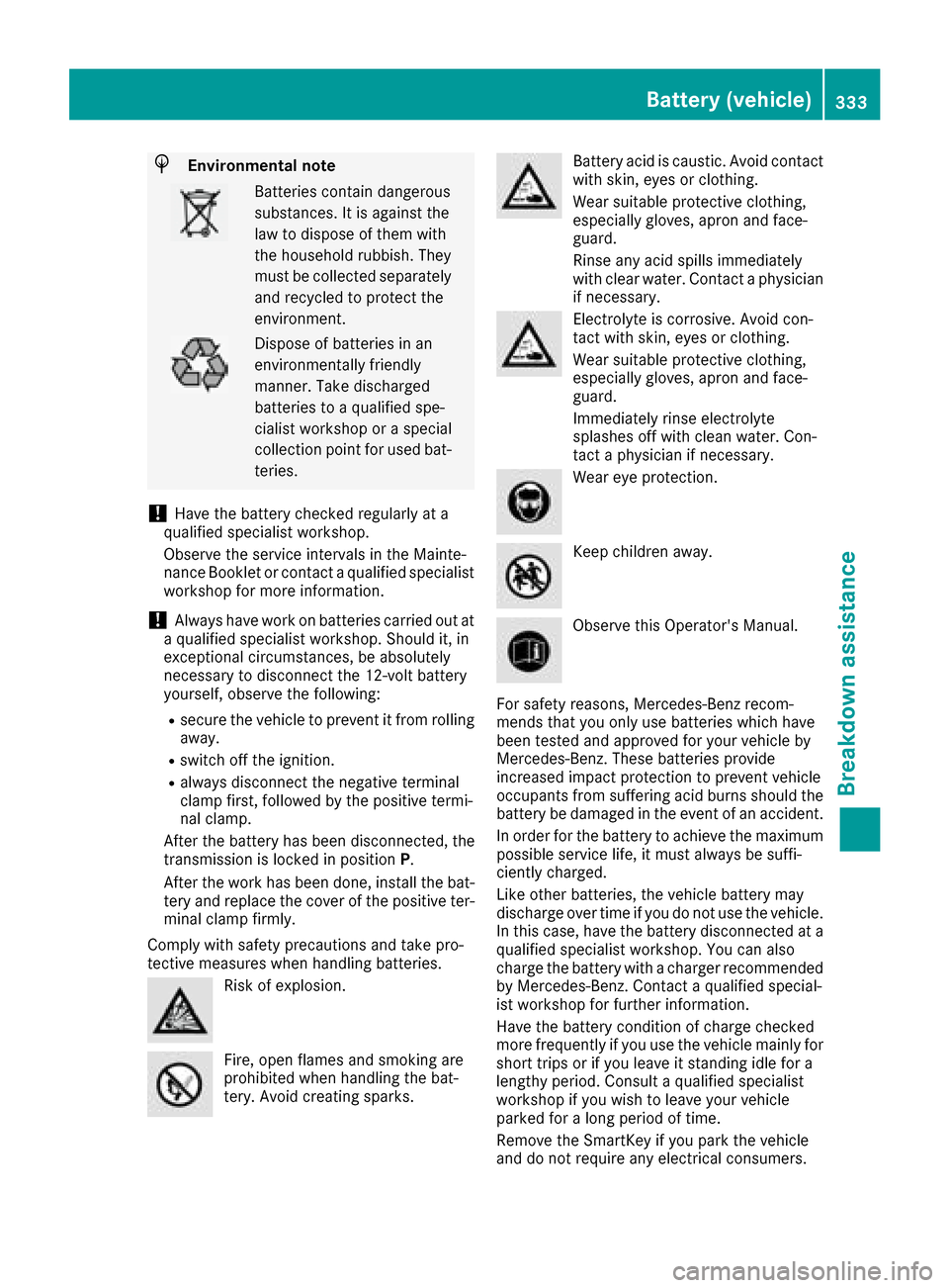
Comply with safety precautions and take pro-
tective measures when handling batteries.
Risk of explosion.
Fire, open flames and smoking are
prohibited when handling the bat-
tery. Avoid creating sparks.
Battery acid is caustic. Avoid contact
with skin, eyes or clothing.
Wear suitable protective clothing,
especially gloves, apron and face-
guard.
Rinse any acid spills immediately
with clear water. Contact a physician
if necessary.
Electrolyte is corrosive. Avoid con-
tact with skin, eyes or clothing.
Wear suitable protective clothing,
especially gloves, apron and face-
guard.
Immediately rinse electrolyte
splashes off with clean water. Con-
tact a physician if necessary.
Wear eye protection.
Keep children away.
Observe this Operator's Manual.
For safety reasons, Mercedes-Benz recom-
mends that you only use batteries which have
been tested and approved for your vehicle by
Mercedes-Benz. These batteries provide
increased impact protection to prevent vehicle
occupants from suffering acid burns should the
battery be damaged in the event of an accident.
In order for the battery to achieve the maximum
possible service life, it must always be suffi-
ciently charged.
Like other batteries, the vehicle battery may
discharge over time if you do not use the vehicle.
In this case, have the battery disconnected at a
qualified specialist workshop. You can also
charge the battery with a charger recommended
by Mercedes-Benz. Contact a qualified special-
ist workshop for further information.
Have the battery condition of charge checked
more frequently if you use the vehicle mainly for
short trips or if you leave it standing idle for a
lengthy period. Consult a qualified specialist
workshop if you wish to leave your vehicle
parked for a long period of time.
Remove the SmartKey if you park the vehicle
and do not require any electrical consumers.
Battery (vehicle)333
Breakdown assistance
Z
Page 338 of 382

RIt is particularly important to observe the described order when connecting and disconnecting
the jumper cables.
RNever connect or disconnect the battery terminals while the engine is running.
GWARNING
A discharged battery can freeze at temperatures below freezing point. When jump-starting the
vehicle or charging the battery, gases can escape from the battery. There is a risk of an explosion. Allow the frozen battery to thaw out before charging it or jump-starting.
If, at low temperatures, the indicator lamps/warning lamps in the instrument cluster do not light up,
it is highly likely that the discharged battery has frozen. In this case, you may neither charge the
battery nor jump-start the vehicle. The service life of a thawed-out battery may be shorter. The
starting characteristics can be impaired, particularly at low temperatures. Have the thawed-out
battery checked at a qualified specialist workshop.
All vehicles:
!Avoid repeated and lengthy starting attempts. Otherwise, the catalytic converter could be
damaged by the non-combusted fuel.
Do not start the vehicle using a rapid charging device. If your vehicle's battery is discharged, the
engine can be jump-started from another vehicle or from a second battery using jumper cables.
Observe the following points:
RThe battery is not accessible in all vehicles. If the other vehicle's battery is not accessible, jump-
start the vehicle using a second battery or a jump-starting device.
RYou may only jump-start the vehicle when the engine and exhaust system are cold.
RAll vehicles except Mercedes-AMG vehicles: do not start the engine if the battery is frozen. Let
the battery thaw first.
RJump-starting may be performed only using batteries with a nominal voltage of 12 V.
ROnly use jumper cables which have a sufficient cross-section and insulated terminal clamps.
RIf the battery is fully discharged, leave the battery that is being used to jump-start connected for
a few minutes before attempting to start. This charges the battery slightly.
RMake sure that the two vehicles do not touch.
Make sure that:
Rthe jumper cables are not damaged.
Rwhen the jumper cables are connected to the battery, uninsulated sections of the terminal clamp
do not come into contact with other metal sections.
Rthe jumper cables cannot come into contact with parts which can move when the engine is
running, such as the V-belt pulley or the fan.
XSecure the vehicle by applying the electric parking brake.
XShift the transmission to position P.
XMake sure that the ignition is switched off. All indicator lamps in the instrument cluster must be
off. When using the SmartKey, turn the SmartKey to position 0in the ignition lock and remove it
(
Ypage 145).
XSwitch off all electrical consumers, e.g. rear window defroster, lighting, etc.
XOpen the hood.
336Jump-starting
Breakdown assistance
Page 341 of 382
The battery must be connected and charged.
Otherwise, you:
Rcannot turn the SmartKey to position2in the
ignition lock
Rcannot release the electric parking brake
Rcannot shift the automatic transmission to
position N
Disarm the automatic locking feature before the vehicle is towed (
Ypage 84). You could other-
wise be locked out when pushing or towing the
vehicle.
If the vehicle is in a dangerous area, it can be
towed out of that area with both axles on the
ground. In this case, the towing distance must
not be greater than 165 ft (50 m)and must not
exceed a towing speed of 6 mph (10 km/h). For
longer distances, have the vehicle loaded and
transported.
Installing/removing the towing eye
Installing the towing eye
GWARNING
The exhaust tail pipe may be very hot. There is
a risk of burns when removing the rear cover.
Do not touch the exhaust pipe. Take particular
care when removing the rear cover.
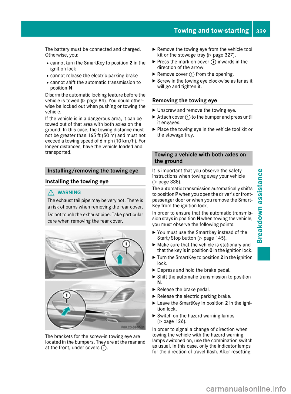
The brackets for the screw-in towing eye are
located in the bumpers. They are at the rear and
at the front, under covers :.
XRemove the towing eye from the vehicle tool
kit or the stowage tray (Ypage 327).
XPress the mark on cover:inwards in the
direction of the arrow.
XRemove cover :from the opening.
XScrew in the towing eye clockwise as far as it
will go and tighten it.
Removing the towing eye
XUnscrew and remove the towing eye.
XAttach cover :to the bumper and press until
it engages.
XPlace the towing eye in the vehicle tool kit or
the stowage tray.
Towing a vehicle with both axles on
the ground
It is important that you observe the safety
instructions when towing away your vehicle
(
Ypage 338).
The automatic transmission automatically shifts
to position Pwhen you open the driver's or front-
passenger door or when you remove the Smart-
Key from the ignition lock.
In order to ensure that the automatic transmis-
sion stays in position Nwhen towing the vehicle,
you must observe the following points:
XYou must use the SmartKey instead of the
Start/Stop button (Ypage 145).
XMake sure that the vehicle is stationary and
that the key is in position 0in the ignition lock.
XTurn the SmartKey to position 2in the ignition
lock.
XDepress and hold the brake pedal.
XShift the automatic transmission to position
N .
XRelease the brake pedal.
XRelease the electric parking brake.
XLeave the SmartKey in position 2in the igni-
tion lock.
XSwitch on the hazard warning lamps
(Ypage 126).
In order to signal a change of direction when
towing the vehicle with the hazard warning
lamps switched on, use the combination switch
as usual. In this case, only the indicator lamps
for the direction of travel flash. After resetting
Towing and tow-starting339
Breakdown assistance
Z
Page 342 of 382
the combination switch, the hazard warning
lamp starts flashing again.
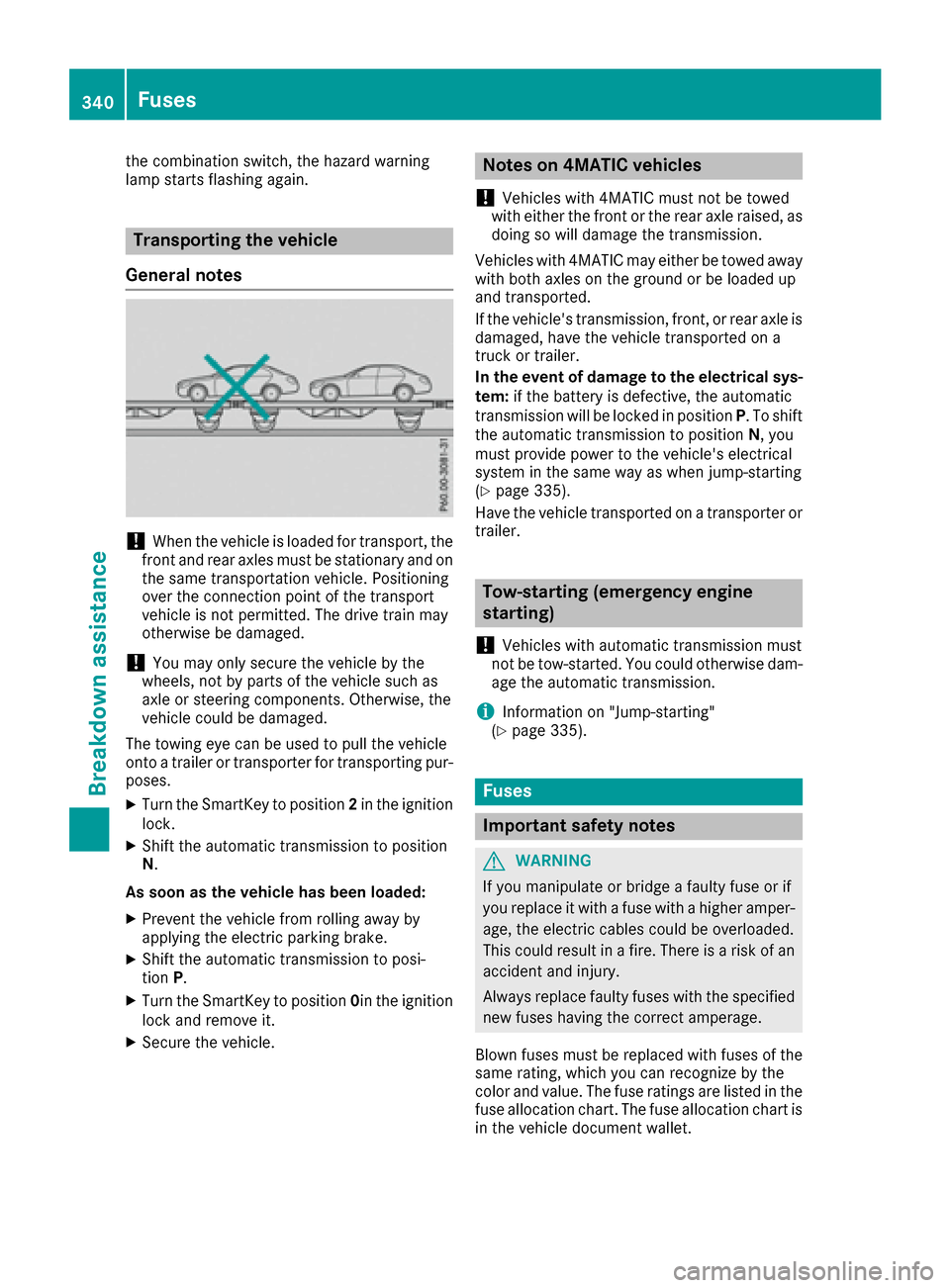
Transporting the vehicle
General notes
!When the vehicle is loaded for transport, the
front and rear axles must be stationary and on
the same transportation vehicle. Positioning
over the connection point of the transport
vehicle is not permitted. The drive train may
otherwise be damaged.
!You may only secure the vehicle by the
wheels, not by parts of the vehicle such as
axle or steering components. Otherwise, the
vehicle could be damaged.
The towing eye can be used to pull the vehicle
onto a trailer or transporter for transporting pur-
poses.
XTurn the SmartKey to position 2in the ignition
lock.
XShift the automatic transmission to position
N.
As soon as the vehicle has been loaded:
XPrevent the vehicle from rolling away by
applying the electric parking brake.
XShift the automatic transmission to posi-
tion P.
XTurn the SmartKey to position 0in the ignition
lock and remove it.
XSecure the vehicle.
Notes on 4MATIC vehicles
!
Vehicles with 4MATIC must not be towed
with either the front or the rear axle raised, as
doing so will damage the transmission.
Vehicles with 4MATIC may either be towed away with both axles on the ground or be loaded up
and transported.
If the vehicle's transmission, front, or rear axle is
damaged, have the vehicle transported on a
truck or trailer.
In the event of damage to the electrical sys-
tem: if the battery is defective, the automatic
transmission will be locked in position P. To shift
the automatic transmission to position N, you
must provide power to the vehicle's electrical
system in the same way as when jump-starting
(
Ypage 335).
Have the vehicle transported on a transporter or
trailer.
Tow-starting (emergency engine
starting)
!
Vehicles with automatic transmission must
not be tow-started. You could otherwise dam-
age the automatic transmission.
iInformation on "Jump-starting"
(Ypage 335).
Fuses
Important safety notes
GWARNING
If you manipulate or bridge a faulty fuse or if
you replace it with a fuse with a higher amper- age, the electric cables could be overloaded.
This could result in a fire. There is a risk of an
accident and injury.
Always replace faulty fuses with the specified
new fuses having the correct amperage.
Blown fuses must be replaced with fuses of the
same rating, which you can recognize by the
color and value. The fuse ratings are listed in the
fuse allocation chart. The fuse allocation chart is
in the vehicle document wallet.
340Fuses
Breakdown assistance
Page 343 of 382
The fuses in your vehicle serve to close down
faulty circuits. If a fuse blows, all the compo-
nents on the circuit and their functions stop
operating.
If a newly inserted fuse also blows, have the
cause traced and rectified at a qualified special-
ist workshop, e.g. an authorized Mercedes-Benz
Center.
!Only use fuses that have been approved for
Mercedes-Benz vehicles and which have the
correct fuse rating for the system concerned.
Otherwise, components or systems could be
damaged.
!Make sure that no moisture can enter the
fuse box when the cover is open.
!When closing the cover, make sure that it is
lying correctly on the fuse box. Moisture seep-
ing in or dirt could otherwise impair the oper-
ation of the fuses.
Before changing a fuse
Observe the important safety notes
(Ypage 340)
XSwitch off the engine.
XSwitch off all electrical consumers.
XMake sure that the ignition is switched off
(Ypage 145).
or
XWhen using the SmartKey, turn the SmartKey
to position 0in the ignition lock and remove it
(
Ypage 145).
XSecure the vehicle against rolling away
(Ypage 162).
All indicator lamps in the instrument cluster
must be off.
The fuses are located in various fuse boxes:
RFuse box on the driver's side of the dashboard
RFuse box in the front-passenger footwell
RFuse box in the engine compartment on the
left-hand side of the vehicle, when viewed in
the direction of travel
RFuse box in the trunk
Dashboard fuse box
The fuse box is under a cover on the side of the dashboard. You can obtain further information
from an authorized Mercedes-Benz Center.
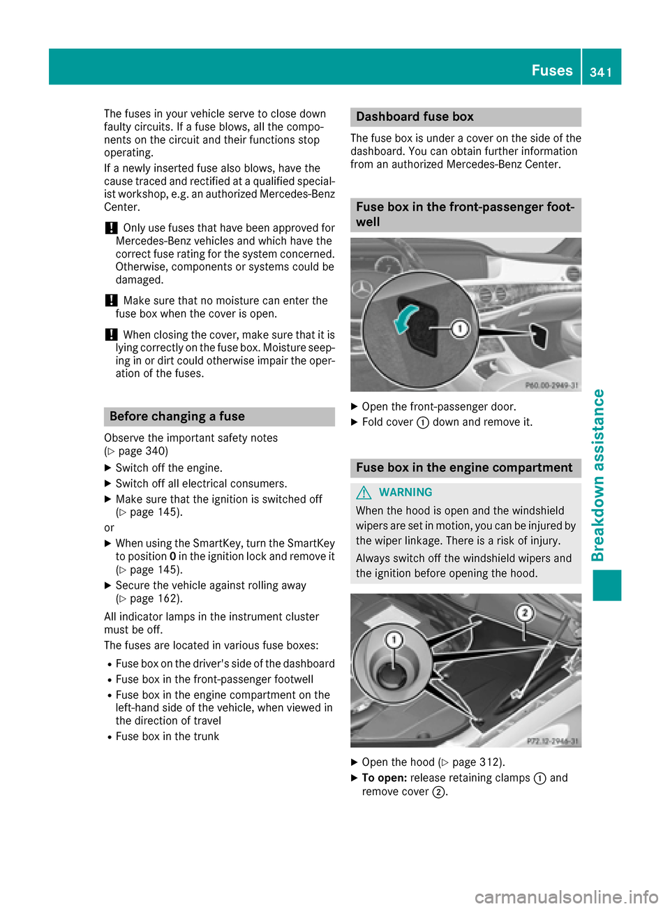
Fuse box in the front-passenger foot-
well
XOpen the front-passenger door.
XFold cover :down and remove it.
Fuse box in the engine compartment
GWARNING
When the hood is open and the windshield
wipers are set in motion, you can be injured by
the wiper linkage. There is a risk of injury.
Always switch off the windshield wipers and
the ignition before opening the hood.
XOpen the hood (Ypage 312).
XTo open: release retaining clamps :and
remove cover ;.
Fuses341
Breakdown assistance
Z
Page 352 of 382
trigger illumination of the TPMS low tire pres-sure telltale.
Your vehicle has also been equipped with a
TPMS malfunction indicator to indicate when
the system is not operating properly. The
TPMS malfunction indicator is combined with
the low tire pressure telltale. When the sys-
tem detects a malfunction, the warning lamp
will flash for approximately a minute and thenremain continuously illuminated. This
sequence will be repeated every time the vehi-
cle is started as long as the malfunction
exists. When the malfunction indicator is illu-
minated, the system may not be able to detect
or signal low tire pressure as intended.
TPMS malfunctions may occur for a variety of
reasons, including the installation of incom-
patible replacement or alternate tires or
wheels on the vehicle that prevent the TPMS
from functioning properly. Always check the
TPMS malfunction telltale after replacing one
or more tires or wheels on your vehicle to
ensure that the replacement or alternate Tires
and wheels allow the TPMS to continue to
function properly.
It is the driver's responsibility to set the tire
pressure to that recommended for cold tires
which is suita ble fo
r the operating situation
(Ypage 346). Note that the correct tire pressure
for the current operating situation must first be
taught-in to the tire pressure monitor. If a sub-
stantial loss of pressure occurs, the warning
threshold for the warning message is aligned to
the taught-in reference values. Restart the tire
pressure monitor after adjusting the pressure of
the cold tires (
Ypage 351). The current pres-
sures are saved as new reference values. As a
result, a warning message will appear if the tire pressure drops significantly.
The tire pressure monitor does not warn you of
an incorrectly set tire pressure. Observe the
notes on the recommended tire pressure
(
Ypage 346).
The tire pressure monitor is not able to warn you
of a sudden loss of pressure, e.g. if the tire is
penetrated by a foreign object. In the event of a
sudden loss of pressure, bring the vehicle to a
halt by braking carefully. Avoid abrupt steering
movements. The tire pressure monitor has a yellow warning
lamp in the instrument cluster for indicating
pressure loss or a malfunction. Whether the
warning lamp flashes or lights up indicates
whether a tire pressure is too low or the tire
pressure monitor is malfunctioning:
Rif the warning lamp is lit continuously, the tire
pressure on one or more tires is significantly
too low. The tire pressure monitor is not mal-
functioning.
Rif the warning lamp flashes for around a
minute and then remains lit constantly, the
tire pressure monitor is malfunctioning.
In addition to the warning lamp, a message
appears in the multifunction display. Observe
the information on display messages
(
Ypage 252).
It may take up to ten minutes for a malfunction
of the tire pressure monitor to be indicated. A
malfunction will be indicated by the tire pres-
sure warning lamp flashing for approximately
one minute and then remaining lit. When the
malfunction has been rectified, the tire pressure
warning lamp goes out after a few minutes of
driving.
The tire pressure values indicated by the on-
board computer may differ from those meas-
ured at a gas station with a pressure gauge. The
tire pressures shown by the on-board computer
refer to those measured at sea level. At high
altitudes, the tire pressure values indicated by a pressure gauge are higher than those shown by
the on-board computer. In this case, do not
reduce the tire pressures .
T
he operation of the tire pressure monitor can
be affected by interference from radio transmit-
ting equipment (e.g. radio headphones, two-way
radios) that may be being operated in or near the
vehicle.
Checking the tire pressure electroni-
cally
XMake sure that the SmartKey is in position 2
in the ignition lock (Ypage 145).
XUse ò on the steering wheel to call up the
list of menus.
XPress 9or: on the steering wheel to
select the Servicemenu.
XPress theabutton.
350Tire pressure
Wheels and tires