2017 MERCEDES-BENZ S-Class CABRIOLET tow
[x] Cancel search: towPage 23 of 338

Optional equipment weight (defi-
nition) ............................................ 320
PSI (pounds per square inch) (def-
inition) ...........................................319
Replacing ....................................... 320
Service life ..................................... 303
Sidewall (definition) ....................... 320
Snow chains .................................. 304
Speed rating (definition) ................ 319
Storing ...........................................3 21
Structure and characteristics
(definition) ..................................... 318
Summer tires in winter .................. 304
Temperature .................................. 315
TIN (Tire Identification Number)
(definition) ..................................... 320
Tire bead (definition) ......................3 20
Tire pressure (definition) ................ 320
Tire pressures (recommended) ...... 319
Tire size (data) ............................... 325
Tire size designation, load-bearing
capacity, speed rating .................... 315
Tire tread ....................................... 303
Tire tread (definition) ..................... 320
Total load limit (definition) ............. 320
Traction ......................................... 314
Traction (definition) ....................... 320
Tread wear ..................................... 314
Uniform Tire Quality Grading
Standards ...................................... 314
Uniform Tire Quality Grading
Standards (definition) .................... 318
Wear indicator (definition) ............. 320
Wheel and tire combination ........... 325
Wheel rim (definition) .................... 319
see Flat tire
Touchpad
Changing the station/music
track .............................................. 246
Character suggestions ................... 245
Deleting characters ....................... 246
Entering a space ............................ 246
Entering characters ....................... 245
Gesture control .............................. 245
Handwriting recognition ................ 246
Operating the touchpad ................. 245
Overview ........................................ 245
Qu
ick access for Audio .................. 246 Quick access for telephone ........... 246
Switching ....................................... 245
Switching input line ....................... 246
Tow-starting
Emergency engine starting ............ 299
Important safety notes .................. 297
Towing away
Important safety guidelines ........... 297
Installing the towing eye ................ 298
Notes for 4MATIC vehicles ............ 299
Removing the towing eye ............... 298
Transporting the vehicle ................ 299
With both axles on the ground ....... 298
Towing eye ......................................... 288
Traffic reports
see also Digital Operator's Man-
ual .................................................. 243
Traffic Sign Assist
Activating ....................................... 177
Display message ............................ 223
Function/notes ............................. 177
Important safety notes .................. 177
Instrument cluster display ............. 178
Switching on/off ........................... 199
Transfer case ..................................... 138
Transmission
see Automatic transmission
Transporting the vehicle .................. 299
Trim pieces (cleaning instruc-
tions) .................................................. 286
Trip computer (on-board com-
puter) .................................................. 192
Trip odometer
Calling up ....................................... 191
Resetting (on-board computer) ...... 192
Trunk
Emergency release .......................... 84
Emergency release button ............... 85
Important safety notes .................... 80
Locking separately ........................... 84
Opening ........................................... 81
Opening/closing (automatically
from inside) ...................................... 83
Opening/closing (automatically
from outside) ................................... 81
Opening/closing (from outside,
HANDS-FREE ACCESS) .................... 82
Index21
Page 24 of 338

Power closing ..................................79
Trunk lid
Display message ............................ 229
Obstacle recognition ........................8 0
Opening dimensions ......................3 34
Opening/closing .............................. 80
Trunk load (maximum) ......................334
Trunk partition
Display message ............................ 230
General notes .................................. 91
Opening/closing .............................. 91
Turn signals
Display message ............................ 216
Switching on/off ........................... 108
Two-way radio
Frequencies ................................... 327
Installation ..................................... 327
Transmission output (maximum) .... 327
Windshield (infrared reflective) ...... 271
Type identification plate
see Vehicle identification plate
U
UnlockingEmergency unlocking ....................... 79
From inside the vehicle (central
unlocking button) .............................7 8
Upshift indicator (on-board com-
puter, Mercedes-AMG vehicles) .......203
USB devices
Connecting to the Media Inter-
face ............................................... 252
V
Vanity mirror (in the sun visor) ........259
Vehicle
Correct use ...................................... 29
Data acquisition ............................... 30
Display message ............................ 227
Equipment ....................................... 26
Individual settings .......................... 198
Limited Warranty .............................3 0
Loading .......................................... 311
Locking (in an emergency) ............... 79
Locking (SmartKey) .......................... 72
Lowering ........................................ 325 Maintenance .................................... 27
Operating safety .............................. 28
Parking .......................................... 140
Parking for a long period ................ 143
Pulling away ................................... 127
Raising ........................................... 322
Reporting problems ......................... 29
Securing from rolling away ............ 321
Towing away .................................. 297
Transporting .................................. 299
Unlocking (in an emergency) ........... 79
Unlocking (SmartKey) ...................... 72
Vehicle data ................................... 334
Vehicle dimensions ........................... 334
Vehicle emergency locking ................ 79
Vehicle identification number
see VIN
Vehicle identification plate .............. 328
Vehicle level
AIRMATIC ...................................... 160
Display message ............................ 220
Vehicle tool kit .................................. 288
Video
Operating the DVD ......................... 196
see also Digital Operator's Man-
ual .................................................. 243
Video-AUX
Connecting an external video
source ............................................ 253
VIN
Type plate ...................................... 328
W
Warning and indicator lampsABS ................................................ 235
Brakes ........................................... 234
Check Engine ................................. 238
Coolant .......................................... 238
Distance warning ........................... 240
ESP
®.............................................. 235
ESP®OFF ....................................... 237
Fuel tank ........................................ 238
General notes ................................ 232
Overview .......................................... 34
Parking brake ................................ 237
PASSENGER AIR BAG ...................... 42
Reserve fuel ................................... 238
22Index
Page 31 of 338

Diagnostics connection
The diagnosticsconnection is only intended fo r
th econnection of diagnostic equipmen tat a
qualified specialis tworkshop .
GWARNING
If you connec tequipmen tto adiagnostic s
connection in th evehicle, it may affec tth e
operation of vehicle systems .As aresult ,th e
operatin gsafet yof th evehicle could be affec -
ted. There is aris kof an accident.
Only connec tequipmen tto adiagnostic scon-
nection in th evehicle, whic his approved fo r
your vehicle by Mercedes-Benz.
GWARNING
Objects in th edriver's footwell can restric tth e
peda ltrave lor obstruct adepressed pedal.
The operatin gand road safet yof th evehicle is
jeopardized. There is aris kof an accident.
Mak esur ethat all objects in th evehicle are
stowed correctly, and that they canno tente r
th edriver's footwell. Install th efloormat s
securely and as specifie din order to ensur e
sufficien tclearanc efo rth epedals. Do no tuse
loose floormat sand do no tplac efloormat son
to pof on eanother.
!If th eengin eis switched of fand equipmen t
on th ediagnostic sconnection is used ,th e
starter battery may discharge.
Connectin gequipmen tto th ediagnostic scon-
nection can lead to emission smonitorin ginfor-
mation bein greset ,fo rexample. Thi smay lead
to th evehicle failin gto mee tth erequirements of
th enext emission stest durin gth emain inspec-
tion .
Qualified specialist workshop
An authorized Mercedes-Ben zCente ris aquali-
fie dspecialis tworkshop .It has th enecessary
specialis tknowledge ,tools and qualification sto
correctl ycarry out th ewor krequire don your
vehicle. Thi sis especially th ecas efo rwor krel -
evant to safety.
Observ eth enote sin th eMaintenance Booklet .Always hav
eth efollowin gwor kcarrie dout at an
authorized Mercedes-Ben zCenter:
Rwor krelevant to safet y
Rserviceand maintenance wor k
Rrepair work
Ralterations, installation wor kand modifica-
tion s
Rworkon electronic component s
Correct use
If you remov eany warnin gstickers ,you or oth-
ers could fail to recogniz ecertain dangers.
Leave warnin gstickers in position .
Observ eth efollowin ginformation when drivin g
your vehicle:
Rth esafet ynote sin this manual
Rtechnical dat afo rth evehicle
Rtraffic rule sand regulation s
Rlaws and safetystandard spertainin gto moto r
vehicles
Problem swit hyou rvehicle
If you should experience aproblem wit hyour
vehicle, particularly on ethat you believe may
affec tit s saf eoperation ,we urg eyou to contact
an authorized Mercedes-Ben zCente rimmedi-
ately to hav eth eproblem diagnosed and recti -
fied. If th eproblem is no tresolved to your sat -
isfaction ,please discus sth eproblem again wit h
an authorized Mercedes-Ben zCente ror ,if nec-
essary, contact us at on eof th efollowin g
addresses.
In th eUSA
Customer Assistanc eCente r
Mercedes-Ben zUSA, LL C
3 Mercedes Drive
Montvale, NJ 07645-0350
In Canad a
Customer Relation sDepartmen t
Mercedes-Ben zCanada, Inc.
98 Vanderhoo fAvenue
Toronto ,Ontario M4 G4C9
Reporting safet ydefect s
USAonly:
Operating safety29
Introduction
Z
Page 42 of 338

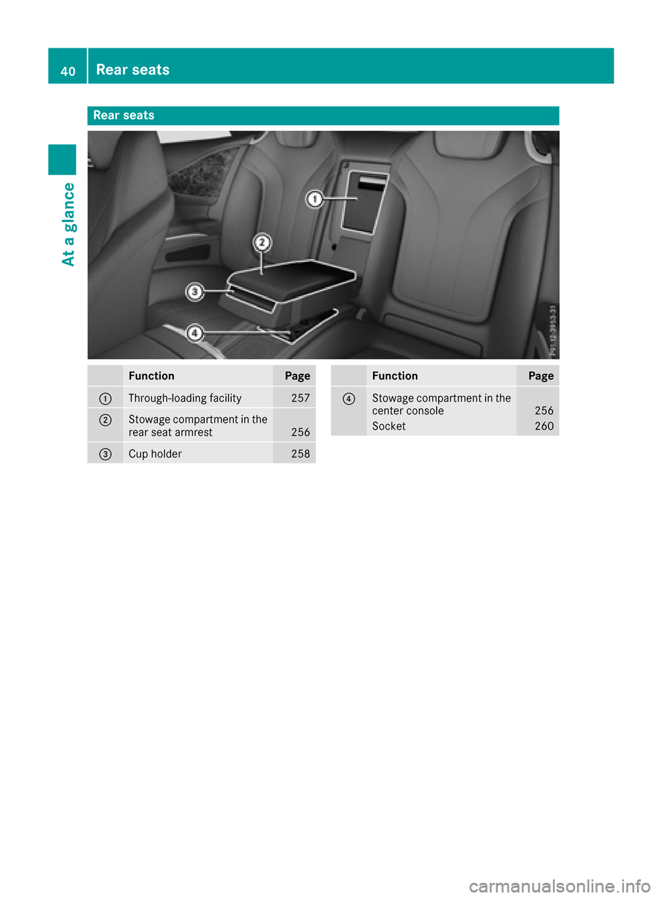
Rear seats
FunctionPage
:Through-loading facility257
;Stowage compartment in the
rear seat armrest256
=Cup holder258
FunctionPage
?Stowage compartment in the
center console256
Socket260
40Rear seats
At a glance
Page 56 of 338

GWARNING
If you place objects or clothing on the roll bar
covers, these could impair roll bar extension.
The roll bars may then not protect the vehicle occupants as intended. In addition, objects
could endanger the vehicle occupants when
the roll bar is extending. This poses an
increased risk of injury or even fatal injury.
Ensure that the movement area of the roll bar
covers is kept clear. Always stow all objects in
the vehicle correctly.
The roll bars are under the covers behind the
rear head restraints. They extend if systems
detect that the vehicle is in danger of rollover.
Once the roll bars are extended, an open soft top
can no longer be closed. In this case, visit the
nearest qualified specialist workshop.
Deployment of Emergency Tensioning
Devices and air bags
Important safety notes
GWARNING
The air bag parts are hot after an air bag has
been deployed. There is a risk of injury.
Do not touch the air bag parts. Have a
deployed air bag replaced at a qualified spe-
cialist workshop as soon as possible.
GWARNING
A deployed air bag no longer offers any pro-
tection and cannot provide the intended pro-
tection in an accident. There is an increased
risk of injury.
Have the vehicle towed to a qualified special-
ist workshop in order to have a deployed air
bag replaced.
It is important for your safety and that of your
passenger to have deployed air bags replaced
and to have any malfunctioning air bags
repaired. This will help to make sure the air bags
continue to perform their protective function for
the vehicle occupants in the event of a crash.
GWARNING
Emergency Tensioning Devices that have
deployed pyrotechnically are no longer opera-
tional and are unable to perform their inten-
ded protective function. This poses an
increased risk of injury or even fatal injury.
Have pyrotechnically triggered Emergency
Tensioning Devices replaced immediately at a
qualified specialist workshop.
An electric motor is used by PRE-SAFE
®to trig-
ger the tightening of the seat belt in hazardous
situations. This procedure is reversible.
If Emergency Tensioning Devices are triggered
or air bags are deployed, you will hear a bang,
and a small amount of powder may also be
released. The 6restraint system warning
lamp lights up.
Only in rare cases will the bang affect your hear-
ing. The powder that is released generally does
not constitute a health hazard, but it may cause short-term breathing difficulties in people with
asthma or other respiratory problems. Provided
it is safe to do so, you should leave the vehicle
immediately or open the window in order to pre-
vent breathing difficulties.
Air bags and pyrotechnic Emergency Tensioning
Devices (ETDs) contain perchlorate material,
which may require special handling and regard
for the environment. National guidelines must
be observed during disposal. In California, see
www.dtsc.ca.gov/HazardousWaste/
Perchlorate/index.cfm.
54Occupant safety
Safety
Page 61 of 338

You can obtain further information about the
correct child restraint system from any author-
ized Mercedes-Benz Center.
GWARNING
If the child restraint system is installed incor-
rectly on a suitable seat, it cannot protect as
intended. The child cannot then be restrained
in the event of an accident, heavy braking or
sudden changes of direction. There is an
increased risk of injury, possibly even fatal.
Make sure that you observe the child restraint
system manufacturer's installation instruc-
tions and the notes on use. Please ensure,
that the base of the child restraint system is
always resting completely on the seat cush-
ion. Never place objects, e.g. cushions, under or behind the child restraint system. Only use
child restraint systems with the original cover
designed for them. Only replace damaged
covers with genuine covers.
GWARNING
If the child restraint system is installed incor-
rectly or is not secured, it can come loose in
the event of an accident, heavy braking or a
sudden change in direction. The child
restraint system could be thrown about, strik-
ing vehicle occupants. There is an increased
risk of injury, possibly even fatal.
Always install child restraint systems prop-
erly, even if they are not being used. Make
sure that you observe the child restraint sys-
tem manufacturer's installation instructions.
You will find further information on stowing
objects, luggage or loads under "Loading guide-
lines" (
Ypage 254).
GWARNING
Child restraint systems or their securing sys-
tems which have been damaged or subjected
to a load in an accident can no longer protect
as intended. The child cannot then be
restrained in the event of an accident, heavy
braking or sudden changes of direction. There is an increased risk of injury, possibly even
fatal.
Replace child restraint systems which have
been damaged or subjected to a load in an
accident as soon as possible. Have the secur-
ing systems on the child restraint system
checked at a qualified specialist workshop,
before you install a child restraint system
again.
The securing systems of child restraint systems
are:
Rthe seat belt system
Rthe LATCH-type (ISOFIX) securing rings
If it is absolutely necessary to carry a child on
the front-passenger seat, be sure to observe the
information on the "Occupant Classification
System (OCS)" (
Ypage 49). There you will also
find information on deactivating the front-
passenger front air bag.
All child restraint systems must meet the fol-
lowing standards:
RU.S. Federal Motor Vehicle Safety Standards
213 and 225
RCanadian Motor Vehicle Safety Standards
213 and 210.2
Confirmation that the child restraint system cor-
responds to the standards can be found on an
instruction label on the child restraint system.
This confirmation can also be found in the instal-
lation instructions that are included with the
child restraint system.
Observe the warning labels in the vehicle inte-
rior and on the child restraint system.
LATCH-type (ISOFIX) child seat secur-
ing system
GWARNING
LATCH-type (ISOFIX) child restraint systems
do not offer sufficient protective effect for
children whose weight is greater than 48 lbs
(22 kg) who are secured using the safety belt integrated in the child restraint system. In the
event of an accident, a child might not be
restrained correctly. This poses an increased
risk of injury or even fatal injury.
If the child weighs more than 48 lbs (22 kg),
only use LATCH-type (ISOFIX) child restraint
systems with which the child is also secured
Children in the vehicle59
Safety
Z
Page 81 of 338

If a locked door is opened from the inside, the
previous unlock status of the vehicle will be
taken into consideration if:
Rthe vehicle was locked using the locking but-
ton for the central locking, or
Rif the vehicle was locked automatically
The vehicle will be fully unlocked if it had previ-
ously been fully unlocked. If only the driver's
door had been previously unlocked, only the
door which has been opened from the inside is
unlocked.
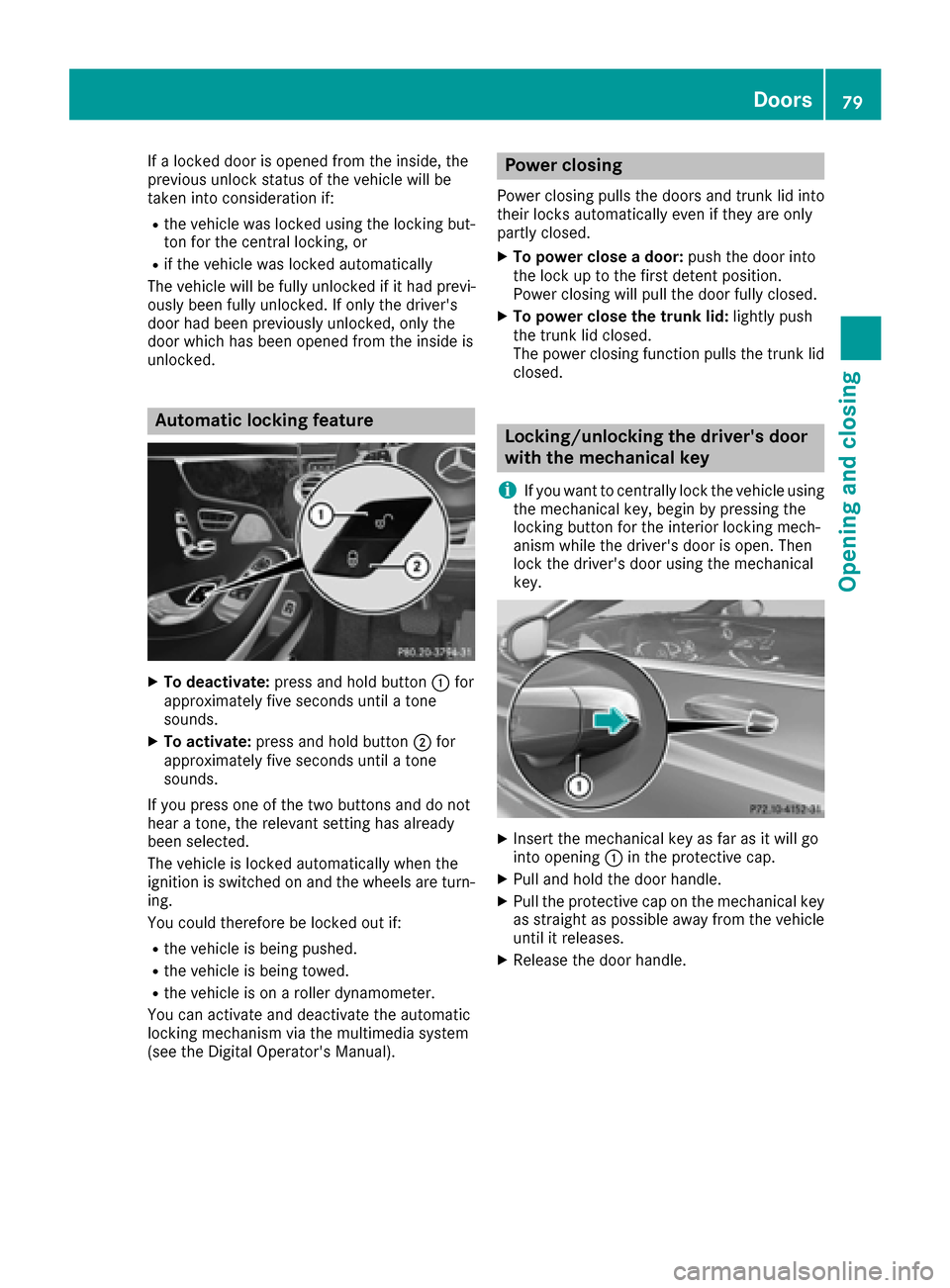
Automatic locking feature
XTo deactivate: press and hold button :for
approximately five seconds until a tone
sounds.
XTo activate: press and hold button ;for
approximately five seconds until a tone
sounds.
If you press one of the two buttons and do not
hear a tone, the relevant setting has already
been selected.
The vehicle is locked automatically when the
ignition is switched on and the wheels are turn-
ing.
You could therefore be locked out if:
Rthe vehicle is being pushed.
Rthe vehicle is being towed.
Rthe vehicle is on a roller dynamometer.
You can activate and deactivate the automatic
locking mechanism via the multimedia system
(see the Digital Operator's Manual).
Power closing
Power closing pulls the doors and trunk lid into
their locks automatically even if they are only
partly closed.
XTo power close a door: push the door into
the lock up to the first detent position.
Power closing will pull the door fully closed.
XTo power close the trunk lid: lightly push
the trunk lid closed.
The power closing function pulls the trunk lid
closed.
Locking/unlocking the driver's door
with the mechanical key
i
If you want to centrally lock the vehicle using
the mechanical key, begin by pressing the
locking button for the interior locking mech-
anism while the driver's door is open. Then
lock the driver's door using the mechanical
key.
XInsert the mechanical key as far as it will go
into opening :in the protective cap.
XPull and hold the door handle.
XPull the protective cap on the mechanical key
as straight as possible away from the vehicle
until it releases.
XRelease the door handle.
Doors79
Opening and closing
Z
Page 88 of 338

GWARNING
The reversing feature does not react:
Rto soft, light and thin objects, e.g. small fin-
gers
Rwhile resetting
This means that the reversing feature cannot
prevent someone being trapped in these sit-
uations. There is a risk of injury.
Make sure that no body parts are in close
proximity during the closing procedure. If
someone becomes trapped, press the switch
to open the side window again.
Opening and closing the side win-
dows
The switches for all side windows are located on the driver's door. There is also a switch for the
front-passenger side window on the front-
passenger door.
The switches on the driver's door take prece-
dence.
:Front left
;Front right
=Rear right
?Rear left
XTurn the SmartKey to position 1or 2in the
ignition lock.
XTo open manually: press and hold the cor-
responding button.
XTo open fully: press the switch beyond the
point of resistance and release it.
Automatic operation is started.
XTo close manually: pull and hold the corre-
sponding button.
XTo fully close the front side windows: pull
the button beyond the point of resistance and
release it.
Automatic operation is started.
XTo interrupt automatic operation: press/
pull the corresponding switch again.
You can continue to operate the side windows
after you switch off the engine or remove the
SmartKey. This function remains active for five
minutes or until you open a door.
Before opening or closing the side windows, a
check is carried out to see whether a valid
SmartKey is in the vehicle. The check is carried out if you use the start/stop button instead of a
SmartKey in the ignition and you press or pull a
button while the engine is switched off. This is
carried out by means of a brief radio connection
between the vehicle and the SmartKey.
Opening and closing all side windows
Using the switch on the center console
GWARNING
While closing the side windows, body parts in
the closing area could become trapped. There is a risk of injury.
When closing make sure that no parts of the
body are in the closing area. If somebody
becomes trapped, release the switch or press
the switch to open the side window again.
Use switch :in the stowage compartment
under the armrest to close or open all side win-
dows simultaneously.
86Side windows
Opening and closing