2017 MERCEDES-BENZ GLE43AMG SUV trunk
[x] Cancel search: trunkPage 24 of 366

Trip computer (on-board com-
puter).................................................. 209
Trip odometer
Calling up ....................................... 209
Resetting (on-board computer) ...... 210
Trunk
see Tailgate
Trunk load (maximum) ...................... 358
Turn signals
Display message ............................ 233
Switching on/off ........................... 105
Two-way radio
Frequencies ................................... 350
Installation ..................................... 350
Transmission output (maximum) .... 350
TWR (Tongue Weight Rating) (defi-
nition) ................................................. 340
Type identification plate
see Vehicle identification plate
U
UnlockingEmergency unlocking ....................... 78
From inside the vehicle (central
unlocking button) ............................. 77
Upshift indicator (on-board com-
puter, Mercedes-AMG vehicles) ....... 218
USB devices
Connecting to the Media Inter-
face ...............................................2 68
V
Vanity mirror (in the sun visor)........279
Vehicle
Correct use ...................................... 28
Data acquisition ............................... 29
Display message ............................ 246
Equipment ....................................... 25
Individual settings .......................... 215
Limited Warranty .............................2 9
Loading .......................................... 331
Locking (in an emergency) ............... 78
Locking (SmartKey) .......................... 71
Lowering ........................................ 345
Maintenance .................................... 26
Operating safety .............................. 27 Parking .......................................... 145
Parking for a long period ................ 148
Pulling away ................................... 128
Raising ........................................... 342
Reporting problems ......................... 28
Securing from rolling away ............ 342
Towing away .................................. 316
Transporting .................................. 318
Unlocking (in an emergency) ........... 78
Unlocking (SmartKey) ...................... 71
Vehicle data ................................... 358
Vehicle data
Roof load (maximum) ..................... 358
Trunk load (maximum) ................... 358
Vehicle data (off-road driving)
Approach/departure angle ............ 360
Fording depth ................................ 359
Maximum gradient climbing abil-
ity .................................................. 360
Vehicle dimensions ........................... 358
Vehicle emergency locking ................ 78
Vehicle identification number
see VIN
Vehicle identification plate .............. 351
Vehicle level
AIRMATIC ...................................... 171
Vehicle level (display message) ....... 238
Vehicle tool kit .................................. 306
Video
Operating the DVD ......................... 212
see also Digital Operator's Man-
ual .................................................. 263
VIN ...................................................... 351
Seat ............................................... 352
Type pla
te ...................................... 351
W
Warning and indicator lamps
ABS ................................................ 253
Brakes ........................................... 252
Check Engine ................................. 259
Coolant .......................................... 259
Distance Pilot DISTRONIC ............. 261
Distance warning ........................... 261
ESP
®.............................................. 255
ESP®OFF ....................................... 256
Fuel tank ........................................ 259
22Index
Page 149 of 366
Applyingorreleasing manually
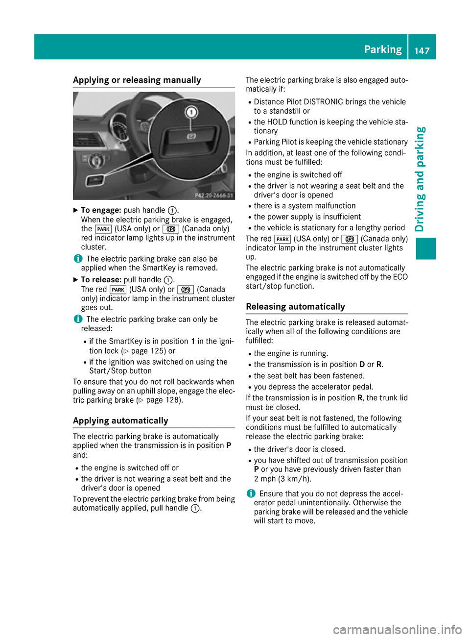
XTo engage: push handle :.
When th eelectric parking brak eis engaged,
th eF (USAonly) or !(Canada only)
red indicator lamp lights up in th einstrumen t
cluster.
iThe electric parking brak ecan also be
applie dwhen th eSmartKey is removed.
XTo release: pull handle:.
The red F(USAonly) or !(Canada
only) indicator lamp in th einstrumen tcluste r
goe sout .
iThe electric parking brak ecan only be
released:
Rif th eSmartKey is in position 1in th eigni-
tion loc k (Ypage 125) or
Rif theignition was switched on usin gth e
Start/Sto pbutto n
To ensur ethat you do no trol lbackwards when
pullin gaway on an uphil lslope, engage th eelec -
tric parking brak e (
Ypage 128).
Applying automatically
The electric parking brak eis automatically
applie dwhen th etransmission is in position P
and :
Rtheengin eis switched off or
Rth edriver is no twearing aseat belt and th e
driver's door is opened
To preven tth eelectric parking brak efrom bein g
automatically applied, pull handle :.The electric parking brak
eis also engage dauto -
matically if:
RDistanc ePilo tDISTRONI Cbring sth evehicl e
to astandstill or
Rth eHOLD function is keepin gth evehicl esta-
tionary
RParking Pilo tis keepin gth evehicl estationary
In addition ,at least on eof th efollowin gcondi-
tion smus tbe fulfilled :
Rtheengin eis switched off
Rth edriver is no twearing aseat belt and th e
driver's door is opened
Rthere is asystem malfunction
Rth epowe rsupply is insufficien t
Rthevehicl eis stationary for alengthy period
The red F(USAonly) or !(Canada only)
indicator lamp in th einstrumen tcluste rlights
up.
The electric parking brak eis no tautomatically
engage dif th eengin eis switched off by th eECO
start/sto pfunction .
Releasing automatically
The electric parking brak eis release dautomat -
ically when all of th efollowin gcondition sare
fulfilled :
Rtheengin eis running.
Rth etransmission is in position Dor R.
Rth eseat belt has been fastened.
Ryou depress th eaccelerato rpedal .
If th etransmission is in position R,th etrunk lid
mus tbe closed.
If your seat belt is no tfastened, th efollowin g
condition smus tbe fulfilled to automatically
release th eelectric parking brake:
Rth edriver's door is closed.
Ryou hav eshifte dout of transmission position
P or you hav epreviously driven faste rthan
2 mph (3 km/h).
iEnsur ethat you do no tdepress th eaccel-
erator pedal unintentionally. Otherwise th e
parking brak ewill be release dand th evehicl e
will start to move.
Parking147
Driving and parking
Z
Page 183 of 366
Canceling Parking Pilot
XStop the movement of the multifunction
steering wheel or steer yourself.
Parking Pilot is immediately canceled. The
Parking
PilotCanceledmessage appears
in the multifunction display.
or
XPress the Parking Assist PARKTRONIC button
(Ypage 176).
Parking Assist PARKTRONIC is switched off
and Parking Pilot is immediately canceled.
The Parking Pilot Canceled
message
appears in the multifunction display.
Parking Pilot is canceled automatically if:
Rthe electric parking brake is engaged
Rtransmission position Pis selected
Rparking using Parking Pilot is no longer pos-
sible
Ryou are driving faster than 6 mph (10 km/h)
Ra wheel spins, ESP®intervenes or fails. The
÷ warning lamp lights up in the instrument
cluster
A warning tone sounds. The parking symbol dis-
appears and the multifunction display shows the
Parking Pilot Canceled
message.
When Parking Pilot is canceled, you must steer
and brake again yourself.
If a system malfunction occurs, the vehicle is
braked to a standstill. To drive on, depress the
accelerator again.
Rear view camera
General notes
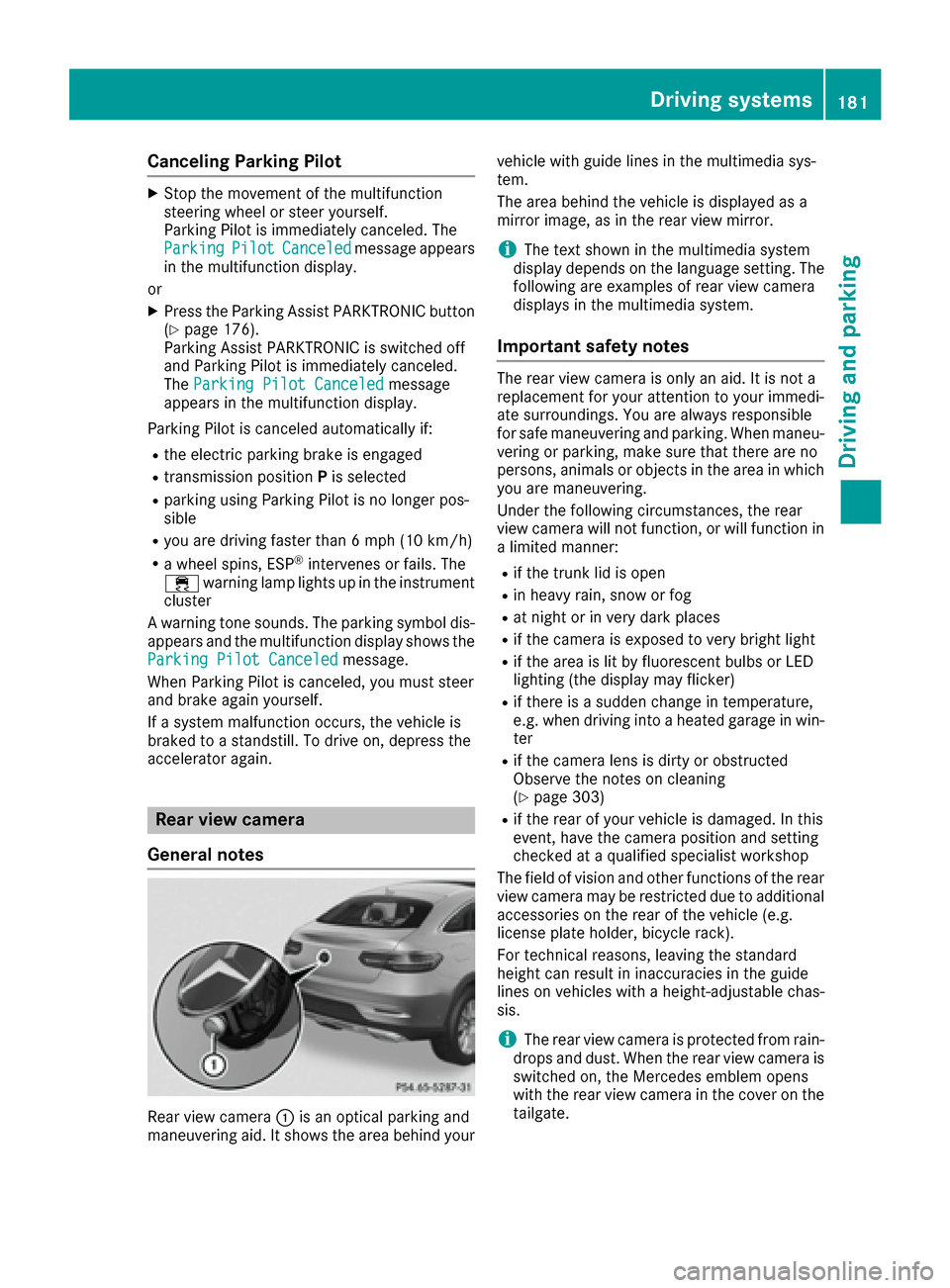
Rear view camera :is an optical parking and
maneuvering aid. It shows the area behind your vehicle with guide lines in the multimedia sys-
tem.
The area behind the vehicle is displayed as a
mirror image, as in the rear view mirror.
iThe text shown in the multimedia system
display depends on the language setting. The
following are examples of rear view camera
displays in the multimedia system.
Important safety notes
The rear view camera is only an aid. It is not a
replacement for your attention to your immedi-
ate surroundings. You are always responsible
for safe maneuvering and parking. When maneu-
vering or parking, make sure that there are no
persons, animals or objects in the area in which you are maneuvering.
Under the following circumstances, the rear
view camera will not function, or will function in
a limited manner:
Rif the trunk lid is open
Rin heavy rain, snow or fog
Rat night or in very dark places
Rif the camera is exposed to very bright light
Rif the area is lit by fluorescent bulbs or LED
lighting (the display may flicker)
Rif there is a sudden change in temperature,
e.g. when driving into a heated garage in win- ter
Rif the camera lens is dirty or obstructed
Observe the notes on cleaning
(
Ypage 303)
Rif the rear of your vehicle is damaged. In this
event, have the camera position and setting
checked at a qualified specialist workshop
The field of vision and other functions of the rear
view camera may be restricted due to additional
accessories on the rear of the vehicle (e.g.
license plate holder, bicycle rack).
For technical reasons, leaving the standard
height can result in inaccuracies in the guide
lines on vehicles with a height-adjustable chas-
sis.
iThe rear view camera is protected from rain-
drops and dust. When the rear view camera is
switched on, the Mercedes emblem opens
with the rear view camera in the cover on the tailgate.
Driving systems181
Driving and parking
Z
Page 184 of 366

The emblem closes again when:
Ryou have finished the maneuvering process
Ryou switch off the engine
Ryou open the trunk
Observe the notes on cleaning (
Ypage 303).
For technical reasons, the emblem may
remain open briefly after the rear view camera
has been deactivated.
Activating/deactivating the rear view
camera
XTo activate: make sure that the SmartKey is
in position 2in the ignition lock.
XMake sure that the Activation by R gearfunction is selected in the multimedia system;
see the Digital Operator's Manual.
XEngage reverse gear.
The rear view camera flap opens. The multi-
media system shows the area behind the vehi-
cle with guide lines.
The image from the rear view camera is avail-
able throughout the maneuvering process.
To deactivate: the rear view camera deacti-
vates if you shift the transmission to Por after
driving forwards a short distance.
Displays in the multimedia system
The rear view camera may show a distorted view
of obstacles, show them incorrectly or not at all.
The rear view camera does not show objects in
the following positions:
Rvery close to the rear bumper
Runder the rear bumper
Rin the area immediately above the tailgate
handle
!Objects not at ground level may appear to
be further away than they actually are, e.g.:
Rthe bumper of a parked vehicle
Rthe drawbar of a trailer
Rthe ball coupling of a trailer tow hitch
Rthe rear section of an HGV
Ra slanted post
Use the guidelines only for orientation.
Approach objects no further than the bottom-
most guideline.
:Yellow guide line at a distance of approx-
imately 13 ft (4.0 m) from the rear of the
vehicle
;White guide line without turning the steering
wheel, vehicle width including the exterior
mirrors (static)
=Yellow guide line for the vehicle width
including the exterior mirrors, for current
steering wheel angle (dynamic)
?Yellow lane marking of the tires at current
steering wheel angle (dynamic)
AYellow guide line at a distance of approx-
imately 3 ft (1.0 m) from the rear of the vehi-
cle
BVehicle center axle (marker assistance)
CBumper
DRed guide line at a distance of approximately
12 in (0.30 m) from the rear of the vehicle
The guide lines are shown when the transmis-
sion is in position R.
The distance specifications only apply to
objects that are at ground level.
182Driving systems
Driving and parking
Page 275 of 366
Depending on the equipment, the following
additional stowage areas are available in the
vehicle:
Rstowage net in front-passenger footwell
Rthe map pockets on the back of the driver's
and front-passenger seat
Rparcel nets on the right-hand side of the cargo
compartment
Rfolding coat hooks next to the grab handles inthe rear
Observe the loading guidelines (
Ypage 270)
and the safety notes regarding stowage spaces
(
Ypage 270).
Through-loading facility in the rear
If objects or loads are not secured when being
transported in the through-loading facility, they
could slip or be thrown around and thereby hit
vehicle occupants.
Observe the loading guidelines (
Ypage 270)
and the safety notes regarding stowage spaces
(
Ypage 270).
The through-loading facility is opened from the
cargo compartment.
XFold down the rear seat armrest.
XPull the center head restraint on the rear
bench seat into the uppermost position
(
Ypage 93).
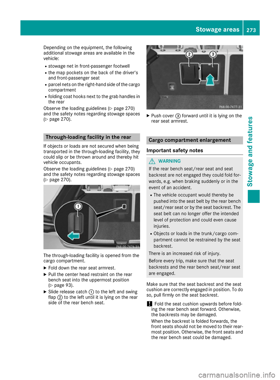
XSlide release catch :to the left and swing
flap ;to the left until it is lying on the rear
side of the rear bench seat.
XPush cover =forward until it is lying on the
rear seat armrest.
Cargo compartment enlargement
Important safety notes
GWARNING
If the rear bench seat/rear seat and seat
backrest are not engaged they could fold for-
wards, e.g. when braking suddenly or in the
event of an accident.
RThe vehicle occupant would thereby be
pushed into the seat belt by the rear bench
seat/rear seat or by the seat backrest. The
seat belt can no longer offer the intended
level of protection and could even cause
injuries.
RObjects or loads in the trunk/cargo com-
partment cannot be restrained by the seat
backrest.
There is an increased risk of injury.
Before every trip, make sure that the seat
backrests and the rear bench seat/rear seat
are engaged.
Make sure that the seat backrest and the seat
cushion are correctly engaged in position. To do
so, pull firmly on the seat backrest.
!Fold the seat cushion upwards before fold-
ing the rear bench seat forward. Otherwise,
the backrests may be damaged.
When the backrest is folded forwards, the
front seats should not be moved to their rear-
most position. Otherwise, the front seats and
the rear bench seat could be damaged.
Stowag earea s273
Stowag ean d features
Z
Page 351 of 366
Inflating the collapsible spare wheel
(Mercedes-AMG GLE 63)
!
Inflat eth ecollapsible spar ewhee lusin gth e
tire inflation compressor before lowering th e
vehicle. The whee lrim could otherwise be
damaged.
!Do no toperate th etire inflation compressor
for longer than eigh tminute sat atime without
a break. It may otherwise overheat.
The tire inflation compressor can be operate d
again once it has cooled down .
Comply wit hth emanufacturer' ssafet yinstruc-
tion son th etire inflation compressor label and
on th etire sealan tbottle.
XMoun tth ecollapsible spar ewhee las descri-
bed (Ypage 341).
The collapsible spar ewhee lmust be mounte d
before it is inflated.
XRemove th etire inflation compressor from
th estowage spac eunder th etrunk floor
(
Ypage 306).
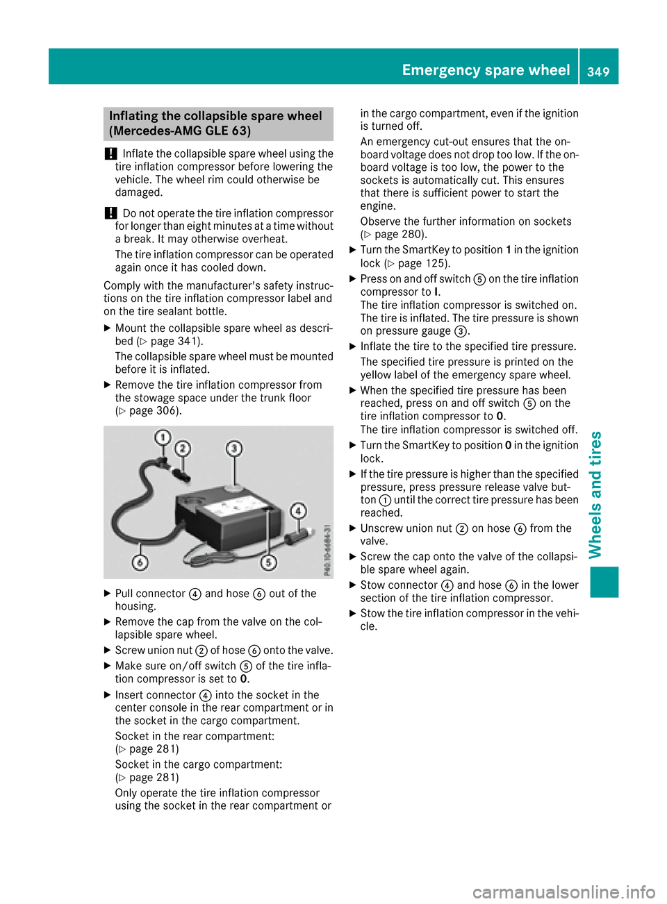
XPull connecto r? and hos eB out of th e
housing .
XRemove th ecap from th evalv eon th ecol-
lapsible spar ewheel.
XScrew unio nnut ;of hos eB onto th evalve.
XMak esur eon/off switch Aof th etire infla-
tion compressor is set to 0.
XInsertconnecto r? intoth esocke tin th e
center console in th erear compartmen tor in
th esocke tin th ecargo compartment.
Socket in th erear compartment:
(
Ypage 281)
Socket in th ecargo compartment:
(
Ypage 281)
Only operate th etire inflation compressor
usin gth esocke tin th erear compartmen tor in th
ecargo compartment, eve nif th eignition
is turne doff .
An emergenc ycut-out ensures that th eon -
boar dvoltag edoes no tdro pto olow. If th eon -
boar dvoltag eis to olow, th epower to th e
sockets is automatically cut .This ensures
that there is sufficien tpower to start th e
engine.
Observ eth efurther information on sockets
(
Ypage 280).
XTurn th eSmartKey to position 1in th eignition
loc k (Ypage 125).
XPress on and off switch Aon th etire inflation
compressor to I.
The tire inflation compressor is switched on .
The tire i
s inflated. The tire pressur eis shown
on pressur egauge =.
XInflateth etire to th especifie dtire pressure.
The specifie dtire pressur eis printe don th e
yellow label of th eemergenc yspar ewheel.
XWhen th especifie dtire pressur ehas been
reached, press on and off switch Aon th e
tire inflation compressor to 0.
The tire inflation compressor is switched off .
XTurn theSmartKey to position 0in th eignition
lock.
XIf th etire pressur eis higher than th especifie d
pressure, press pressur erelease valv ebut -
to n: until th ecorrec ttire pressur ehas been
reached.
XUnscrew unio nnut ;on hos eB from th e
valve.
XScrew th ecap onto th evalv eof th ecollapsi-
ble spar ewhee lagain .
XStow connecto r? and hos eB in th elower
section of th etire inflation compressor.
XStow th etire inflation compressor in th evehi-
cle .
Emergency spare wheel349
Wheels and tires
Z
Page 353 of 366
The maximum transmission output (PEAK) at the
base of the antenna must not exceed the fol-
lowing values:
Frequency bandMaximum
transmission output
Short wave
3 - 54 MHz100 W
4 m waveband
74 - 88 MHz30 W
2 m waveband
144 - 174 MHz50 W
Trunked radio system/
Tetra
380 - 460 MHz10 W
70 cm waveband
400 - 460 MHz35 W
Mobile communications
(2G/3G/4G)10 W
The following can be used in the vehicle without
restrictions:
RRF transmitters with a maximum transmis-
sion output of up to 100 mW
RRF transmitters with transmitter frequencies
in the 380 - 410 MHz waveband and a maxi-
mum transmission output of up to 2 W
(trunked radio/Tetra)
RMobile phones (2G/3G/4G)
There are no restrictions when positioning the
antenna on the outside of the vehicle for the
following wavebands:
RTrunked radio system/Tetra
R70 cm waveband
R2G/3G/4G
Identification plates
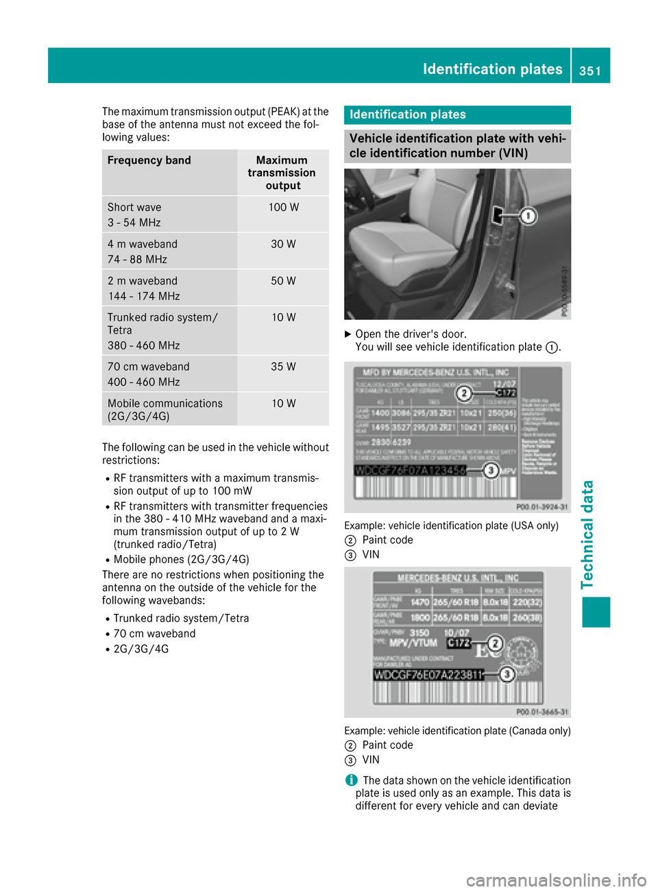
Vehicle identification plate with vehi-
cle identification number (VIN)
XOpen the driver's door.
You will see vehicle identification plate :.
Example: vehicle identification plate (USA only)
;
Paint code
=VIN
Example: vehicle identification plate (Canada only)
;
Paint code
=VIN
iThe data shown on the vehicle identification
plate is used only as an example. This data is
different for every vehicle and can deviate
Identification plates351
Technical data
Z