2017 MERCEDES-BENZ GLE43AMG SUV reset
[x] Cancel search: resetPage 220 of 366

XPress the:or9 button to select Noor
Yes.
XPress ato confirm the selection.
If you select Yes, the multifunction display
shows a confirmation message.
If you want to reset the Daytime Running
Lightsfunction in theLightsubmenu, you
must turn the SmartKey to position 1in the igni-
tion lock.
AMG menu (Mercedes-AMG vehicles)
Warm-up
:Digital speedometer
;Gear indicator
=Upshift indicator
?Engine oil temperature
ACoolant temperature
BTransmission oil temperature
XPress the =or; button on the steering
wheel to select the AMGmenu.
Upshift indicator: upshift indicatorUp=
indicates that the engine has reached the
overrevving range when in the manual drive
program.
Engine/transmission oil temperature:
when the engine and transmission are at nor-
mal operating temperature, oil tempera-
ture ?and Bare displayed in white in the
multifunction display.
If the multifunction display shows oil temper-
ature ?orB in blue, the engine or the
transmission are not yet at normal operating
temperature. Avoid driving at full engine out-
put during this time.
SETUP
:Engine mode (Comfort/Sport/Sport +)
;Suspension setting Comfort/Sport/
Sport +
=Transmission position D/M
?ESP®mode (ON/OFF)
SETUP displays the following information/func- tions:
Rthe digital speedometer
Rthe gear indicator
Rthe engine mode
Rthe suspension mode
Rthe transmission position
Rthe ESP®(Electronic Stability Program) mode
XPress the =or; button on the steering
wheel to select the AMGmenu.
XPress the9button repeatedly until SETUP
is displayed.
RACETIMER
Displaying and starting RACETIMER
The RACETIMER is only intended for use on a
closed race circuit. Do not use the function on
public roads.
:Lap
;RACETIMER
218Menus and submenus
On-board computer and displays
Page 221 of 366

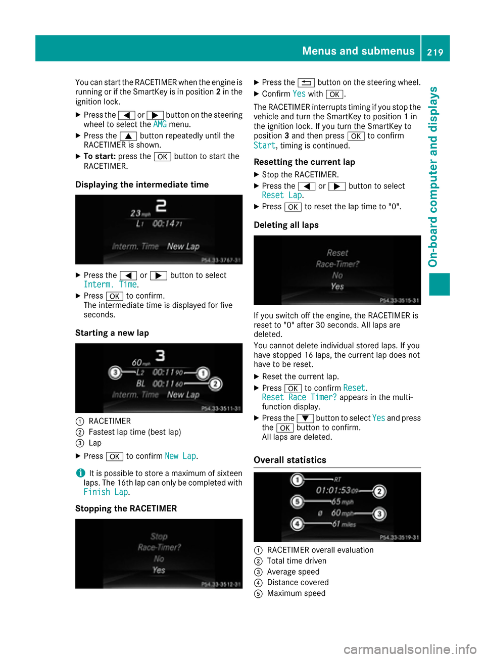
You can start the RACETIMER when the engine is
running or if the SmartKey is in position2in the
ignition lock.
XPress the =or; button on the steering
wheel to select the AMGmenu.
XPress the9button repeatedly until the
RACETIMER is shown.
XTo start: press the abutton to start the
RACETIMER.
Displaying the intermediate time
XPress the =or; button to select
Interm. Time.
XPress ato confirm.
The intermediate time is displayed for five
seconds.
Starting a new lap
:RACETIMER
;Fastest lap time (best lap)
=Lap
XPress ato confirm New Lap.
iIt is possible to store a maximum of sixteen
laps. The 16th lap can only be completed with
Finish Lap
.
Stopping the RACETIMER
XPress the %button on the steering wheel.
XConfirm Yeswitha.
The RACETIMER interrupts timing if you stop the
vehicle and turn the SmartKey to position 1in
the ignition lock. If you turn the SmartKey to
position 3and then press ato confirm
Start
, timing is continued.
Resetting the current lap
XStop the RACETIMER.
XPress the =or; button to select
Reset Lap.
XPress ato reset the lap time to "0".
Deleting all laps
If you switch off the engine, the RACETIMER is
reset to "0" after 30 seconds. All laps are
deleted.
You cannot delete individual stored laps. If you
have stopped 16 laps, the current lap does not
have to be reset.
XReset the current lap.
XPress ato confirm Reset.
Reset Race Timer?appears in the multi-
function display.
XPress the :button to select Yesand press
the a button to confirm.
All laps are deleted.
Overall statistics
:RACETIMER overall evaluation
;Total time driven
=Average speed
?Distance covered
AMaximum speed
Menus and submenus219
On-board computer and displays
Z
Page 300 of 366

ASSYST PLUS
Service message
The ASSYSTPLU Sservic einterval display
inform syou of th enext servic edue date.
Information on th etyp eof servic eand servic e
intervals (see th eseparat eMaintenance Book -
let).
You can obtain further information from an
authorize dMercedes-Benz Cente ror at
http://www.mbusa.co m(US Aonly).
iThe ASSYS TPLU Sservic einterval display
does no tsho wany information on th eengin e
oil level. Observ eth enote son th eengin eoil
level (
Ypage 295).
The multifunction display shows aservic emes -
sage for several seconds, e.g. :
RService Ain .. Day s
RService ADue
RServic e AOverdu eby .. Day s
Dependingon th eoperating condition sof th e
vehicle, th eremaining time or distanc euntil th e
next servic edue dat eis displayed.
The lette rA
or B,possibl yin connection wit h a
number or another letter, shows th etyp eof ser -
vice. A
stand sfor aminor servic eand Bfora
major service.
You can obtain further information from an
authorize dMercedes-Benz Center.
The ASSYS TPLU Sservic einterval display does
no ttak eint oaccoun tany periods of time during
whic hth ebattery is disconnected.
Maintainin gth etime-dependen tservic esched-
ule:
XNot edown th eservic edue dat edisplayed in
th emultifunction display before disconnect -
ing th ebattery.
or
XAfte rreconnecting th ebattery, subtrac tth e
battery disconnection periods from th eser -
vic edat eshown on th edisplay.
Hiding a service message
XPress th e% ora buttonon th esteering
wheel.
Displaying service messages
XSwitc hon th eignition .
XPress th e= or; buttonon th esteering
whee lto select th eServ.menu.
XPress th e9 or: buttonto select th e
ASSYSTPLU Ssubmen uand confirm by press-
ing th ea button.
The servic edue dat eappear sin th emulti-
function display.
Infor mation about Service
Resetting the ASSYST PLUS service
interval display
!If th eASSYS TPLU Sservic einterval display
has been inadvertentl yreset ,this setting can
be correcte dat aqualified specialist work-
shop.
Hav eservic ewor kcarrie dout as described in
th eMaintenance Booklet .This may otherwise
lead to increased wear and damag eto th e
major assemblies or th evehicle.
A qualified specialist workshop ,e.g. an author-
ized Mercedes-Benz Center, will reset th e
ASSYS TPLU Sservic einterval display after th e
servic ewor khas been carrie dout .You can also
obtain further information on maintenance
work, for example.
Special service requirements
The specifie dmaintenance interval takes only
th enormal operation of th evehicl eint o
account. Under arduous operating condition sor
increased load on th evehicle, maintenance
wor kmus tbe carrie dout mor efrequently, for
example:
Rregular cit ydrivin gwit hfrequen tintermediat e
stops
Rif th evehicl eis primarily used to travel short
distances
Ruse in mountainous terrain or on poor road
surfaces
Rif th eengin eis often lef tidlin gfor lon gperiods
Under these or similar conditions, have, for
example, th eair filter, engin eoil and oil filter
replace dor changed mor efrequently. Under
arduous operating conditions, th etires mus tbe
checke dmor eoften .Further information can be
298ASSYST PLUS
Maintenance and care
Page 315 of 366

The vehicle will then use very little energy, thus
conserving battery power.
If the power supply has been interrupted, e.g. ifyou reconnect the battery, you will have to:
Rset the clock; see the Digital Operator's Man-
ual
On vehicles with a multimedia system and
navigation system, the clock is set automati-
cally.
Rreset the function for folding the exterior mir-
rors in/out automatically, by folding the mir-
rors out once (
Ypage 100).
Charging the 12 V battery
GWARNING
During charging and jump-starting, explosive
gases can escape from the battery. There is a risk of an explosion.
Particularly avoid fire, open flames, creating
sparks and smoking. Ensure there is sufficient
ventilation while charging and jump-starting.
Do not lean over a battery.
GWARNING
Battery acid is caustic. There is a risk of injury.
Avoid contact with skin, eyes or clothing. Do
not inhale any battery gases. Do not lean over
the battery. Keep children away from batter-
ies. Wash away battery acid immediately with
plenty of clean water and seek medical atten-
tion.
GWARNING
A discharged battery can freeze at tempera-
tures below freezing point. When jump-start-
ing the vehicle or charging the battery, gases
can escape from the battery. There is a risk of an explosion.
Allow the frozen battery to thaw out before
charging it or jump-starting.
!Only use battery chargers with a maximum
charging voltage of 14.8 V.
!Only charge the battery using the jump-
starting connection point.
The jump-starting connection point is in the
engine compartment (
Ypage 313).
XOpen the hood.
XConnect the battery charger to the positive
terminal and ground point in the same order
as when connecting the donor battery in the
jump-starting procedure (
Ypage 313).
Keep away from fire and open flames. Do not
lean over a battery. Never charge the battery if it
is still installed in the vehicle, unless you use a
battery charger which has been tested and
approved by Mercedes-Benz. A battery charger
unit specially adapted for Mercedes-Benz vehi-
cles and tested and approved by Mercedes-
Benz is available as an accessory. It permits the
charging of the battery in its installed position.
Contact an authorized Mercedes-Benz Center
for further information and availability. Read the
battery charger's operating instructions before
charging the battery.
If, at low temperatures, the indicator lamps/
warning lamps in the instrument cluster do not
light up, it is highly likely that the discharged
battery has frozen. In this case you may neither
jump-start the vehicle nor charge the battery.
The service life of a thawed-out battery may be
shorter. The starting characteristics can be
impaired, particularly at low temperatures. Have
the thawed-out battery checked at a qualified
specialist workshop.
Jump-starting
For the jump-starting procedure, use only the jump-starting connection point in the engine com-
partment, consisting of a positive terminal and a ground point.
GWARNING
Battery acid is caustic. There is a risk of injury.
Jump-starting313
Breakdown assistance
Z
Page 319 of 366

When towing, the differential locks must not
be switched on. The transmission may other-
wise be damaged.
!The vehicle can be towed a maximum of
30 miles (50km). The towing speed of 30 mph (50 km/h) must not be exceeded.
If the vehicle has to be towed more than
30 miles (50km), the entire vehicle must be
raised and transported.
It is better to have the vehicle transported than
to have it towed away.
If the vehicle has suffered transmission damage,
have it transported on a transporter or trailer.
The automatic transmission must be in position N when the vehicle is being towed.
The battery must be connected and charged.
Otherwise, you:
Rcannot turn the SmartKey to position 2in the
ignition lock
Rcannot release the electric parking brake
Rcannot shift the automatic transmission to
position N
Disarm the automatic locking feature before the
vehicle is towed (
Ypage 216). You could other-
wise be locked out when pushing or towing the
vehicle.
Installing/removing the towing eye
Installing the towing eye
The brackets for the screw-in towing eye are
located in the bumpers. They are at the front and
rear behind covers :;.
XRemove the towing eye from the vehicle tool
kit (Ypage 306).
XPress the mark on cover :or; inwards in
the direction of the arrow.
XTake cover :or; off the opening.
XScrew in the towing eye clockwise as far as it
will go and tighten it.
Removing the towing eye
XUnscrew and remove the towing eye.
XFront cover: position left-hand side of
cover :in the bumper and press it in on the
right-hand side until it engages.
XRear cover: position top of cover ;in the
bumper and press it in at the bottom until it
engages.
XPlace the towing eye in the vehicle tool kit.
Towing a vehicle with both axles on
the ground
The automatic transmission automatically shifts
to position Pwhen you open the driver's or front-
passenger door or when you remove the Smart-
Key from the ignition lock.
In order to ensure that the automatic transmis-
sion stays in position Nwhen towing the vehicle,
you must observe the following points:
XMake sure that the vehicle is stationary.
XTurn the SmartKey to position 2in the ignition
lock.
XDepress and hold the brake pedal.
XShift the automatic transmission to position
N .
XLeave the SmartKey in position 2in the igni-
tion lock.
XRelease the brake pedal.
XRelease the electric parking brake.
XSwitch on the hazard warning lamps
(Ypage 106).
In order to signal a change of direction when
towing the vehicle with the hazard warning
lamps switched on, use the combination switch
as usual. In this case, only the indicator lamps
for the direction of travel flash. After resetting
Towing and tow-starting317
Breakdown assistance
Z
Page 327 of 366

Further information on tire pressures can be
obtained at a qualified specialist workshop.
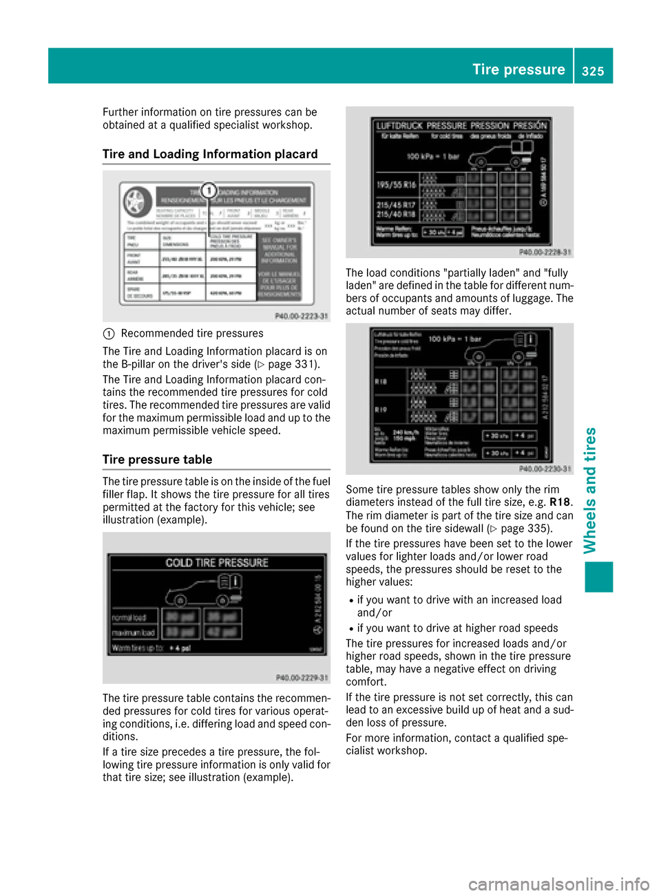
Tire and Loading Information placard
:Recommended tire pressures
The Tire and Loading Information placard is on
the B-pillar on the driver's side (
Ypage 331).
The Tire and Loading Information placard con-
tains the recommended tire pressures for cold
tires. The recommended tire pressures are valid
for the maximum permissible load and up to the
maximum permissible vehicle speed.
Tire pressure table
The tire pressure table is on the inside of the fuel
filler flap. It shows the tire pressure for all tires
permitted at the factory for this vehicle; see
illustration (example).
The tire pressure table contains the recommen-
ded pressures for cold tires for various operat-
ing conditions, i.e. differing load and speed con-
ditions.
If a tire size precedes a tire pressure, the fol-
lowing tire pressure information is only valid for that tire size; see illustration (example).
The load conditions "partially laden" and "fully
laden" are defined in the table for different num-
bers of occupants and amounts of luggage. The
actual number of seats may differ.
Some tire pressure tables show only the rim
diameters instead of the full tire size, e.g. R18.
The rim diameter is part of the tire size and can
be found on the tire sidewall (
Ypage 335).
If the tire pressures have been set to the lower
values for lighter loads and/or lower road
speeds, the pressures should be reset to the
higher values:
Rif you want to drive with an increased load
and/or
Rif you want to drive at higher road speeds
The tire pressures for increased loads and/or
higher road speeds, shown in the tire pressure
table, may have a negative effect on driving
comfort.
If the tire pressure is not set correctly, this can
lead to an excessive build up of heat and a sud-
den loss of pressure.
For more information, contact a qualified spe-
cialist workshop.
Tire pressure325
Wheels and tires
Z