2017 MERCEDES-BENZ GLC SUV tow bar
[x] Cancel search: tow barPage 8 of 374

Replacingbulbs ............................ .118
Bag hook ............................................ 284
Ball coupling
Installing ........................................ 204
Removing ....................................... 206
BAS (Brake Assist System) ................. 65
BAS PLUS with Cross-Traffic Assist
(Brake Assist PLUS with Cross-
Traffic Assist)
Function/notes ................................ 66
Important safety notes .................... 66
Battery (SmartKey)
Checking .......................................... 80
Important safety notes .................... 80
Replacing ......................................... 80
Battery (vehicle)
Charging ........................................ 327
Display message ............................ 241
Important safety notes .................. 325
Jump starting ................................. 328
Blind Spot Assist
Activating/deactivating (on-
board computer) ............................ 221
Display message ............................ 246
Notes/function .............................. 193
see Active Blind Spot Assist
Blootooth
®
Connecting a different mobile
phone ............................................ 276
BlueTEC
see DEF
Bluetooth
®
Searching for a mobile phone ........2 75
see also Digital Operator's Man-
ual ..................................................2 68
Telephony ...................................... 275
Brake Assist
see BAS (Brake Assist System)
Brake fluid
Display message ............................ 233
Notes ............................................. 368
Brake force distribution
see EBD (electronic brake force
distribution)
Brake linings
Display message ............................ 233 Brakes
ABS ..................................................6 5
Adaptive Brake Assist ...................... 69
BAS .................................................. 65
BAS PLUS with Cross-Traffic
Assist ............................................... 66
Brake fluid (notes) ......................... 368
Display message ............................ 228
EBD .................................................. 73
Hill start as sist ............................... 136
HO
LD function ............................... 171
Important safety notes .................. 159
Maintenance .................................. 160
Parking brake ................................ 155
Riding tips ...................................... 159
Warning lamp ................................. 258
Breakdown
Where will I find...? ........................ 319
see Flat tire
see Towing away
Brightness control (instrument
cluster lighting) ................................... 35
Buttons on the steering wheel ......... 209
C
California
Important notice for retail cus-
tomers and lessees .......................... 28
Calling up a malfunction
see Display messages
Calling up the climate control bar
Multimedia system ........................ 272
Calling up the climate control
menu
Multimedia system ........................ 272
Camera
see 360° camera
see Rear view camera
Car
see Vehicle
Care
360° camera ................................. 316
Car wash ........................................ 311
Carpets .......................................... 318
Display ........................................... 316
Exhaust pipe .................................. 316
Exterior lights ................................ 315
6Index
Page 9 of 374

General notes ................................ 311
Interior ...........................................316
Matte finish ................................... 314
Paint .............................................. 313
Plastic trim ....................................3 17
Power washer ................................ 313
Rear view camera .......................... 316
Roof lining ...................................... 318
Seat belt ........................................ 318
Seat cover ..................................... 317
Selector lever ................................ 317
Sensors ......................................... 315
Side running board ........................ 315
Steering wheel ............................... 317
Trim pieces ....................................3 17
Washing by hand ........................... 312
Wheels ...........................................3 14
Windows ........................................ 314
Wiper blades .................................. 315
Wooden trim .................................. 317
Cargo compartment
Opening/closing (from outside,
HANDS-FREE ACCESS) .................... 87
Plug-in module (telescopic rods) .... 287
Cargo compartment cover
Important safety notes .................. 285
Notes/how to use ......................... 285
Cargo compartment enlargement ... 281
Cargo compartment floor
Important safety notes .................. 288
Opening/closing ............................ 288
Stowage well (under) ..................... 288
Cargo compartment plug-in mod-
ule (telescope bars) .......................... 287
Cargo net
Attaching ....................................... 286
Important safety information ......... 285
Cargo tie down rings ......................... 284
CD
see also Digital Operator's Man-
ual ..................................................2 68
CD player (on-board computer) ........217
Center console
Lower section .................................. 40
Upper secti
on .................................. 38
Central locking
Locking/unlocking (SmartKey) ........7 7Change of address
.............................. 29
Change of ownership .......................... 29
Changing the media source .............216
Charge-air pressure (on-board
computer, Mercedes-AMG vehi-
cles) .................................................... 224
Child
Restraint system .............................. 60
Child seat
Forward-facing restraint system ...... 63
LATCH-type (ISOFIX) child seat
anchors ............................................ 61
On the front-passenger seat ............ 62
Rearward-facing restraint system .... 62
Top Tether ....................................... 61
Child-proof locks
Important safety notes .................... 63
Rear doors ....................................... 64
Children
Special seat belt retractor ............... 59
Children in the vehicle
Important safety notes .................... 59
Cigarette lighter ................................ 292
Cleaning
Mirror turn signal ........................... 315
Trailer tow hitch ............................. 316
Climate control
Control panel for dual-zone auto-
matic climate control ..................... 123
Controlling automatically ............... 125
Cooling with air dehumidification .. 125
Cooling with air dehumidification
(multimedia system) ...................... 273
Defrosting the windows ................. 127
Defrosting the windshield .............. 126
ECO start/stop function ................ 124
General notes ................................ 123
Indicator lamp ................................ 125
Ionization ....................................... 129
Ionization (multimedia system) ...... 273
Notes on using the automatic cli-
mate control .................................. 124
Overview ........................................ 272
Overview of systems ...................... 123
Perfume atomizer .......................... 128
P
erfume atomizer (multimedia
system) .......................................... 272
Index7
Page 25 of 374

Tow-startingEmergency engine starting ............ 333
Important safety notes .................. 330
Towing a trailer
Axle load, permissible .................... 371
Cleaning the trailer tow hitch ......... 316
Coupling up a trailer ...................... 204
Decoupling a trailer ....................... 206
Driving tips .................................... 203
ESP
®(Electronic Stability Pro-
gram) ............................................... 73
Important safety notes .................. 202
Installing the ball coupling ............. 204
Lights display message .................. 239
Power supply ................................. 206
Pulling away with a trailer .............. 135
Removing the ball coupling ............ 206
Trailer loads ................................... 371
Towing away
Important safety guidelines ........... 330
Installing the towing eye ................ 331
Notes for 4MATIC vehicles ............ 333
Removing the towing eye ............... 332
Transporting the vehicle ................ 332
With both axles on the ground ....... 332
Towing eye ......................................... 320
Traffic reports
see also Digital Operator's Man-
ual .................................................. 268
Traffic Sign Assist
Display message ............................ 247
Function/notes ............................. 192
Important safety notes .................. 193
Instrument cluster display ............. 193
Trailer coupling
see Towing a trailer
Trailer loads and drawbar nose-
weights ............................................... 206
Trailer towing
Active Lane Keeping Assist ............ 202
Blind Spot Assist ............................ 195
Permissible trailer loads and
drawbar noseweights ..................... 206
Transfer case ..................................... 148
Transmission
Display message ............................ 253
see Automatic transmission Transmission oil
Temperature (on-board computer,
Mercedes-AMG vehi
cles) ............... 224
Transmission position display ......... 142
Transporting the vehicle .................. 332
Trim pieces (cleaning instruc-
tions) .................................................. 317
Trip computer (on-board com-
puter) .................................................. 213
Trip odometer
Calling up ....................................... 212
Resetting (on-board computer) ...... 214
Trunk
see Cargo compartment
Trunk load (maximum) ...................... 370
Turn signals
Display message ............................ 239
Replacing bulbs (front) ................... 117
Switching on/off ........................... 112
Two-way radio
Frequencies ................................... 362
Installation ..................................... 362
Transmission output (maximum) .... 362
Type identification plate
see Vehicle identification plate
U
UnlockingEmergency unlocking ....................... 84
From inside the vehicle (central
unlocking button) ............................. 83
USB devices
Connecting to the Media Inter-
face ............................................... 276
V
Vanity mirror (in the sun visor) ........ 291
Vehicle
Correct use ...................................... 31
Data acquisition ............................... 32
Display message ............................ 252
Electronics ..................................... 362
Equipment ....................................... 28
Individual settings .......................... 220
Limited Warranty ............................. 32
Loading .......................................... 346
Index23
Page 178 of 374

PARKTRONIC is only an aid. It is not a replace-
ment for your attention to your immediate sur-
roundings. You are always responsible for safe
maneuvering, parking and exiting a parking
space. Make sure that there are no persons,
animals or objects in the maneuvering area
while maneuvering and parking in/leaving park-
ing spaces.
!When parking, pay particular attention to
objects above or below the sensors, such as
flower pots or trailer drawbars. PARKTRONIC
does not detect such objects when they are in
the immediate vicinity of the vehicle. You
could damage the vehicle or the objects.
The sensors may not detect snow and other
objects that absorb ultrasonic waves.
Ultrasonic sources such as an automatic car
wash, the compressed-air brakes on a truck
or a pneumatic drill could cause PARKTRONIC
to malfunction.
PARKTRONIC may not function correctly on
uneven terrain.
!Remove the detachable ball coupling if the
trailer tow hitch is not required. PARKTRONIC
measures the minimum detection range to an
obstacle from the bumper, not the ball cou-
pling.
PARKTRONIC is activated automatically when
you:
Rswitch on the ignition
Rshift the transmission to position h,kor
i
PARKTRONIC is deactivated at speeds above
11 mph (18 km/ h). It is reactivated at lower
speeds.
PARKTRONIC is deactivated for the rear area
when you establish an electrical connection
between your vehicle and a trailer.
Range of the sensors
PARKTRONIC does not take objects into con-
sideration that are:
Rbelow the detection range, e.g. people, ani-
mals or objects.
Rabove the detection range, for example over- hanging loads, truck overhangs or loading
ramps.
:Sensors in the front bumper, left-hand side
(example)
:Approx. 24 in (approx. 60 cm) (corners)
;Approx. 32 in (approx. 80 cm) (corners)
=Approx. 48 in (approx. 120 cm) (center)
?Approx. 40 in (approx. 100 cm) (center)
The sensors must be free from dirt, ice or slush.
They can otherwise not function correctly. Clean
the sensors regularly, taking care not to scratch
or damage them (
Ypage 315).
Minimum distance
CenterApprox. 8 in (approx. 20 cm)
CornersApprox. 6 in (approx. 15 cm)
176Driving systems
Driving and parking
Page 185 of 374

Rif there is a sudden change in temperature,
e.g. when driving into a heated garage in win-ter
Rif the camera lens is dirty or obstructed
Observe the notes on cleaning
(
Ypage 316)
Rif the rear of your vehicle is damaged. In this
case, have the camera position and setting
checked at a qualified specialist workshop
The field of vision and other functions of the rear
view camera may be restricted due to additional
accessories on the rear of the vehicle (e.g.
license plate holder, rear bicycle rack).
The rear view camera is protected from rain-
drops and dust by means of a flap. When the rear view camera is activated, this flap opens.
The flap closes again when:
Ryou have finished the maneuvering process
Ryou switch off the engine
Ryou open the cargo compartment
Observe the notes on cleaning (
Ypage 316).
For technical reasons, the flap may remain open
briefly after the rear view camera has been
deactivated.
Activating/deactivating the rear view
camera
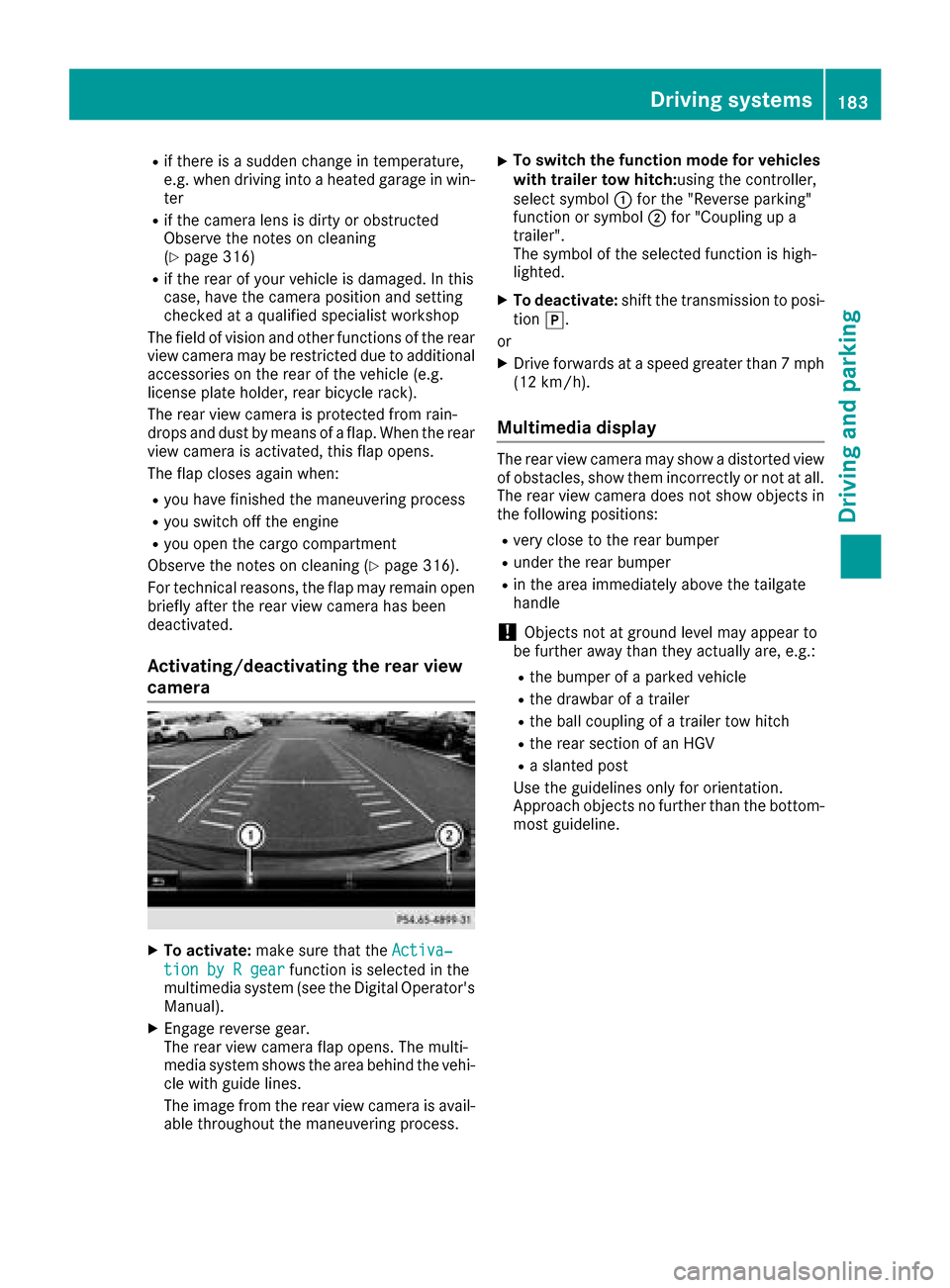
XTo activate: make sure that the Activa‐
tion by R gearfunction is selected in the
multimedia system (see the Digital Operator's
Manual).
XEngage reverse gear.
The rear view camera flap opens. The multi-
media system shows the area behind the vehi-
cle with guide lines.
The image from the rear view camera is avail- able throughout the maneuvering process.
XTo switch the function mode for vehicles
with trailer tow hitch: using the controller,
select symbol :for the "Reverse parking"
function or symbol ;for "Coupling up a
trailer".
The symbol of the selected function is high-
lighted.
XTo deactivate: shift the transmission to posi-
tion j.
or
XDrive forwards at a speed greater than 7 mph
(12 km/h).
Multimedia display
The rear view camera may show a distorted view
of obstacles, show them incorrectly or not at all.
The rear view camera does not show objects in
the following positions:
Rvery close to the rear bumper
Runder the rear bumper
Rin the area immediately above the tailgate
handle
!Objects not at ground level may appear to
be further away than they actually are, e.g.:
Rthe bumper of a parked vehicle
Rthe drawbar of a trailer
Rthe ball coupling of a trailer tow hitch
Rthe rear section of an HGV
Ra slanted post
Use the guidelines only for orientation.
Approach objects no further than the bottom-
most guideline.
Driving systems183
Driving and parking
Z
Page 188 of 374

"Coupling up a trailer" function
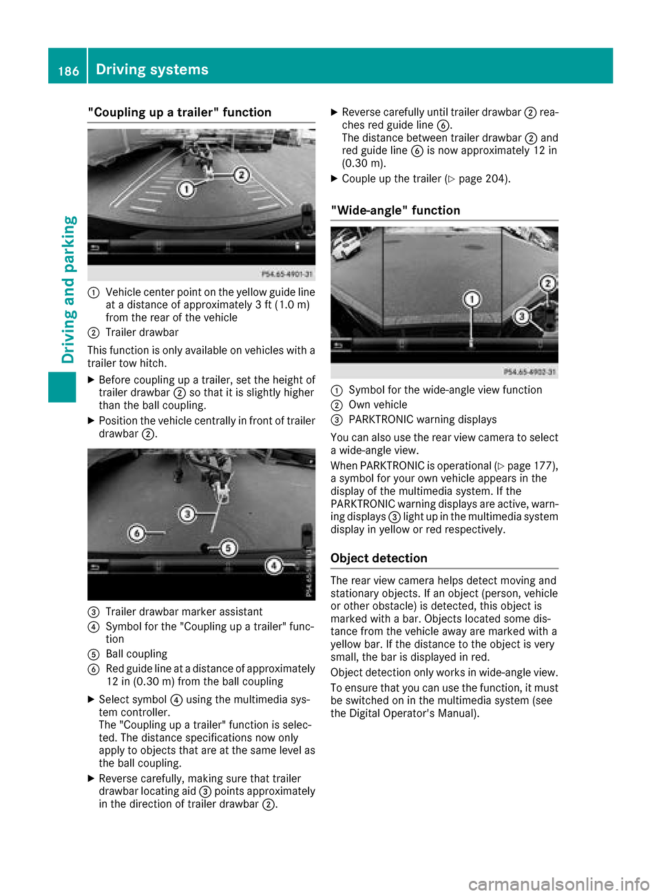
:Vehicle center point on the yellow guide line
at a distance of approximately 3 ft (1.0 m)
from the rear of the vehicle
;Trailer drawbar
This function is only available on vehicles with a
trailer tow hitch.
XBefore coupling up a trailer, set the height of
trailer drawbar ;so that it is slightly higher
than the ball coupling.
XPosition the vehicle centrally in front of trailer
drawbar ;.
=Trailer drawbar marker assistant
?Symbol for the "Coupling up a trailer" func-
tion
ABall coupling
BRed guide line at a distance of approximately
12 in (0.30 m) from the ball coupling
XSelect symbol ?using the multimedia sys-
tem controller.
The "Coupling up a trailer" function is selec-
ted. The distance specifications now only
apply to objects that are at the same level as
the ball coupling.
XReverse carefully, making sure that trailer
drawbar locating aid =points approximately
in the direction of trailer drawbar ;.
XReverse carefully until trailer drawbar ;rea-
ches red guide line B.
The distance between trailer drawbar ;and
red guide line Bis now approximately 12 in
(0.30 m).
XCouple up the trailer (Ypage 204).
"Wide-angle" function
:Symbol for the wide-angle view function
;Own vehicle
=PARKTRONIC warning displays
You can also use the rear view camera to select
a wide-angle view.
When PARKTRONIC is operational (
Ypage 177),
a symbol for your own vehicle appears in the
display of the multimedia system. If the
PARKTRONIC warning displays are active, warn-
ing displays =light up in the multimedia system
display in yellow or red respectively.
Object detection
The rear view camera helps detect moving and
stationary objects. If an object (person, vehicle
or other obstacle) is detected, this object is
marked with a bar. Objects located some dis-
tance from the vehicle away are marked with a
yellow bar. If the distance to the object is very
small, the bar is displayed in red.
Object detection only works in wide-angle view.
To ensure that you can use the function, it must
be switched on in the multimedia system (see
the Digital Operator's Manual).
186Driving systems
Driving and parking
Page 191 of 374

Rvery close to the exterior mirrors
Rin the transitional areas between the various
cameras in the virtual top view
!Objects not at ground level may appear to
be further away than they actually are, e.g.:
Rthe bumper of a parked vehicle
Rthe drawbar of a trailer
Rthe ball coupling of a trailer tow hitch
Rthe rear section of an HGV
Ra slanted post
Use the guidelines only for orientation.
Approach objects no further than the bottom-
most guideline.
Top view with picture from the rear view
camera
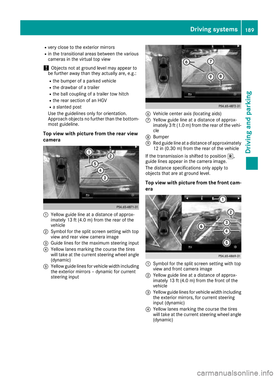
:Yellow guide line at a distance of approx-
imately 13 ft (4.0 m) from the rear of the
vehicle
;Symbol for the split screen setting with top
view and rear view camera image
=Guide lines for the maximum steering input
?Yellow lanes marking the course the tires
will take at the current steering wheel angle
(dynamic)
AYellow guide lines for vehicle width including
the exterior mirrors – dynamic for current
steering input
BVehicle center axis (locating aids)
CYellow guide line at a distance of approx-
imately 3 ft (1.0 m) from the rear of the vehi-
cle
DBumper
ERed guide line at a distance of approximately
12 in (0.30 m) from the rear of the vehicle
If the transmission is shifted to position k,
guide lines appear in the camera image.
The distance specifications only apply to
objects that are at ground level.
Top view with picture from the front cam-
era
:Symbol for the split screen setting with top
view and front camera image
;Yellow guide line at a distance of approx-
imately 13 ft (4.0 m) from the front of the
vehicle
=Yellow guide lines for vehicle width including
the exterior mirrors, for current steering
input (dynamic)
?Yellow lanes marking the course the tires
will take at the current steering wheel angle
(dynamic)
Driving systems189
Driving and parking
Z
Page 192 of 374

ARed guide lineat adistanc eof approximately
12 in (0.30m) from the front of the vehicle
BYellow guide line at a distance of approx-
imately 3 ft (1.0 m) fromthe front of the
vehicle
Top view and enlarged rear view
:Symbol for the split screen setting with top
view and rear view camera image enlarged
;Red guide line at a distance of approximately
12 in (0.30 m)from the rear of the vehicle
This view assists you in estimating the distance
to the vehicle behind you.
iThis setting can also be selected as an
enlarged front view.
Top view with image from the side cam-
eras
:Symbol for the top view and forward-facing
side camera setting
;Yellow guide line for the vehicle width
including the exterior mirrors (right side of
vehicle)
=Yellow guide line for the vehicle width
including the exterior mirrors (left side of
vehicle)
iYou can also select the side camera setting
for the rear-facing view.
"Coupling up a trailer" function
:Vehicle center point on the yellow guide line
at a distance of approximately 3 ft (1.0 m)
from the rear of the vehicle
;Trailer drawbar
=Red guide line at a distance of approximately
12 in (0.30 m) from the rear of the vehicle
XSet the height of trailer drawbar ;so that it
is slightly higher than the ball coupling.
XPosition the vehicle centrally in front of trailer
drawbar ;.
For technical reasons, the ball coupling Bof
the trailer tow hitch on the multimedia system
display is either only partially visible or not visi-
ble at all.
XSelect symbol ?using the controller.
The "Coupling up a trailer" function is selec-
ted. The distance specifications now only
apply to objects that are at the same level as
the ball coupling.
XReverse carefully, making sure that trailer
drawbar locating aid Apoints approximately
in the direction of the trailer drawbar.
190Driving systems
Driving and parking