2017 MERCEDES-BENZ GLA SUV clock
[x] Cancel search: clockPage 145 of 369
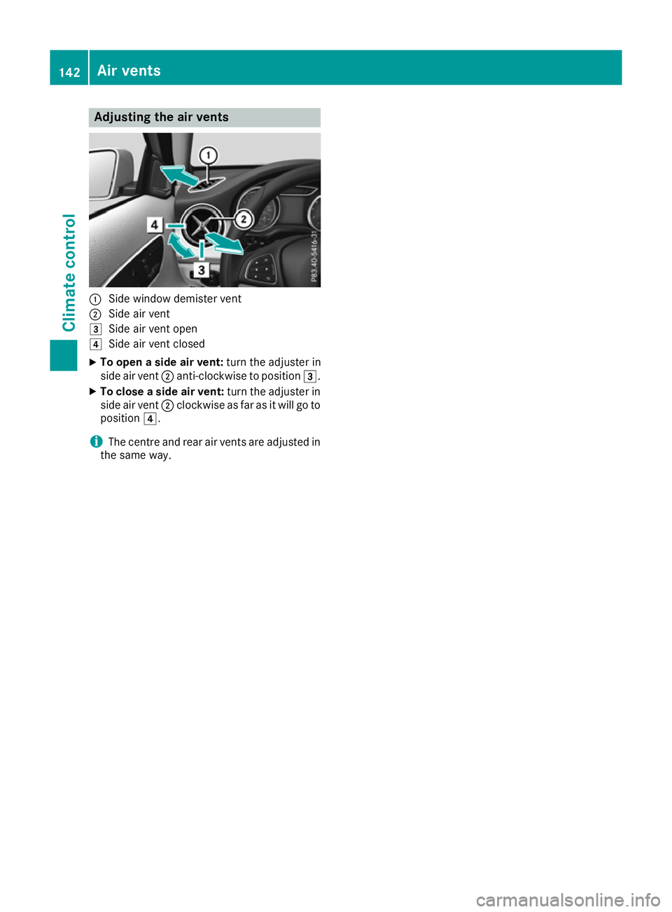
Adjusting the air vents
:
Side window demister vent
; Side air vent
3 Side air vent open
4 Side air vent closed
X To open a side air vent: turn the adjuster in
side air vent ;anti-clockwise to position 3.
X To close a side air vent: turn the adjuster in
side air vent ;clockwise as far as it will go to
position 4.
i The centre and rear air vents are adjusted in
the same way. 142
Air ventsClimate cont
rol
Page 167 of 369
Always touch the vehicle body before opening
the fuel filler flap or touching the fuel pump
nozzle. This discharges any electrostatic
charge that may have built up. G
WARNING
Vehicles with a diesel engine:
If you mix diesel fuel with petrol, the flash
point of this fuel mixture is lower than that of pure diesel fuel. When the engine is running,
components in the exhaust system may over-
heat unnoticed. There is a risk of fire.
Never refuel with petrol. Never add petrol to
diesel fuel.
! Do not use diesel to refuel vehicles with a
petrol engine. Do not switch on the ignition if you accidentally refuel with the wrong fuel.
Otherwise, the fuel will enter the fuel system.
Even small amounts of the wrong fuel can
result in damage to the fuel system and the
engine. Notify a qualified specialist workshop
and have the fuel tank and fuel lines drained
completely.
! Do not use petrol to refuel vehicles with a
diesel engine. Do not switch on the ignition if you accidentally refuel with the wrong fuel.
Otherwise, fuel can enter the fuel system.
Even small amounts of the wrong fuel could
result in damage to the fuel system and the
engine. The repair costs are high. Notify a
qualified specialist workshop and have the
fuel tank and fuel lines drained completely.
! Overfilling the fuel tank could damage the
fuel system.
! Take care not to spill any fuel on painted
surfaces. You could otherwise damage the
paintwork.
! Use a filter when adding fuel from a fuel can.
The fuel lines and/or the fuel injection system could otherwise be blocked by particles fromthe fuel can.
Do not get back into the vehicle during the refu-
elling process; Otherwise, electrostatic charge
could build up again.
If you overfill the fuel tank, some fuel may spray out when you remove the fuel pump nozzle.
Further information on fuel and fuel quality
(Y page 352). Refuelling
General information Observe the important safety notes
(Y
page 163).
The fuel filler flap is unlocked/locked automat-
ically when you unlock/lock the vehicle with the
key.
The position of the fuel filler cap is displayed
æ in the instrument cluster. The arrow next
to the filling pump indicates the side of the vehi- cle.
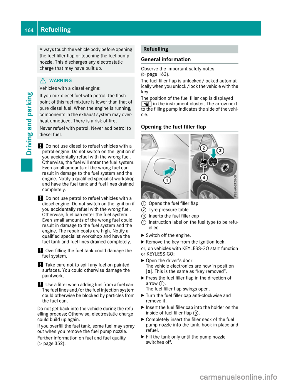
Opening the fuel filler flap :
Opens the fuel filler flap
; Tyre pressure table
= Inserts the fuel filler cap
? Instruction label on the fuel type to be refu-
elled
X Switch off the engine.
X Remove the key from the ignition lock.
or, on vehicles with KEYLESS-GO start function
or KEYLESS ‑GO:
X Open the driver's door.
The vehicle electronics are now in position
g. This is the same as “key removed”.
X Press the fuel filler flap in the direction of
arrow :.
The fuel filler flap swings open.
X Turn the fuel filler cap anti-clockwise and
remove it.
X Insert the fuel filler cap into the holder on the
inside of fuel filler flap =.
X Completely insert the filler neck of the fuel
pump nozzle into the tank, hook in place and
refuel.
X Fill the tank only until the pump nozzle
switches off. 164
RefuellingDriving an
d parking
Page 168 of 369
Vehicles with a diesel engine: the filler neck is
designed for refuelling at diesel filling pumps.
Do not add any more fuel after the pump stops
filling for the first time. Otherwise, fuel may leak out. Closing the fuel filler flap X
Replace the cap on the filler neck and turn
clockwise until it engages audibly.
X Close the fuel filler flap.
Close the fuel filler flap before locking the vehi-
cle. Problems with the fuel and fuel tank
Problem
Possible causes/consequences and
M MSolutions Fuel is leaking from the
vehicle. The fuel line or the fuel tank is faulty.
G WARNING
There is a risk of fire or explosion. X Apply the electric parking brake.
X Switch off the engine.
X Remove the key from the ignition lock.
or, on vehicles with KEYLESS-GO start function or KEYLESS ‑GO:
X Open the driver's door.
The vehicle electronics are now in position g. This is the same as
“key removed”.
X Do not restart the engine under any circumstances.
X Consult a qualified specialist workshop. The engine does not
start. The fuel tank of a vehicle with a diesel engine has been run completely
dry.
X Refuel the vehicle with at least 5 l of diesel.
X Turn the ignition on for approximately ten seconds (Y page 144).
X Start the engine continuously for a maximum of ten seconds until it
runs smoothly.
If the engine does not start: X Turn the ignition on again for a maximum of ten seconds
(Y page 144).
X Start the engine again continuously for a maximum of ten seconds
until it runs smoothly.
If the engine does not start after three attempts:
X Consult a qualified specialist workshop. The fuel filler flap cannot
be opened. The fuel filler flap is not unlocked.
X Unlock the vehicle (Y page 79). Refuelling
165Driving and parking Z
Page 217 of 369
Driving tips
R
Maintain a greater distance to the vehicle in
front than when driving without a trailer.
R Avoid braking abruptly. If possible, brake gen-
tly at first to allow the trailer to run on. Then,
increase the braking force rapidly.
R The values given for gradient-climbing capa-
bilities from a standstill refer to sea level.
When driving in mountainous areas, note that
the power output of the engine, and conse-
quently the vehicle's gradient-climbing capa-
bility from a standstill, decrease with increas- ing altitude.
If the trailer swings from side to side:
X Do not accelerate under any circumstances
X Do not countersteer
X Brake if necessary Folding out the ball coupling
Folding out the ball coupling G
WARNING
If the ball coupling is not correctly engaged,
the trailer can detach. There is a risk of an
accident.
Always engage the ball coupling as described. G
WARNING
If you release the ball coupling or it does not
engage correctly when folding in, it will swing out. Within pivoting range of the ball coupling,
there is an increased risk of an accident and
injury.
Only release the ball coupling if the pivoting
range is unobstructed. Always make sure that the ball coupling engages when folding in.
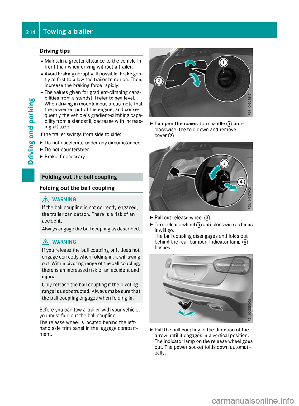
Before you can tow a trailer with your vehicle,
you must fold out the ball coupling.
The release wheel is located behind the left-
hand side trim panel in the luggage compart-
ment. X
To open the cover: turn handle:anti-
clockwise, the fold down and remove
cover ;. X
Pull out release wheel =.
X Turn release wheel =anti-clockwise as far as
it will go.
The ball coupling disengages and folds out
behind the rear bumper. Indicator lamp ?
flashes. X
Pull the ball coupling in the direction of the
arrow until it engages in a vertical position.
The indicator lamp on the release wheel goes out. The power socket folds down automati-
cally. 214
Towing a trailerDriving and pa
rking
Page 218 of 369
The multifunction display shows the
Check
Check
trailer hitch lock
trailer hitch lock display message until
the ball coupling is engaged.
X Remove the protective cap from the ball cou-
pling and store it in a safe place.
X Make sure that the ball of the ball coupling is
clean and that it is either greased or dry
(grease free), depending on the instructions
for the trailer.
Folding in the ball coupling G
WARNING
If you release the ball coupling or it does not
engage correctly when folding in, it will swing out. Within pivoting range of the ball coupling,
there is an increased risk of an accident and
injury.
Only release the ball coupling if the pivoting
range is unobstructed. Always make sure that the ball coupling engages when folding in.
i Fold the ball coupling in if you are not using
the trailer tow hitch.
X Make sure that the vehicle is stationary and
the trailer cables are disconnected.
X Place the protective cap on the ball coupling.
i The release wheel is located behind the left-
hand side trim panel in the luggage compart- ment.
X To open the cover: turn handle:anti-
clockwise, then fold down and remove
cover ;.
X Pull out release wheel =.
X Turn release wheel =anti-clockwise as far as
it will go.
The ball coupling disengages and folds out
behind the rear bumper. Indicator lamp ?
flashes.
X Press the ball coupling until it engages audibly
behind the bumper.
The indicator lamp on the release knob and
the message in the multifunction display go
out. Coupling up a trailer
X Make sure that the transmission is in position
j.
X Apply the electric parking brake.
X Position the trailer on a level surface behind
the vehicle.
X Couple up the trailer.
X Establish the electrical connection between
the vehicle and the trailer.
X Check that the trailer lighting system is work-
ing.
A connected trailer is only detected when the
electrical connection is established correctly
and when the lighting system is working prop- erly. The function of other systems, such as
ESP ®
or PARKTRONIC also depends on this. Uncoupling a trailer
G
WARNING
If you uncouple a trailer with an engaged over- run brake, you could trap your hand between
the vehicle and the trailer drawbar. This poses a risk of injury.
Do not uncouple a trailer with an engaged
overrun brake.
! Do not disconnect a trailer with an engaged
overrun brake. Otherwise, your vehicle could
be damaged by the rebounding of the overrun brake.
! Remove the installed adapter cable before
folding in the ball coupling. Otherwise, dam-
age may occur to the rear bumper and the
adapter cable.
X Make sure that the transmission is in position
P.
X Apply the electric parking brake.
X Secure the trailer against rolling away.
X Remove the trailer cable and decouple the
trailer. Trailer power supply
! You can connect accessories to the perma-
nent power supply up to a maximum of 240 W. Towing a trailer
215Driving and parking Z
Page 219 of 369
You cannot charge a trailer battery using the
power supply.
When it leaves the factory, your vehicle's trailer
socket is equipped with a permanent power
supply and a power supply that is switched on
via the ignition lock.
The permanent power supply is supplied via
trailer socket pin 9.
The power supply that is switched on via the
ignition lock is supplied via trailer socket pin 10.
The trailer's permanent power supply is
switched off in the event of low vehicle supply
voltage and after six hours at the latest.
You can find more information about fitting the
trailer electrics at a qualified specialist work-
shop.
X To switch the connected power supply on
or off: turn the key to position 2or 0respec-
tively (Y page 144). Failure check for LEDs
If LED lamps are fitted in the trailer, a malfunc-
tion message may appear in the multifunction
display even if there is no fault. The reason for
the error message may be that the current has
fallen below the minimum of 50 mA.
To ensure reliable operation of the failure indi-
cator, each LED chain in the trailer lighting must
be guaranteed a minimum current of 50 mA. Trailer with 7-pin connector
General notes Trailer with 7-pin connector:
you can connect
to the 13-pin socket on the ball coupling using
an adapter or, if necessary, an adapter cable.
Both can be obtained at a qualified specialist
workshop.
Fitting the adapter !
Make sure that there is sufficient cable play
so that the cable cannot become detached
when cornering.
! Remove the installed adapter cable before
folding in the ball coupling. Otherwise, dam-
age may occur to the rear bumper and the
adapter cable. X
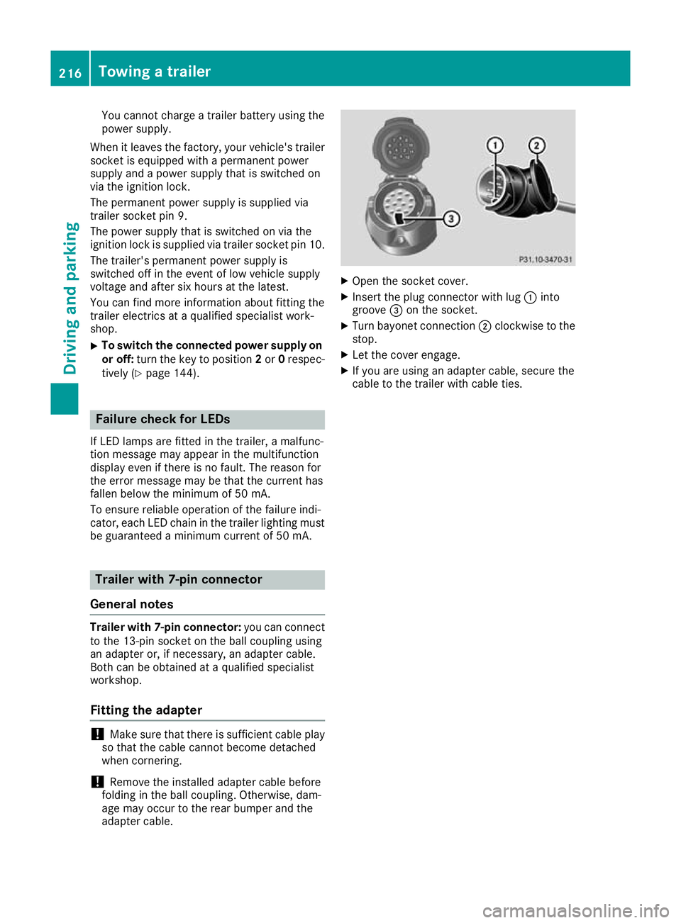
Open the socket cover.
X Insert the plug connector with lug :into
groove =on the socket.
X Turn bayonet connection ;clockwise to the
stop.
X Let the cover engage.
X If you are using an adapter cable, secure the
cable to the trailer with cable ties. 216
Towing a trailerDriving and parking
Page 220 of 369
Important safety notes
G
WARNING
If you operate information and communica-
tion equipment integrated in the vehicle when driving, you could be distracted from the traf-
fic situation. This could also cause you to lose control of the vehicle. There is a risk of an
accident.
Only operate this equipment when the traffic
situation permits. If you cannot be sure of this,
stop the vehicle paying attention to road and
traffic conditions and operate the equipment
with the vehicle stationary.
You must observe the legal requirements for the
country in which you are currently driving when operating the on-board computer. G
WARNING
If the instrument cluster has failed or mal-
functioned, you may not recognise function
restrictions relevant to safety. The operating
safety of your vehicle may be impaired. There is a risk of an accident.
Drive on carefully. Have the vehicle checked
at a qualified specialist workshop immedi-
ately.
The on-board computer shows only display mes- sages or warnings from certain systems on the
multifunction display. You should therefore
make sure your vehicle is operating safely at alltimes.
If the operating safety of your vehicle is
impaired, park the vehicle safely as soon as pos-
sible. Contact a qualified specialist workshop.
For an overview, see the instrument cluster illus-
tration (Y page 34). Displays and operation
Instrument cluster lighting
The light sensor in the instrument cluster auto-
matically controls the brightness of the multi-
function display. In daylight, the displays in the
instrument cluster are not illuminated. The lighting in the instrument cluster, in the dis-
plays and the controls in the vehicle interior can
be adjusted using the brightness control knob.
The brightness control knob is located on the
bottom left of the instrument cluster
(Y page 34).
X Turn the brightness control knob clockwise or
anti-clockwise.
If the light switch is set to the Ã,Tor
L position, the brightness is dependent
upon the brightness of the ambient light. Speedometer with segments
The speedometer is divided into segments on
vehicles with Distance Pilot DISTRONIC.
The segments in the speedometer indicate
which speed range is available.
R Variable speed limiter is activated
(Y page 178):
The segments light up from the start of the
scale to the selected speed limitation.
R Distance Pilot DISTRONIC is activated
(Y page 180):
One or two segments in the stored speed
range light up.
R Distance Pilot DISTRONIC detects a vehicle in
front moving more slowly than the stored
speed:
The segments between the speed of the vehi- cle in front and the stored speed light up. Rev counter
! Do not drive in the overrevving range. Doing
so will damage the engine.
The red band in the rev counter indicates the
engine's overrevving range.
The engine is limited within a range to protect
the engine when the red band is reached. Outside temperature display
You should pay special attention to road condi-
tions when temperatures are around freezing
point.
Bear in mind that the outside temperature dis-
play indicates the measured air temperature
and not the road surface temperature. Displays and operation
217On-board computer and displays Z
Page 232 of 369
Selecting permanent display
United Kingdom: this function is unavailable.
The Permanent display:
Permanent display: function allows you
to choose whether the multifunction display
always shows the outside temperature or the
speed.
The speed display is inverse to your speedome- ter.
X Press the =or; button on the steering
wheel to select the Settings
Settings menu.
X Press the :or9 button to select the
Instrument cluster Instrument cluster submenu.
X Press ato confirm.
X Press the :or9 button to select the
Permanent display:
Permanent display: function.
The current setting, outside temperature
outside temperature
or Dig. speedo [mph]:
Dig. speedo [mph]:, appears.
X Press the abutton to save the setting.
Lights Switching the daytime driving lights
on/off
The Daytime driving lights Daytime driving lights function can
only be switched on with the engine turned off.
X Press the =or; button on the steering
wheel to select the Settings
Settingsmenu.
X Press the :or9 button to select the
Lights
Lights submenu.
X Press ato confirm.
X Press the :or9 button to select the
Daytime driving lights
Daytime driving lights function.
If the Daytime
Daytime driving
drivinglights
lightsfunction has
been switched on, the cone of light and the
W symbol in the multifunction display are
shown in orange.
X Press the abutton to save the setting.
Further information on daytime driving lights
(Y page 116).
Vehicle Setting permanent SPEEDTRONIC
You can set the permanent limiter using the
Limit speed (winter tyres):
Limit speed (winter tyres): function.
X Press the =or; button on the steering
wheel to select the Settings Settingsmenu.
X Press the :or9 button to select the
Vehicle
Vehicle submenu. X
Press ato confirm.
X Press :or9 to select the Limit
Limit
speed (winter tyres):
speed (winter tyres): function.
You will see the current setting.
X Press ato confirm.
X Press the :or9 button to adjust the
permanent speed limiter in increments of ten
(160 km/h 160 km/h to240 km/h
240 km/h). The Off
Offsetting
switches the permanent speed limiter off.
X Press the abutton to store the entry.
Further information on the permanent speed
limiter (Y page 180).
Activating/deactivating the automatic
locking feature
X Press the =or; button on the steering
wheel to select the Settings Settingsmenu.
X Press the :or9 button to select the
Vehicle
Vehicle submenu.
X Press ato confirm.
X Press the :or9 button to select the
Automatic door locks
Automatic door locks function.
If the Automatic door locks
Automatic door locks function is
switched on, the multifunction display shows
the vehicle's doors in orange.
X Press ato save the setting.
If you activate the Automatic door locks
Automatic door locks
function, the vehicle is centrally locked above a
speed of around 15 km/h.
For further information on the automatic locking feature; see (Y page 87).
Activating/deactivating the acoustic
locking confirmation
If you switch on the Acoustic AcousticLock
Lockfunction, an
acoustic signal sounds when you lock the vehi-
cle.
X Press the =or; button on the steering
wheel to select the Settings Settingsmenu.
X Press the :or9 button to select the
Vehicle
Vehicle submenu.
X Press ato confirm.
X Press the :or9 button to select the
Acoustic Lock
Acoustic Lock function.
If the Acoustic Lock
Acoustic Lock function is activated,
the & symbol in the multifunction display
lights up orange.
X Press the abutton to save the setting. Menus and submenus
229On-board computer and displays Z