2017 MERCEDES-BENZ G-Class clock
[x] Cancel search: clockPage 70 of 286

XTo deactivate:press and holdbutton :for
approximatelyf ives econds unti latone
sounds.
XTo activate: press and hol dbutton ;for
approximatelyf ives econds unti latone
sounds.
If yo upress one of the two buttons and do not
hea rat one, the relevant setting hasa lready
been selected.
The vehicl eislocked automaticall ywhent he
ignition is switched on and the wheels are turn-
ing.
Yo uc ould therefore be locked outi f:
Rthe vehicleisbeing pushed.
Rthe vehicl eisbeing towed.
Rthe vehicl eisbeing teste donadynamometer.
Yo uc an also switch the automatic locking func-
tio nona nd off using the on-board computer
(
Ypage 166).
Locking/unlockin gthe driver's door
with the mechanical key
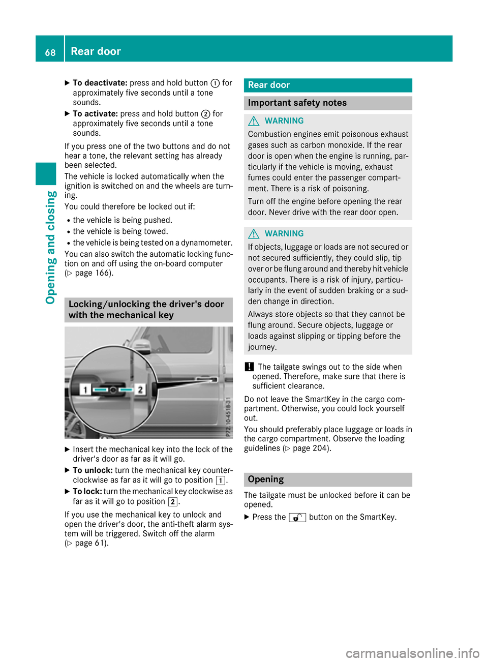
XInsert the mechanical key into the lock of the driver's door as far as it will go.
XTo unlock: turn the mechanical key counter-
clockwise as far as it will go to position 1.
XTo lock:turn the mechanical key clockwise as
far as it will go to position 2.
If yo uusethe mechanical key to unlock and
open the driver's door, the anti-thef talarm sys-
tem will be triggered .Switch off the alarm
(
Ypage 61).
Rear door
Important safety notes
GWARNING
Combustio nengines emi tpoison ouse xhaust
gases such as carbo nmonoxide. If the rear
door is open when the engine is running ,par-
ticularly if the vehicl eismoving, exhaust
fumes could enter the passenger compart-
ment. There is ariskofp oisoning .
Turn off the engine before opening the rear
door. Never drive with the reard ooro pen.
GWARNING
If objects, luggage or load sare not secured or
not secured sufficiently ,they could slip ,tip
overorbef lung around and thereb yhitvehicle
occupants. There is ariskofi njury,p articu-
larly in the event of sudden braking or asud-
de nc hange in direction.
Alway sstoreo bjects so thatt hey cannotbe
flung around .Secure objects, luggage or
load sagain st slipping or tipping before the
journey.
!The tailgate swing soutto the side when
opened. Therefore, make sure thatt hereis
sufficient clearance.
Do not leave the SmartKey in the cargo com-
partment. Otherwise, yo ucould lock yourself
out.
Yo us houl dpreferabl yplace luggage or load sin
the cargo compartment. Observe the loading
guideline s(
Ypage 204).
Opening
The tailgate must be unlockedb efore it can be
opened.
XPress the %button on the SmartKey.
68Rear door
Opening and closing
Page 74 of 286

Opening and closing the sliding sun-
roof
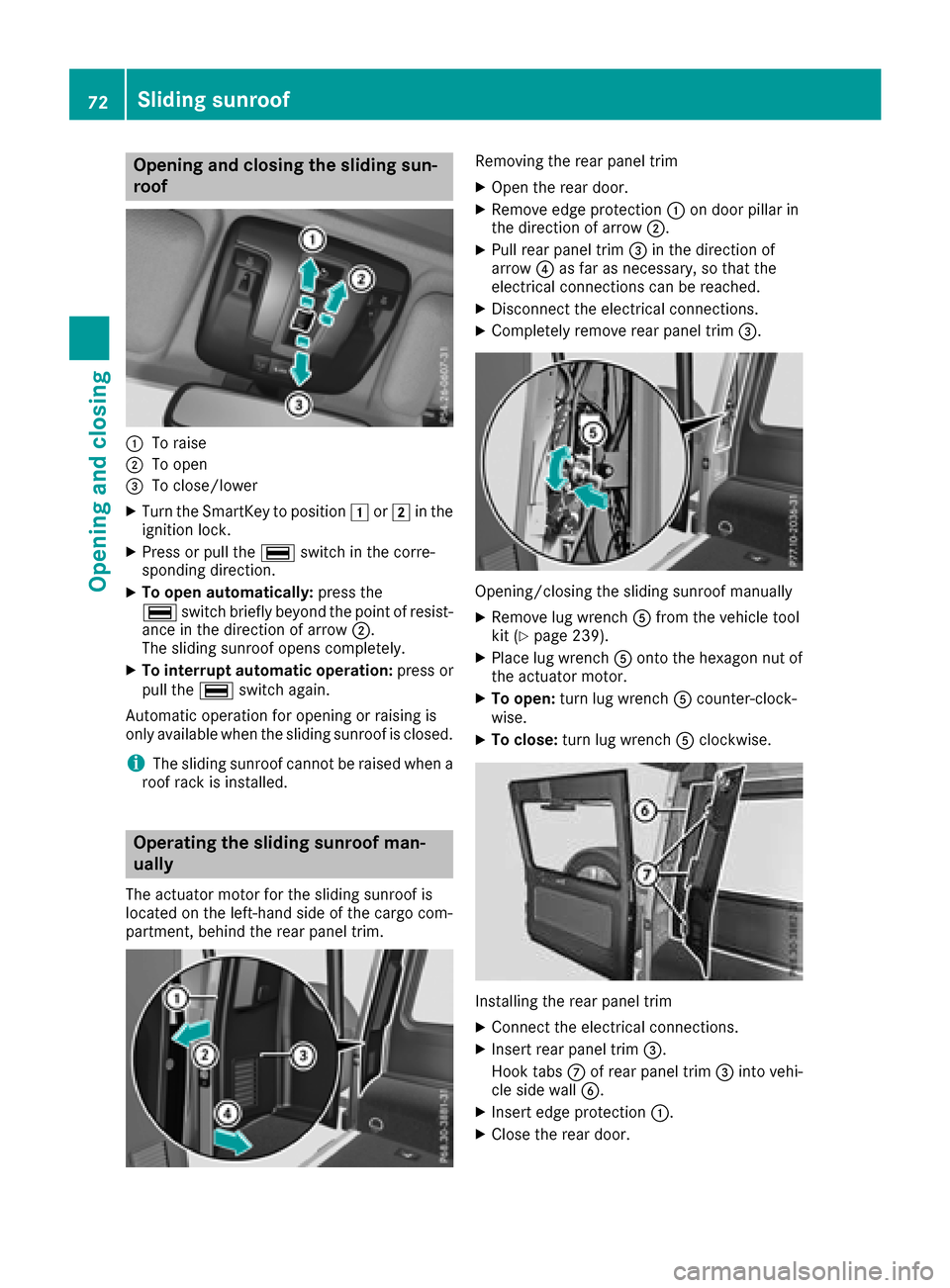
:To raise
;To open
=To close/lower
XTurn the SmartKey to position1or2 in the
ignition lock.
XPress or pull the ¡switch in the corre-
spondin gdirection.
XTo open automatically: press the
¡ switch briefly beyond the point of resist-
ance in the direction of arrow ;.
The sliding sunroof opens completely.
XTo interrupt automatic operation: press or
pull the ¡switch again.
Automatic operation for opening or raising is
only available when the sliding sunroof is closed.
iThe sliding sunroof cannot be raised when a
roof rack is installed.
Operating the sliding sunroof man-
ually
The actuator motor for the sliding sunroof is
located on the left-hand side of the cargo com-
partment, behind the rear panel trim.
Removing the rear panel trim
XOpen the rear door.
XRemove edge protection :on door pillar in
the direction of arrow ;.
XPull rear panel trim=in the direction of
arrow ?as far as necessary, so that the
electrical connections can be reached.
XDisconnect the electrical connections.
XCompletely remove rear panel trim =.
Opening/closing the sliding sunroof manually
XRemove lug wrenchAfrom the vehicle tool
kit (Ypage 239).
XPlace lug wrench Aontothe hexagon nut of
the actuator motor.
XTo open: turn lug wrench Acounter-clock-
wise.
XTo close: turn lug wrench Aclockwise.
Installing the rear panel trim
XConnec tthe electrical connections.
XInser trear panel trim =.
Hook tabs Cof rear panel trim =into vehi-
cle side wall B.
XInsertedge protection :.
XClose the rear door.
72Sliding sunroof
Opening and closing
Page 92 of 286

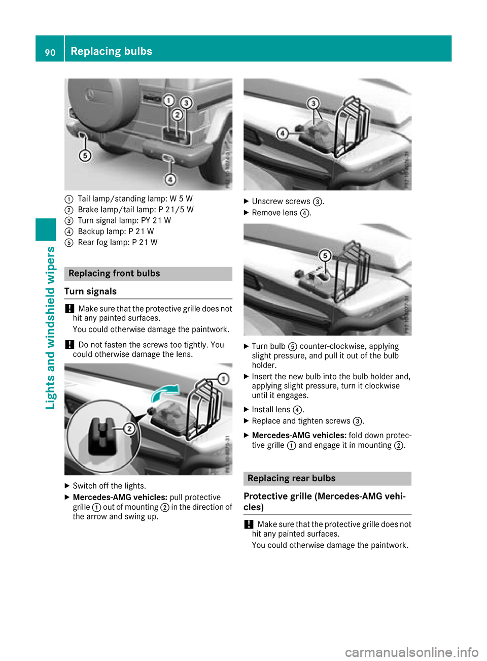
:Tail lamp/standinglamp: W5W
;Brake lamp/tail lamp: P21/5 W
=Turn signal lamp: PY 21 W
?Backup lamp: P21W
ARear fog lamp: P21W
Replacing front bulbs
Turns ignals
!Make sure that the protective grille does not
hit any painted surfaces.
You could otherwise damage the paintwork.
!Do not fasten the screws too tightly. You
could otherwise damage the lens.
XSwitch off the lights.
XMercedes-AMG vehicles: pull protective
grille :out of mounting ;in the direction of
the arrow and swing up.
XUnscrew screws =.
XRemove lens?.
XTurn bulbAcounter-clockwise, applying
slight pressure, and pull it out of the bulb
holder.
XInsert the new bulb into the bulb holder and,
applying slight pressure, turn it clockwise
until it engages.
XInstall lens ?.
XReplace and tighten screws =.
XMercedes-AMG vehicles:fold down protec-
tive grille :and engage it in mounting ;.
Replacing rear bulbs
Protective grille (Mercedes-AMG vehi-
cles)
!Make sure that the protective grille does not
hit any painted surfaces.
You could otherwise damage the paintwork.
90Replacing bulbs
Lights and windshield wipers
Page 93 of 286

Mercedes-AMG vehicles:you must remove
the protective grille before you can replace the
bulbs in the tail lamps.
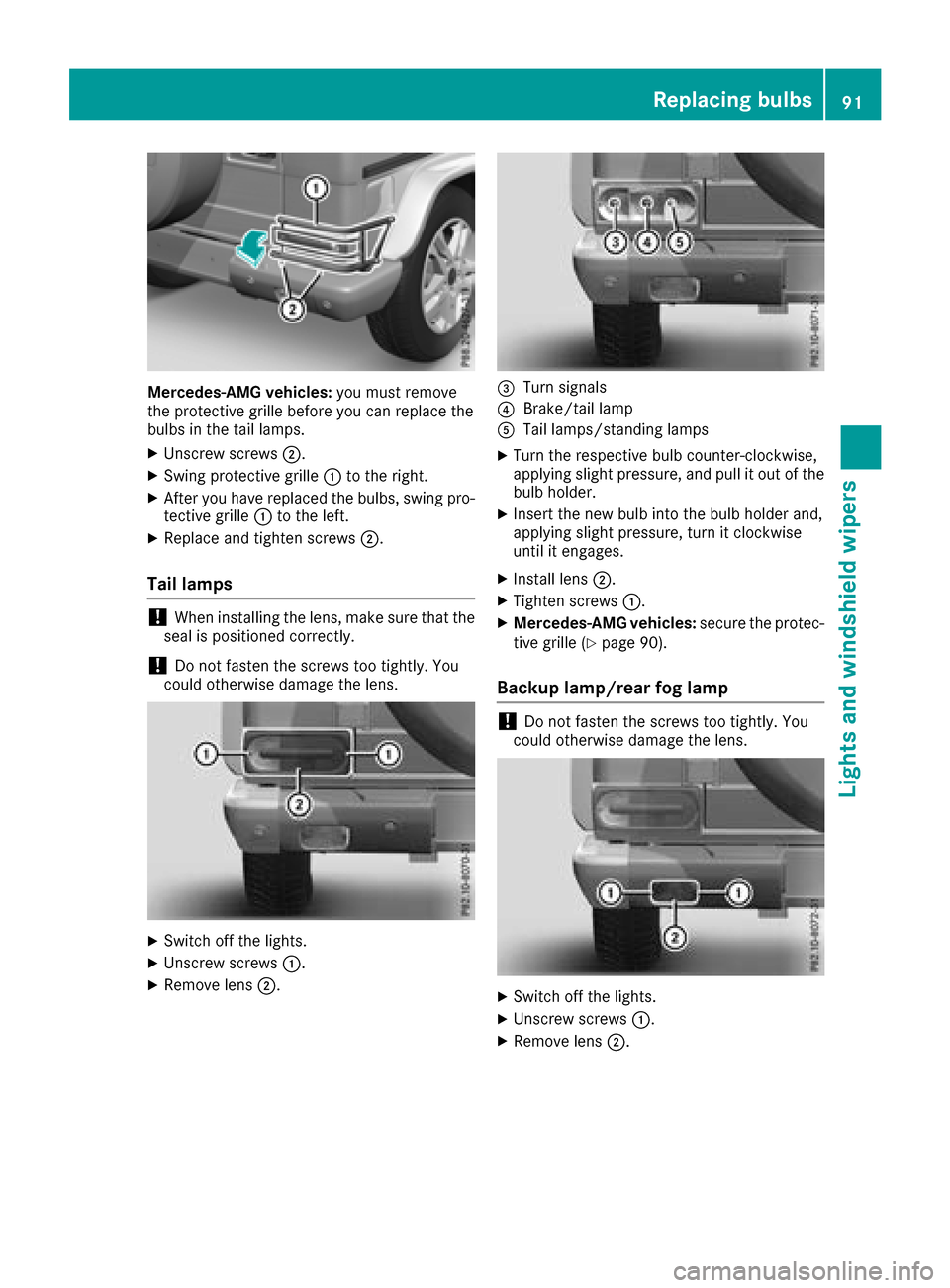
XUnscrew screws ;.
XSwing protective grille :to the right.
XAfter you have replaced the bulbs, swing pro-
tective grille :to the left.
XReplace and tighten screws ;.
Tail lamps
!When installing the lens, make sure that the
seal is positioned correctly.
!Do not fasten the screws too tightly.Y ou
could otherwise damage the lens.
XSwitch off the lights.
XUnscrew screws :.
XRemove lens;.
=Turn signals
?Brake/tail lamp
ATaillamps/standing lamps
XTurn the respective bul bcounter-clockwise,
applying slight pressure, and pul litout of the
bul bh older.
XInsert the new bul binto the bul bholder and,
applying slight pressure, turn it clockwise
until it engages.
XInstall lens ;.
XTighten screws :.
XMercedes-AMG vehicles: secure the protec-
tive grille (Ypag e90).
Backup lamp/rear fog lamp
!Do not fasten the screws too tightly.Y ou
coul dotherwise damage the lens.
XSwitch off the lights.
XUnscrew screws :.
XRemove lens;.
Replacing bulbs91
Lights and windshield wipers
Z
Page 94 of 286

XTurn bulb=counter-clockwise, applying
slight pressure, and pull it out of the bulb
holder.
XInsert the new bulb into the bulb holder and,
applying slight pressure, turn it clockwise
until it engages.
XInstall lens ;.
XTighten screws :.
Windshield wipers
Switching the windshield wipers
on/off
!
Do not operate the windshield wipers when
the windshield is dry, as this could damage
the wiper blades. Moreover, dust that has col-
lected on the windshield/rear window can
scratc hthe glass if wiping takes place when
the windshield/rear window is dry.
If it is necessary to switch on the windshield
wipers in dry weather conditions, alwaysu se
washer fluid when operating the windshield
wipers.
!If the windshield wipers leave smears on the
windshield/rear window after the vehicle has
been washed in an automatic car wash, this
may be due to wax or other residue. Clean the
windshield/rear window with washer fluid
after an automatic car wash.
!Intermittent wiping with rain sensor: due to
optical influences and the windshield becom-
ing dirty in dry weather conditions, the wind-
shield wipers may be activated inadvertently.
This could then damage the windshield wiper
blades or scratc hthe windshield.
For this reason, you should alwayss witch off
the windshield wipers in dry weather.
1$ Windshield wipers off
2ÄIntermittent wipe, normal
3ÅIntermittent wipe, frequent
4°Continuous wipe, slow
5¯Continuous wipe, fast
BíSingle wipe
î Wipes with washer fluid
XSwitch on the ignition.
XTurn the combination switch to the corre-
sponding position.
In the ÄorÅ position, the appropriate
wiping frequency is set automatically according
to the intensity of the rain. In the Åposition,
the rain sensor is more sensitiv ethan in the
Ä position, causing the windshield wiper to
wipe more frequently.
Intermittent wiping is interrupted if you stop the vehicle and open afront door. This protects
people getting into and out of the vehicle from
being sprayed with water.
Intermittent wiping continues when all doors are
closed and:
Ryou shift the automatic transmission to drive
position Dor reverse gear R
or
Ryou change the wiper setting on the combi-
nation switch
92Windshield wipers
Lights and windshield wipers
Page 121 of 286

Opening the fuel filler flap
:To open the fuel filler flap
;Tire pressure table
=Instruction label for fuel type to be refueled
?To insert the fuel filler cap
XSwitchthe engine off.
iWhen the engine is running and the fuel filler
flap is open, the yellow reserve fuel warning
lamp and the =(USA only) or ;(Can-
ada only) Check Engine warning lamp may
light up.
Further information about warning and indi-
cator lamps in the instrument cluster can be
found in the Digital Operator's Manual.
XRemove the SmartKey from the ignition lock.
XTurn the fuel filler cap counterclockwise and
remove it.
XInser tthe fuel filler cap into the holder
bracket on the inside of filler flap ?.
XCompletely insert the filler neck of the fuel
pump nozzle into the tank and refuel.
XOnly fill the tank until the pump nozzle
switches off.
Do not add any more fuel after the pump stops
filling for the first time. Otherwise, fuel may leak
out.
Closing the fuel filler flap
XReplace the cap on the filler neck and turn
clockwise until it engages audibly.
XClose the fuel filler flap.
Close the fuel filler flap before lockin gthe vehi-
cle. If you are driving with the fuel filler cap open, the
8
reservef uel warning lamp flashes. Ames-
sage appears in the multifunction display
(
Ypage 179).
Fuel filler flap emergency release
The emergency release is located in the cargo
compartment ,onthe right-hand side when
viewed in the direction of travel, behind the rear
panel trim.
The vehicle walls in the area around the emer-
genc yrelease have sharp edges. There is arisk
of injury. Avoid contact with the edges on the
inside of the vehicle body.
XOpen the rear door.
XPull off edge protection ;.
XRemove rear wall trim:.
XPull emergency release =in the direction of
the arrow.
The fuel filler flap is unlocked.
XOpen the fuel filler flap (Ypage 119).
Refueling119
Driving and parking
Z
Page 158 of 286

You will findpermissible trailer loads under
"Technical data" (Ypage 284).
Loading atrailer
RWhen loading the trailer, make sure that nei-
the rthe permissible gross trailer weight nor
the permissible gross vehicle weight are
exceeded. The permissible gross vehicle
weight is indicated on the identification plate
on the B-pillar on the driver's side of the vehi-
cle.
You can findt he maximum permissible values
on the type plates of your vehicle and the
trailer. When calculating how much weight
the vehicle and trailer may carry, pay atten-
tion to the respectiv elowest values.
RThe trailer drawbar load on the ball coupling
must be added to the rear axle load to avoid
exceeding the permissible gross axle weight.
The permissible gross vehicle weight is indi-
cated on the identification plate on the B-pil-
lar on the driver's side of the vehicle.
Mercedes-Ben zrecommends atrailer load
where the trailer drawbar noseweight accounts
for 8% to 15% of the permissible gross trailer
weight.
Additional accessories, passengers and load
reduce the permissible trailer load and nose-
weight that your vehicle can tow.
Checking th evehicle and trailer weight
RHave the towin gvehicle, including the driver,
passengers and load, and completely loaded
trailer weighed on asuitable weighing
machine. This will allow you to ensur ethat the
weightsoft he towingvehicle and trailer com-
ply with the maximum permissible values.
RCheck the gross axle weight ratin gofthe front
and rear axles, the gross weight of the trailer
and trailer drawbar load.
Trailer power supply
!
You can connec taccessories with amaxi-
mum power consumption of 180 Wtothe
permanent power supply.
You must not charge atrailer battery using the
power supply.
The trailer socket of your vehicle is equipped at the factory with apermanent power supply. The permanent power supply is supplied via
trailer socket pin 9.
Aq
ualified specialis tworkshop can provide
more information about installing the trailer
electrics.
Trailer with 7-pin connector
Genera lnotes
Trailersw ith 7-pin connector: you can make a
connection to the 13-pin connector on the ball
couplin gusing an adapter plug or, if necessary,
an adapter cable. Bot hcan be obtained in a
qualified specialis tworkshop.
Installing th eadapt er
!Make sure that there is enough slack in the
cable for cornering so that the cable cannot
becom edetached.
XOpen the socket cover.
XInsert the connector with lug :into
groove ;on the socket and turn it clockwise
to the stop.
XMake the cover engage.
XIf you are using an adapter cable, secur ethe
cable to the trailer with cable ties.
When the socket is connected, PARKTRONIC is
deactivated.
156Towing atrailer
Driving and parking
Page 159 of 286

Important safety notes
GWARNING
If you operate information systems and com-
munication equipmen tintegrate dinthevehi-
cle while driving ,you will be distracte dfrom
traffic conditions. You could also lose control
of th evehicle. Ther eisariskofana ccident.
Only operate th eequipmen twhen th etraffic
situation permits. If you are no tsuret hatthis
is possible ,park th evehicl epayin gattention
to traffic condition sand operate th eequip-
men twhen th evehicl eiss tationary.
You must observ ethe legal requirements for th e
country in whic hyou are currentl ydriving when
operating th eon-bo ard computer.
GWARNIN G
If th einstrumen tcluste rhas faile dormal-
functioned, you may no trecognize function
restriction sinsystems relevan ttosafety. The
operating safet yofyour vehicl emay be
impaired .Ther eisar iskofana ccident.
Drive on carefully. Hav ethe vehicl echecked
at aq ualified specialist workshop immedi-
ately.
If th eoperating safet yofyour vehicl eis
impaired ,pull ove rassoonasitiss afetodos o.
Contac taqualified specialist workshop.
The on-board computer only shows message sor
warning sfromc ertai nsystems in th emultifunc-
tion display. You should therefor emakes ure
your vehicl eisoperating safely at all times .
Fo rano verview, see th einstrumen tpanel illus-
tration (
Ypage 32).
Display sand operation
Instrumen tcluster lighting
The brightness control knob is locate donthe
botto mleftoft heinstrumen tcluste r
(
Ypage 32).
XTurn th ebrightness control knob clockwise or
counter-clockwise.
If th eligh tswitch is set to th eÃ, Tor
L position ,the brightness is dependen t
upon th ebrightness of th eambien tlight.
iThe ligh tsensor in th einstrumen tcluste r
automatically control sthe brightness of th e
multifunction display.
In daylight, th edisplays in th einstrumen t
cluste rare no tilluminated.
Speedometer with segments
The segments in th espeedometer indicat e
whic hspee drange is available.
RCruis econtro lactivated (Ypage 131):
The segments ligh tupfromt hestore dspee d
to th eend of th escale.
RDISTRONI CPLUSa ctivated (Ypage 134):
On eort wo segments in th eset spee drange
ligh tup.
RDISTRONI CPLUSd etects avehicl einf ront:
The segments between th espee doft hevehi-
cle in fron tand th estoreds pee dligh tup.
Tachometer
!
Do no tdriveint heoverrevving range, as this
could damag ethe engine.
The red ban dinthetachometer indicates th e
engine's overrevving range.
The fuel suppl yisinterrupted to protect th e
engin ewhen th ered ban disreached.
Outsidet emperatur edisplay
You should pay special attention to road condi-
tion swhen temperatures are aroun dfreezing
point.
Bea rinm indt hatthe outside temperature dis-
play indicates th etem perature measured and
does no trecord th eroad temperature.
The outside temperature display is in th emulti-
function display (
Ypage 159).
Changes in th eoutside temperature are dis-
played after ashort delay.
Display sand operation157
On-boardc omputer and displays
Z