2017 MERCEDES-BENZ G-Class key
[x] Cancel search: keyPage 248 of 286
Towingand tow-starting
Important safety notes
GWARNING
Functions relevant to safety ar erestricted or
no longe ravailable if:
Rthe engine is not running.
Rthe brake system or the powe rsteerin gis
malfunctioning.
Rthere is amalfunctio ninthe voltag esuppl y
or the vehicle's electrical system.
If your vehicl eisbeing towed ,muchm ore
force mayben ecessary to stee rorbrake.
There is ariskofana ccident.
In such cases, us eatow bar. Before towing,
make sure thatt he steeringmoves freely.
GWARNING
Yo uc an no longe rstee rthe vehicl eifthe
steerin gwheel lock hasb eene ngaged .There
is ar iskofana ccident.
Alway sswitch off the ignition when towing the
vehicl ewithat ow cable or atow bar.
GWARNING
When towing or tow-startin ganotherv ehicle
and its weight is greate rthant he permissible
gross weight of your vehicle, the:
Rthe towing ey ecould detach itself
Rthe vehicle/trailer combinatio ncould roll-
over.
There is ariskofana ccident.
When towing or tow-startin ganotherv ehicle,
its weight shoul dnot be greate rthant he per-
missibl egross weight of your vehicle.
Detail sonthe permissibl egross vehicl eweigh t
of your vehicl ecan be found on the vehicl eide n-
tification plate (
Ypage 275).
!When DISTRONICP LUSort he HOLD func-
tio nisa ctivated ,the vehicl ebrakes automat-
icall yinc ertain situations. To avoi
ddamag etothe vehicle, deactivate
DISTRONICP LUSa nd the HOLD functio nin
the following or similar situations:
Rwhen towing the vehicle
Rin the car wash
!The vehicl ecan be towed amaximum of
30 miles (50km). The towing spee dof30mph
(50 km/h )mustn ot be exceeded.
If the vehicl ehasto be towed mor ethan
30 miles (50km), the entire vehicl emustb e
raised and transported.
!Onlys ecurethe tow cable or tow ba rtothe
towing eyes. Yo ucould otherwis edamag ethe
vehicle.
!Do not tow with sling-typ eequipment .This
could damage the vehicle.
!Do not us ethe towing ey efor recovery. This
could damage the vehicle. If in doubt, have
the vehicl erecovered using acrane.
!When towing ,pulla wa yslowly and
smoothly. If the tractiv epower is too high, the
vehicles could be damaged.
!Your vehicles is equipped with an automatic
transmission. Therefore ,you must not have
the vehicl etow-started .The transmission
mayo therwis ebedamaged .
It is better to have the vehicl etransporte dthan
to have it towed away.
If the transferc asec an be shifted into the Neu-
tral position, yo ucan tow away the vehicle.
If the transferc asec anno tbes hifted into the
Neutral position, yo ucan tow away the vehicle
with one axl eraised. Please bear the following in
mind:
Rremove the propeller shaft between the trans-
fer cas eand the rolling axle.
Rturnthe SmartKeytop osition 1in the igni-
tio nlock.
The battery must be connected and charged.
Otherwise, you:
Rcanno tturnt he SmartKeytop osition 2in
the ignition lock
Rcanno tshift the automatic transmission to
position i
Disar mthe automatic locking featur ebefor et he
vehicl eistowed (
Ypage 67).Y oucould other-
wise be locked outw henp ushing or towing the
vehicle.
246Towin gand tow-starting
Breakdow nassistance
Page 249 of 286
Towingeyes
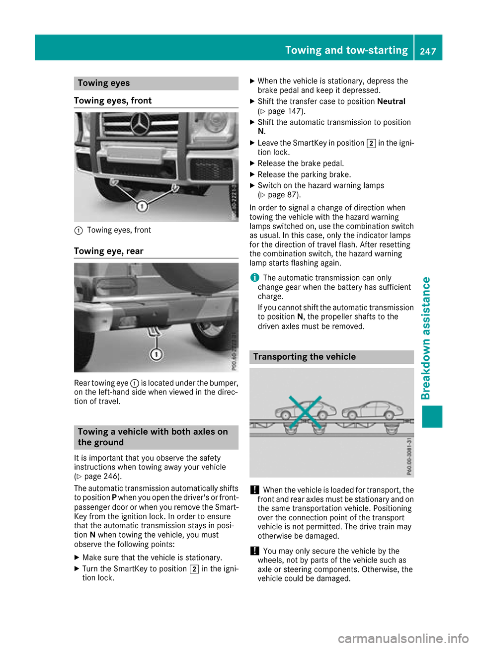
Towin geyes, front
:Towing eyes, front
Towin geye,rear
Rear towing eye :is locate dunder the bumper,
on the left-hand side when viewe dinthe direc-
tio noft ravel.
Towin gavehicle with both axles on
the ground
It is important thaty ouobserve the safety
instructions when towing away your vehicle
(
Ypage 246).
The automatic transmission automaticall yshifts
to position Pwhen yo uopenthe driver's or front-
passenge rdoororw heny ou remove the Smart-
Key fromt he ignition lock. In order to ensure
thatt he automatic transmission stays in posi-
tion Nwhen towing the vehicle, yo umust
observe the following points:
XMake sure thatt he vehicleisstationary.
XTurn the SmartKeytop osition 2in the igni-
tio nlock.
XWhen the vehicl eisstationary, depress the
brake peda land kee pitdepressed.
XShift the transferc asetop osition Neutral
(Ypage 147).
XShift the automatic transmission to position
N.
XLeave the SmartKeyinp osition2in the igni-
tio nlock.
XReleas ethe brake pedal.
XReleas ethe parkin gbrake.
XSwitch on the hazar dwarning lamps
(Ypage 87).
In order to signa lachange of direction when
towing the vehicl ewitht he hazar dwarning
lamps switched on, us ethe combinatio nswitch
as usual. In thisc ase, onlythe indicator lamps
for the direction of travel flash. After res etting
th
e combinatio nswitch ,the hazar dwarning
lamp starts flashing again.
iThe automatic transmission can only
change gear when the battery hass ufficient
charge.
If yo ucanno tshift the automatic transmission
to position N,the propeller shafts to the
driven axles must be removed.
Transporting the vehicle
!When the vehicl eisloade dfor transport, the
front and rea raxles must be stationar yand on
the same transportatio nvehicle. Positioning
ove rthe connectio npoint of the transport
vehicl eisnot permitted .The drive train may
otherwis ebedamaged .
!Youm ayonl ysecur ethe vehicl ebythe
wheels ,not by parts of the vehicl esucha s
axl eors teerin gcomponents. Otherwise, the
vehicl ecould be damaged.
Towin gand tow-starting247
Breakdow nassistance
Z
Page 250 of 286
The towing eyes can be used to pull the vehicle
ontoatrailer or transporter if you wish to trans-
port it.
XTurn the SmartKey to position 2in the igni-
tion lock.
XShift the transfer case to position Neutral
(Ypage 147).
XShift the automatic transmission to position
N .
As soon as the vehicle has been loaded:
XApply the parking brake.
XShift the automatic transmission to posi-
tion P.
XTurn the SmartKey to position uin the igni-
tion lock and remove it.
XSecure the vehicle.
Recovering avehicle thath as become
stuck
!
When recovering avehicle that has become
stuck ,pull it as smoothly and evenly as pos-
sible. Excessive tractive power could damage
the vehicles.
If the drive wheels have become stuck in loose
or muddy ground, pull the vehicle out with
extreme caution, especially so if the vehicle is
loaded.
Never attempt to recover astuck vehicle with a
trailer attached.
Pull out the vehicle backwards, if possible using the track sitmade when it became stuck.
Towing in the event of malfunctions
General notes
!If you are removing the propeller shaft, use
M10 nuts as spacers on the M8 bolts and
secure them with M8 nuts.
New self-locking nuts must be used when the
propeller shafts are refitted.
It is important that you observe the safety
instructions when towing away your vehicle
(
Ypage 246).
iConsult an authorized Mercedes-Benz Cen-
ter.
In the event of damage to the engine,
transmission or electrical system
XShift the transfer case to neutral
(Ypage 147).
XShift the automatic transmission to position
N .
In the event of damage to the transfer
case
Have the propeller shafts between the axles and
the transfer case removed.
In the event of damage to the front axle
Have the propeller shaft between the rear axle
and the transfer case removed.
Then have the vehicle towed away with the front
axle raised.
In the event of damage to the rear axle
Have the propeller shaft between the front axle
and the transfer case removed.
Then have the vehicle towed with the rear axle
raised and wheel rollers under the front axle.
Tow-starting (emergency engine
starting)
!
Vehicles with automatic transmission must
not be tow-started. You could otherwise dam-
age the automatic transmission.
You can find information on "Jump-starting"
under (
Ypage 243).
Fuses
Important safety notes
GWARNING
If you manipulate or bridge afaulty fuse or if
you replace it with afuse with ahigher amper-
age, the electric cables could be overloaded.
This could result in afire. There is arisk of an
accident and injury.
Always replace faulty fuses with the specified
new fuses having the correcta mperage.
248Fuses
Breakdown assistance
Page 251 of 286
The fuses in your vehicle serve to close down
faulty circuits.Ifafuse blows, all the compo-
nentsont he circuit and their functions stop
operating.
Blown fuses must be replaced with fuses of the
same rating, which you can recognize by the
color and value. The fuse ratings are listed in the fuse allocation chart (
Ypage 249).
If an ewly inserted fuse also blows, have the
cause traced and rectified at aqualified special-
ist workshop, e.g. an authorized Mercedes-Benz
Center.
!Only use fuses that have been approved for
Mercedes-Benz vehicles and which have the
correctf use rating for the system concerned.
Otherwise, components or systems could be
damaged.
!Make sure that no moisture can enter the
fuse box when the cover is open.
!When closing the cover, make sure that it is
lying correctly on the fuse box. Moisture seep-
ing in or dirt could otherwise impair the oper-
ation of the fuses.
Before changing afuse
Pay attention to the important safety notes
(Ypage 248).
XSwitch off the engine.
XSwitch off all electrical consumers.
XRemove the SmartKey from the ignition lock.
All indicator lamps in the instrument cluster
must be off.
XSecure the vehicle against rolling away
(Ypage 120).
The fuses are located in various fuse boxes:
RMain fuse box on the driver's side of the dash-
board
RFuse box in the front-passenger footwell
RFuse box in the transmission tunnel
RFuse box in the cargo compartment
The fuse allocation chart and the spare fuses are
in the fuse box on the dashboard on the front-
passenger side (
Ypage 249).
The fuse extractor is in the vehicle tool kit
(
Ypage 120).
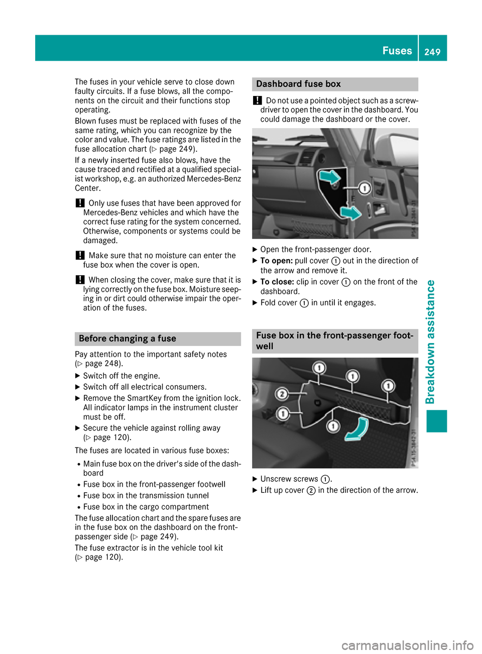
Dashboard fuse box
!
Do not use apointed object such as ascrew-
driver to open the cover in the dashboard. You
could damage the dashboard or the cover.
XOpen the front-passenger door.
XTo open: pull cover :out in the direction of
the arrow and remove it.
XTo close: clip in cover :on the front of the
dashboard.
XFold cover :in until it engages.
Fuse box in the front-passenger foot-
well
XUnscrew screws :.
XLift up cover;in the direction of the arrow.
Fuses249
Breakdown assistance
Z
Page 260 of 286
Your vehicle has also been equipped with a
TPMS malfunction indicator to indicate if the
systemisn ot operating properly. The TPMS
malfunction indicator is combined with the
low tir epressure telltale. When the system
detects amalfunction, the warnin glamp will
flash for approximately aminut eand then
remain continuously illuminated. This
sequence will be repeated every tim ethe vehi-
cle is started as long as the malfunction
exists.
When the malfunction indicator is illuminated,
the syste mmay not be able to detec torsignal
low tir epressure as intended .TPMS malfunc-
tion smay occur for avarietyofr easons,
including the mountin gofincompatible
replacementora lternatetires or wheels on
the vehicle that prevent the TPMS from func-
tioning properly. Always chec kthe TPMS mal-
function telltale afte rreplacing one or more
tires or wheels on your vehicle to ensur ethat
the replacementora lternatetires and wheels
allow the TPMS to continue to function prop-
erly.
It is the driver's responsibility to set the tire
pressure to that recommended for cold tires
which is suitable for the operating situation
(
Ypage 254). Notet hat the correcttirep ressure
for the current operating situation must firstb e
taught-in to the tir epressure monitor .Ifasub-
stantial loss of pressure occurs, the warning
threshold for the warnin gmessageisa ligned to
the taught-in reference values. Restar tthe tire
pressure monitor afte radjusting the pressure of
the cold tires (
Ypage 259). The current pres-
sures are saved as new reference values. As a
result,aw arningmessagew ill appear if the tire
pressure drops significan tly.
The t
ir ep ressure monitor does not warn you of
an incorrectly set tir epressure. Observe the
notes on the recommended tir epressure
(
Ypage 254).
The tir epressure monitor is not able to warn you
of as udden loss of pressure, e.g. if the tir eis
penetrate dbyaforeign object .Inthe eventofa
sudden loss of pressure, bringt he vehicle to a
halt by braking carefully. Avoid abrupt steering
movements.
The tir epressure monitor has ayellow h
warnin glamp on the instrumentc luster for indi-cating
apressure loss or malfunction. The way
that the warnin glamp flashes or lightsupi ndi-
cates whether atirep ressure is too low or
whether the tir epressure monitor is malfunc-
tioning:
Rif the h warnin glamp is lit continuously,
the tir epressure in one or more tires is sig-
nificantly too low. The tir epressure monitor is
not malfunctioning.
Rif the h warnin glamp flashes for around a
minut eand the nremainsl it constantly, the
tir ep ressure monitor is malfunctioning.
In addition to the hwarnin glamp, amessage
appears in the multifunction display. Observe
the information on display messages
(
Ypage 183).
It may tak euptoten minutes for amalfunction
of the tir epressure monitor to be indicated. The
malfunction is indicated firstbyt heh tire
pressure warnin glamp flashingf or approx-
imately one minut eand the nremaining lit. If the
malfunction has been rectified, the htire
pressure warnin glamp goes out afte rdrivingf or
af ew minutes.
The tir epressure values indicated by the on-
board computer may differf rom those meas-
ured at agas st
ation with apressure gauge. The
tir ep ressures shown by the on-board computer
refertot hose measured at sea level. At high
altitudes, the tir epressure values indicated by a
pressure gauge are higher than those shown by
the on-board computer .Inthis case, do not
reduce the tir epressures.
The operation of the tir epressure monitor can
be affected by interference from radio transmit-
tin ge quipment( e.g. radio headphones, two-way
radios) that may be being operated in or near the
vehicle.
Checking th etirep ressuree lectroni-
cally
XMake sure that the SmartKey is in position 2
in the ignition lock.
XPress the =or; button on the steering
wheel to selectt heServ.menu.
XPress the 9or: button to select
Tire Pressure.
XPress the abutton.
The multifunction display shows the current
tir ep ressure of each wheel.
If the vehicle has been parked for over
20 minutes, the Tire pressure will be
258Tirep ressure
Wheels and tires
Page 261 of 286

displayed after drivingafew minutesmessage appears.
After ateach-in process, the tire pressure mon-
itor automaticallyd etects new wheels or new
sensors. As long as aclear allocation of the tire
pressure value to the individual wheels is not
possible,t heTire
PressureMonitorActivedisplaym essage is shown instead of the tire
pressure display. The tire pressures are already
being monitored.
If as pare wheel is mounted, the system may
continue to show the tire pressure of the wheel
that has been removed for afew minutes. If this
occurs, note that the value displayed for the
position where the spare wheel is installed is not
the same as the current tire pressure of the
spare wheel.
Tire pressure monitor warning mes-
sages
If the tire pressure monitor detects apressure
loss in one or more tires, awarning message is
shown in the multifunction display. The yellow
h tire pressure warning lamp then lights up.
RIf the Correct Tire Pressuremessage
appears in the multifunction display, the tire
pressure in at least one tire is too low. The tire
pressure must be corrected at the next oppor-
tunity.
RIf the Check Tiresmessage appears in the
multifunction display, the tire pressure in at
least one tire has dropped significantly. The
tires must be checked.
RIf the Caution -Tire Malfunc.message
appears in the multifunction display, the tire
pressure in at least one tire has dropped sud-
denly. The tires must be checked.
Be sure to observe the instructionsa nd safety
notes in the displaym essages in the "Tires" sec-
tion (
Ypage 183).
If the wheel positions on the vehicle are rotated, the tire pressures may be displayed for the
wrong positions for ashort time. This is rectified
after afew minutes of driving, and the tire pres-
sures are displayed for the correct positions.
Restarting the tire pressure monitor
When you restart the tire pressure monitor, all
existing warning messages are deleted and the
h warning lamp goes out. The monitor uses
the currently set tire pressures as the reference
valuesf or monitoring. In most cases, the tire pressure monitor will automaticallyd
etect the
new reference valuesa fter you have changed
the tire pressure. However, you can also set ref-
erence valuesm anuallyasdescribed here. The
tire pressure monitor then monitors the new tire
pressure values.
XSet the tire pressure to the value recommen-
ded for the corresponding driving situation on
the Tire and Loading Information placard on
the B-pillar on the driver's side.
You can find more tire pressures for various
operating conditions in the tire pressure table
inside the filler flap.
Observe the information on tire pressure
when doing so (
Ypage 254).
XMake sure that the tire pressure is correct on
all four wheels.
XMake sure that the SmartKey is in position 2
in the ignition lock.
XPress the =or; button on the steering
wheel to select the Serv.menu.
XPress the9or: button to select
Tire Pressure.
XPress the abutton.
The multifunction displays hows the current
tire pressure for each tire or the Tire pres‐
surewillbedisplayedafterdrivingafew minutesmessage appears.
XPress the :button.
The UseCurrentPressuresasNewRef‐erenceValuesmessage appears in the mul-
tifunction display.
If you wish to confirm the restart:
XPress the abutton.
The TirePress.MonitorRestartedmes-
sage appears in the multifunction display.
After driving for afew minutes, the system
checks whether the current tire pressures are within the specified range. The new tire pres-
sures are then accepted as reference values
and monitored.
If you wish to cancelt he restart:
XPress the%button.
The tire pressure valuess tored at the last
restart will continue to be monitored.
Tire pressure259
Wheels and tires
Z