2017 MERCEDES-BENZ E43AMG coolant
[x] Cancel search: coolantPage 11 of 482

1Speedom eter →
199
2 ÷ ESP
®
3
#! Turn signal light →
113
4 Ð Steering assis tance malfunction
5 Multifunction displ ay →
202
6 ! ABS malfunction
7 ; CheckEngine
8 Tach ome ter →
199
9 % This indicator lamp has no function
A Elect ric park ing brake applied (red)
F USA only
! Canada only
B Brakes (red)
$ USA only
J Canada only
C # Electrical malfunction
D
· Distance warning
E ? Coolant too hot/cold
F Coolant temp erature gauge →
199
G J Brakes (yell ow)
H ! Electric pa rking brake (yellow)
I 6 Restra int sy stem →
31
J ü Seat belt is not fastened
K T Parking lights →
112
L Fuel le vel indicator
8 Fuelreser vewith fuel filler cap location
indicator
M K High beam →
113
N L Low beam →
112
O R Rear fog light →
113
P h Tire pressure monitoring sy stem
Q å ESP
®OFF
Ataglance – Warning and indicator lamps 9
Page 13 of 482

1Speedom eter →
199
2 ü Seat belt is not fastened
3 #! Turn signal light →
113
4 Multifunction display →
202
5 Tach ome ter →
199
6 å ESP
®OFF
÷ ESP
®
7
K High beam →
113
L Low beam →
112
T Parking lights →
112
8 ? Coolant too hot/cold
9 Coolant temp erature gauge →
199
A · Distance warning
B Ð Steering assis tance malfunction
C # Electrical malfunction
D Brakes (red)
$ USA only
J Canada only
E Fuel le vel indicator
F 8 Fuelreser vewith fuel filler cap location
indicator
G R Rear fog light →
113
H 6 Restra int sy stem →
31
I % This indicator lamp has no function
J ; Check Engine
K J Brakes (yellow)
L Elect ric park ing brake applied (red)
F USA only
! Canada only
M h Tire pressure monitoring sy stem
N ! ABS malfunction
O ! Electric park ing brake (yellow)
Ataglance – Warning and indicator lamps 11
Page 201 of 482
Instrument Displayoverview
&
WARNING Risk of accident due toan
instrument display malfunction
If th e instrument display has failed or mal‐
functioned, you cannot recognize function
re strictions applying tosaf etyre leva nt sys‐
te ms.
The operating saf etyof your vehicle may be
impaired.
#Drive on carefull y.
#Have theve hicle checked immediately
at a qualified specialist workshop.
Ifth e operating saf etyof your vehicle is
impaired, park theve hicle safely as soon as pos‐
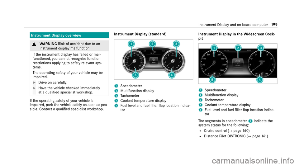
sible. Contact a qualified specialist workshop. Instrument Display (standard)
1Speedome
ter
2Multifunction display
3Ta ch ome ter
4Coolant temp erature display
5Fuel le vel and fuel filler flap location indica‐
to r Instrument Display in
theWi descreen Co ck‐
pit
1Speedom eter
2Multifunction display
3Ta ch ome ter
4Coolant temp erature display
5Fuel le vel and fuel filler flap location indica‐
to r
The segments in speedome ter1 indica tethe
sy stem status forth efo llowing:
RCruise control (→page 160)
RDis tance Pilot DISTRONIC (→pa ge 161)
Instrument Display and on-board computer 19
9
Page 202 of 482
Vehicles with Traf fic Sign Assist and Wide‐
scre en Cockpit: detected instructions and traf‐
fi c signs appear in the speedome ter
(
→page 191).
* NO
TEEngine damage duetoexc essively
high engine speeds
The engine will be damaged if youdriv ewit h
th e engine in theov errevving range.
#Do not drive wi th the engine in theove r‐
re vving range.
The fuel supply is inter rupted toprotect the
engine when there d band in tach ome ter3
(o ve rrev ving range) is reached.
During no rmal operating conditions, coolant
te mp erature display 4may rise to248 °F
(120 °C).
& WARNING Danger of burn s when open‐
ing the hood
If yo u open the hood when the engine has
ove rheated or during a fire inthe engine
compartment, you could come into contact
wit h hot gases or other escaping operating
fl uids.
#Before opening the hood, allow the
engine tocool down.
#Intheeve nt of a fire inthe engine com‐
partment, keep the hood closed and
call thefire service.
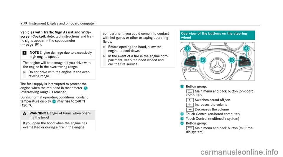
Overview of the butto ns onthest eering
wheel
1But ton group:
% Main menu and ba ckbutton (on-board
computer)
8 Switches sound off/on
W Increases thevo lume
X Decreases thevo lume
2Touch Control (on-board co mputer)
3Touch Control (multimedia sy stem)
4Button group:
% Main menu and back button (multime‐
dia sy stem)
200
Instrument Display and on-board computer
Page 310 of 482
#Make surethat no engine oil is spilled
next tothefiller opening.
#Allow the engine tocool off and thor‐
oughly clean the engine oil from compo‐
nent parts before starting theve hicle.
* NO
TEEngine damage causedbyan
incor rect oil filter, incor rect oil or addi‐
tives
#Do not use engine oils or oil filters
which do not cor respond tothe specifi‐
cations explicitly prescribed forth e
service inter vals.
#Do not alter the engine oil or oil filter in
order toachie velonger change inter vals
th an prescri bed.
#Do not use additives.
#Follow the instructions in the service
inter val display rega rding the oil
ch ange.
* NO
TEDama gecaused bytopping up too
much engine oil
To pping up too much engine oil can cause
damage tothe engine or the catalytic con‐
ve rter.
#Ha ve excess engine oil siphoned off at
a qu alified specialist workshop.
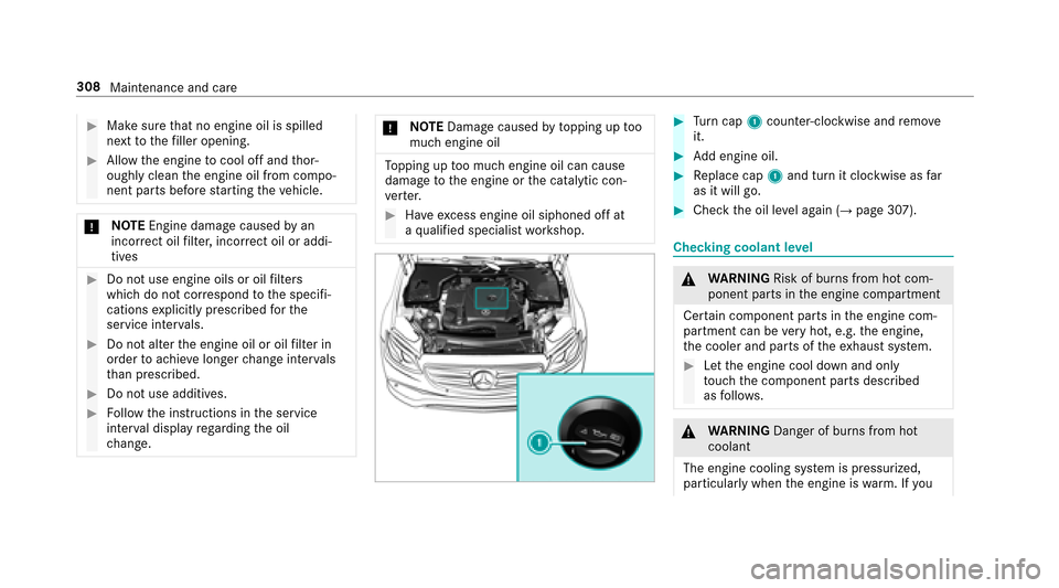
#Tu rn cap 1counter-clockwise and remo ve
it.
#Ad d engine oil.
#Replace cap 1and turn it clockwise as far
as it will go.
#Check the oil le vel again (→page 307).
Checking coolant le vel
&
WARNING Risk of burn s from hot com‐
ponent parts in the engine compartment
Cer tain component parts in the engine com‐
partment can be very hot, e.g. the engine,
th e cooler and parts of theex haust sy stem.
#Let the engine cool down and only
to uch the component parts described
as follo ws .
&
WARNING Danger of burn s from hot
coolant
The engine cooling sy stem is pressurized,
particularly when the engine is warm. If you
308
Maintenance and care
Page 311 of 482
openthe cap, you could bescalded byhot
coolant spr aying out.
#Let the mo tor cool down before opening
th e cap.
#When opening the cap, wearglove s and
pr otective eyew ear.
#Slowly turn the cap half a turn toallow
pressure toescape.
#Park theve hicle on a flat sur face.
#Check the coolant temp erature display in the
instrument clus ter.
The coolant temp erature must be below
15 8 °F (70 °C).
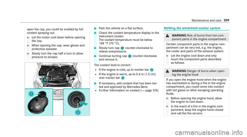
#Slowly turn cap 1counter-clockwise to
re lie ve ove rpressure.
#Continue turning cap 1counter-clockwise
and remo veit.
The coolant le vel is cor rect:
RIfth e engine is cold, up tomar ker bar 2
RIfth e engine is warm, up to0.6 in (1.5 cm)
ove r mar ker bar 2
#If necessar y,add coolant that has been tes‐
te d and appr ovedby Mercedes-Benz.
RFurther information on coolant (→page 376)
Re filling the windshield washer sy stem
&
WARNING Risk of burn s from hot com‐
ponent parts in the engine compartment
Cer tain component parts in the engine com‐
partment can be very hot, e.g. the engine,
th e cooler and parts of theex haust sy stem.
#Let the engine cool down and only
to uch the component parts described
as follo ws .
&
WARNING Danger of burn s when open‐
ing the engine hood
If yo u open the engine hood when the engine
has overheated or during a fire inthe engine
compartment, you could come into contact
wit h hot gases or other escaping operating
fl uids.
#Before opening the engine hood, allow
th e engine tocool down.
#Intheeve nt of a fire inthe engine com‐
partment, keep the engine hood closed
and call thefire service.
Maintenance and care 309
Page 314 of 482
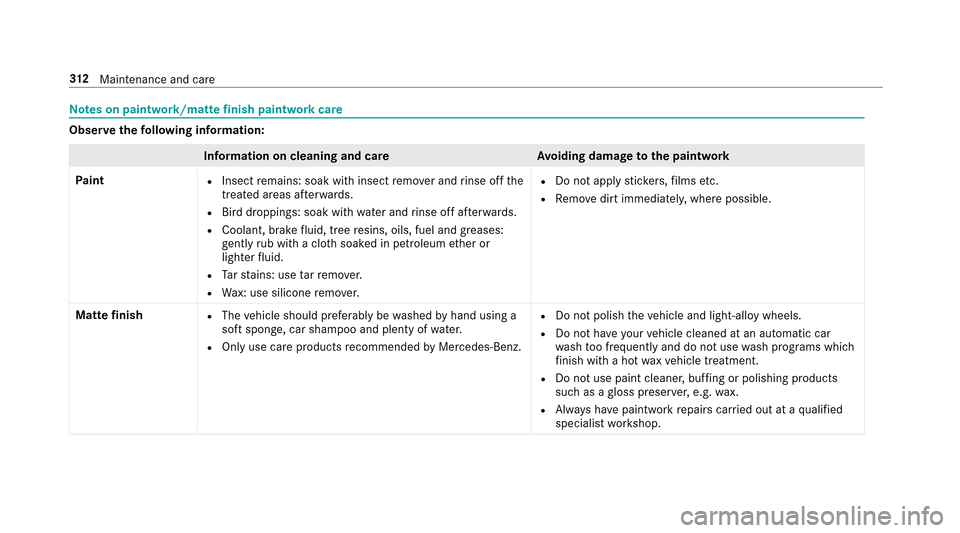
Notes on paintwo rk/matte finish paintwo rkcare
Obser vethefo llowing information:
Information on cleaning and car eAvoiding damage tothe paintwork
Pa int
RInsect remains: soak with insect remo ver and rinse off the
trea ted areas af terw ards.
RBird droppings: soak with water and rinse off af terw ards.
RCoolant, brake fluid, tree resins, oils, fuel and greases:
ge ntly rub with a clo thsoaked in petroleum ether or
lighter fluid.
RTa rst ains: use tarre mo ver.
RWa x: use silicone remo ver.
RDo not apply sticke rs,fi lms etc.
RRe mo vedirt immediately, where possible.
Matte finish
RThe vehicle should preferably be washed byhand using a
soft sponge, car shampoo and plenty of water.
ROnly use care products recommended byMercedes-Benz.
RDo not polish theve hicle and light-alloy wheels.
RDo not ha veyour vehicle cleaned at an automatic car
wa sh too frequently and do not use wash programs which
fi nish wi tha hot waxve hicle treatment.
RDo not use paint cleaner, buf fing or polishing products
such as agloss preser ver,e.g. wax.
RAlw ays ha vepaintwork repairs car ried out at a qualified
specialist workshop.
31 2
Maintenance and care
Page 358 of 482
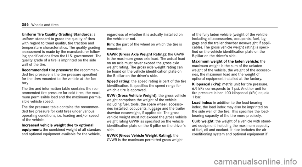
Uniform Tire Quality Grading Standards: a
uniform standard tograde thequ ality of tires
with rega rd totread quality, tire traction and
te mp erature characteristics. The quality grading
assessment is made bythe manufacturer follow‐
ing specifications from theU. S. go vernment. The
qu ality grade of a tire is imprinted on the side
wa ll of the tire.
Re commended tire pressure :th ere commen‐
ded tire pressure is the tire pressure specified
fo rth e tires mounted totheve hicle at thefa c‐
to ry.
The tire and information table conta insthere c‐
ommended tire pressure for cold tires, the maxi‐
mum permissible load and the maximum permis‐
sible vehicle speed.
The tire pressure table conta insthere commen‐
ded tire pressure for cold tires under various
operating conditions, i.e. loading and/or speed
of theve hicle.
Increased vehicle weight due tooptional
equipment: the combined weight of all standard
and optional equipment available forth eve hicle, re
ga rdless of whe ther it is actually ins talled on
th eve hicle or not.
Rim: the part of the wheel on which the tire is
mounted.
GA WR (Gross Axle Weight Rating): the GAWR
is the maximum gross axle load. The actual load
on an axle must ne verexc eed the gross axle
we ight rating. The gross axl e
we ight rati
ng can
be found on theve hicle identification plate on
th e B‑pillar on the driver's side.
Speed rating: the speed rating is pa rtof the tire
identification. It specifies the speed range for
which a tire is appr oved.
GV W (Gross Vehicle Weight): the gross vehicle
we ight comprises thewe ight of theve hicle
including fuel, tools, the spare wheel, accesso‐
ri es ins talled, occupants, luggage and the trailer
dr aw bar nose weight, if applicable. The gross
ve hicle weight must not exceed the gross vehicle
we ight rating GVWR as specified on theve hicle
identification plate on the B‑pillar on the driver's
side.
GV WR (Gross Vehicle Weight Rating): the
GV WR is the maximum permitted gross weight of
the fully laden vehicle (weight of theve hicle
including all accessories, occupants, fuel, lug‐
ga ge and the trailer dr awbar nose weight if appli‐
cable). The gross vehicle weight rating is speci‐
fi ed on theve hicle identification plate on the
B‑pillar on the driver's side.
Maximum weight of the laden vehicle: the
maximum weight is the sum of the unladen
we ight of theve hicle, thewe ight of the accesso‐
ri es, the maximum load and thewe ight of
optional equipment ins talled at thefa ctor y.
Kilopascal (kPa): metricunit for tire pressure .
6.9 kPa cor responds to1 psi. Ano ther unit for
tire pressure is bar.100 kilop ascal (kPa
) equals
1 bar.
Load index: in additiontothe load-bearing
index, the load index may also be imprinted on
th e side wall of the tire. This specifies the load-
bearing capacity of the tire more precisel y.
Curb weight: thewe ight of a vehicle with stand‐
ard equipment including the maximum capacity
of fuel, oil and coolant. It also includes the air
conditioning sy stem and optional equipment if
356
Wheels and tires