Page 14 of 585
1
Speedom eter →
261
2 ÷ ESP®
→
524
3 #! Turn signal light →
13 6
4 Ð Steering assis tance malfunction →
533
5 Multifunctio ndispl ay →
264
6 ! ABS malfunction →
524
7 ; Engine diagnosis →
535
8 Revc ounter →
261
9 % Diesel engine: preglow
A ! Electric parking brak eapplied( red) →
524
B J Brakes (red) →
524
C # Electrical fault →
535
D · Distance warning →
531
E ? Coolant tooh ot/cold →
535
F Coolant temp eratur edisplay →
261
G J Brakes (yellow) →
524 H
! Electricp arkin gb rake (yellow) →
524
I 6 Restra int sy stem →
32
J ü Seat belt is no tfas tened →
530
K j Trailer hit chis no toperational or is swivel‐
ling →
533
L T Standing lights →
13 4
M Fuel le veld isplay
8 Fuelreser vewit hfuel filler flap location
indicator →
535
N K Main beam →
13 6
O L Dippe dbeam →
13 4
P R Rear fogl ight →
13 5
Q AIR BOD YCONTROL/DYNAMIC BODY CONTROL
malfunctioning →
531
R h Tyre pressur emonitoring sy stem →
538
S å ESP®
OFF →
524 At
ag lanc e–O verviewofw arning and indicator lamps 11
Page 16 of 585
1
Speedom eter →
261
2 AIR BODY CONTROL/DYNAMIC BODY CONTROL
malfunctioning →
531
3 #! Turn signal light →
13 6
4 Multifunction display →
264
5 Revc ounter →
261
6 å ESP®
OFF →
524
÷ ESP®
→
524
7 K Mainb eam →
13 6
L Dippe dbeam →
13 4
T Standing lights →
13 4
8 ? Coolan ttoo hot/cold →
535
9 Coolant temp eratur edisplay →
261
A · Distance warning →
531
B Ð Steering assis tance malfunction →
533
C # Electrica lfault →
535 D
J Brakes (red) →
524
E ü Seat belt is no tfas tened →
530
F Fuel le veld isplay
G 8 Fuelreser vewit hfuel filler flap location
indicator →
535
H R Rear fogl ight →
13 5
I 6 Restra int sy stem →
32
J % Diesel engine: preglow
K ; Engine diagnosis →
535
L J Brakes (yellow) →
524
M ! Electricp arkin gb rake applied (red) →
524
N h Tyre pressur emonitoring sy stem →
538
O ! ABS malfunction →
524
P ! Electricp arkin gb rake (yellow) →
524
Q j Trailer hit chis no toperational or is swivel‐
ling →
533 At
ag lanc e–O verviewofw arning and indicator lamps 13
Page 77 of 585
Problem
Possible causes/consequences and M
MSolutions
R The keyisf aulty. #
Activat eKEYLESS-G O. #
Chec kthe batter yusing theb atter ychec klam pand replace if necessar y. #
Use thee mer gency keytol ockoru nlockthe vehicle . #
Have thev ehicle and keyc hec kedataq ualified specialis tworks hop. Ac
tivating/deactivatin gthe automati cloc k‐
ing feature The
vehicle is loc keda utomatically when the
ignition is switched on and thew heels ar eturn‐
ing fast erthan walkin gpace. #
Toactivate: press and hold button 2for
appr oximatel yfives econds until an acoustic
signal sounds. #
Todeactivate: press and hol dbutton 1for
appr oximatel yfives econds until an acoustic
signal sounds.
Ther eisad anger of being loc kedo ut if thef unc‐
tion is activated:
R While thev ehicle is being tows tarted/
pushed.
R Onaroller dynamome ter. 74
Opening and closing
Page 139 of 585

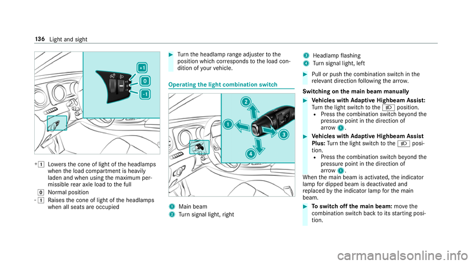
+1
Lowe rsthec oneofl ight of theh eadlamps
when thel oad compartmen tisheavily
laden and when using them aximum per‐
missible rear axle load tothef ull
g Normal position
- 1
Raises thec oneofl ight of theh eadlamps
when all seats ar eoccupied #
Turn theh eadlam prang eadjus tertot he
position whic hcorresponds tothel oad con‐
dition of your vehicle. Operating
thel ight combination switch 1
Main beam
2 Turn signal light, right 3
Headlam pflashing
4 Turn signal light, left #
Pull or push thec ombination switc hinthe
re leva nt di rection following thea rrow.
Switching on them ainb eam manually #
Vehicles with Adaptiv eHighbeam Assis t:
Tu rn thel ight switc htotheL position.
R Press thec ombination switc hbeyond the
pressur epoint in thed irection of
ar row 1. #
Vehicles with Adaptiv eHighbeam Assist
Plus: Turn thel ight switc htotheL posi‐
tion. R Press thec ombination switc hbeyo ndthe
pressur epoint in thed irection of
ar row 1.
When them ain beam is activated, thei ndicator
lam pfor dipped beam is deactivated and
re placed bythei ndicator lam pfor them ain
beam. #
Toswitc hoffthem ainb eam: movethe
combination switc hbacktoi tsstartin gposi‐
tion. 13 6
Light and sight
Page 147 of 585

Ac
tivatin gclimate-dependen tlighting #
Select Climate. #
Activate Oor deacti vate ª thef unction.
The colour of thea mbient lighting adapts to
suit thea ir conditionin gsetting.
Ac tivatin gwelcome lighting #
Select Welcome. #
Activate Oor deacti vate ª thef unction.
When thev ehicle is unloc ked, as pecial inte‐
ri or lighting sequence runs. Settin
gthe in terior lighting switch-of fdelay
time Multimedia sy
stem:
, Vehicle .
÷ Light settings .
Inte-
rior light shut-off #
Setthe switch-of fdela ytime. Changing bulbs (onl
yfor vehicles with halo‐
ge nh eadla mps) Note
sonc hanging bulbs &
WARNING Risk of bu rnsf romh otcom‐
ponent parts whils treplacing abulb
Bulbs, lamps and plugs can become very hot
during operation.
When replacing abulb, youc ould bur nyour‐
self on these componen tparts. #
Allo wthe component parts tocool
down befor ereplacing theb ulb. R
Do no tuse ab ulb if it has been dropped or if
its glass has been sc ratched. The bulb may
ot herwise explode.
R Do no ttouc hthe glass bulb wit hyour bare
hands.
R Protect bulbs from moistur eand do no tallow
bulbs tocome int ocontact wi thliquids. Overvie
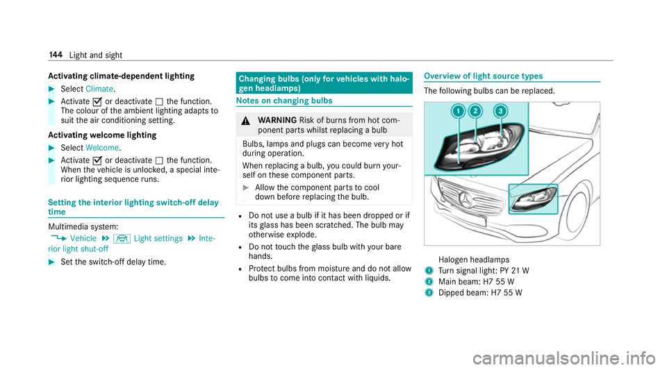
woflight source types The
following bulbs can be replaced. Halogen headlamps
1 Turn signal light :PY21W
2 Main beam: H7 55 W
3 Dipped beam: H7 55 W 14 4
Light and sight
Page 148 of 585

Changing
thef ront bulbs (vehicles wit hhalo‐
ge nh eadla mps) Fi
tting/ removing the co vero nthe front
whee larch
Re quirements:
R The lightin gsystemiss witched off.
R The appropriat efront wheel is turned
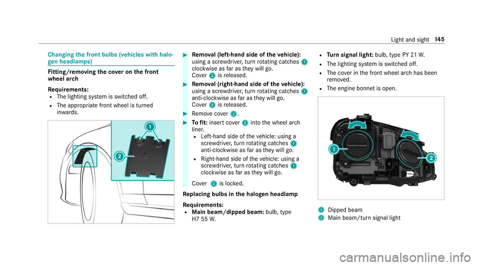
in wa rds. #
Remo val(left-hand side of thev ehicle):
using ascrew driver ,tur nr otating catches 1
clockwise as farast heyw ill go.
Co ver 2isreleased. #
Remo val(right-hand side of thev ehicle):
using ascrew driver ,tur nr otating catches 1
anti-clockwise as farast heyw ill go.
Co ver 2isreleased. #
Remo vecover 2. #
Tofit: inse rtco ver 2intot he wheel ar ch
liner.
R Left-hand side of thev ehicle: using a
scr ewdriver ,tur nr otating catches 1
anti-clockwise as farast heyw ill go.
R Right-han dside of thev ehicle: using a
scr ewdriver ,tur nr otating catches 1
clockwise as farast heyw ill go.
Co ver 2is loc ked.
Re placing bulbs in the halo genh eadla mp
Requ irements:
R Main beam/dipped beam: bulb, type
H7 55 W. R
Turn signal light: bulb, type PY 21W.
R The lighting sy stem is switched off.
R The co verint he front wheel ar chhas been
re mo ved.
R The engin ebonn etis open. 1
Dipped beam
2 Main beam/tur nsignal light Light and sight
14 5
Page 149 of 585
#
Turn ther ele vant housing co vera nti-clock‐
wise and remo veit. #
Main beam/dipped beam: turnthe soc ket
anti-clockwis eand remo veit. #
Turn signal light: turnthe soc keta nti-clo ck‐
wise, unloc kand remo veit. #
Pull theb ulb out of thes ocket. #
Inse rtthen ew bulb int othe soc ketsot hat
th ee ntir ebase of theb ulb is resting on the
bottom of thes ocket. #
Inse rtsoc keta nd tur nitclock wise. #
Press on theh ousing co vera nd tur nitclock‐
wise. #
Replace thec over in thef ront wheel ar ch. Wi
ndscreen wiper sand windscreen washer
sy stem Switching
thew indscreen wiper son/off 1
gWindsc reen wiper soff
2 Ä Intermittent wiping, normal
3 Å Intermittent wiping, frequent 4
° Continuous wiping, slow
5 ¯ Continuous wiping, fast #
Turn thec ombination switc htothe cor rect
position 1-5. #
Singlew ipe /washing: pushtheb utton on
th ec ombination switc hinthe direction of
ar row 1.
R í Single wipe
R î Wiping wit hwashe rfluid 14 6
Light and sight
Page 260 of 585

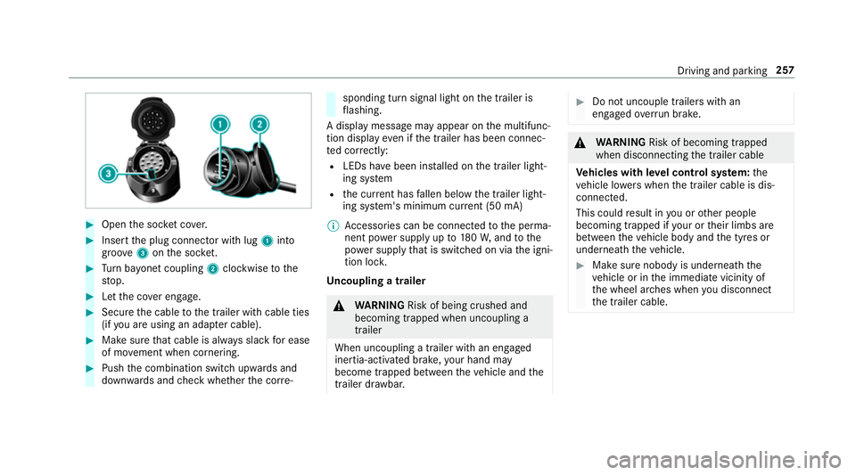
#
Open thes ocketc ove r. #
Inser tthe plug connector wit hlug 1 into
groo ve3 onthes ocket. #
Turn bayone tc oupling 2clockwise tothe
st op. #
Letthe co vere ngage. #
Secur ethe cable tothet railer wit hcable ties
(if youa reusin gana dapterc able). #
Mak esuret hat cabl eisalway ss lac kfor ease
of mo vement when cornering. #
Push thec ombination switc hupwards and
down wardsa nd checkw hether thec orre‐ sponding tur
nsignal light on thet railer is
fl ashing.
Ad ispla ymessag emayappear on them ultifunc‐
tion displa yevenift he trailer has been connec‐
te dc orrectly:
R LEDs ha vebeen ins talled on thet railer light‐
ing sy stem
R thec urrent ha sfallen belo wthe trailer light‐
ing sy stem's minimum cur rent (50 mA)
% Accessorie scan be connected tothep erma‐
nentp owersupp lyup to180W,a ndtothe
po we rsupp lythat is swit ched on via thei gni‐
tion loc k.
Un coupling atrailer &
WARNING Risk of being crushed and
becoming trapped whe nuncoupling a
trailer
Whe nuncoupling atrailer with an engaged
ine rtia-activated brake, your han dmay
become trapped between thev ehicle and the
traile rdrawbar. #
Do no tuncouple trailer swithan
engaged overrunb rake. &
WARNING Risk of becoming trapped
whe ndisconnecting thet railer cable
Ve hicles with le velc ontrol sy stem: the
ve hicle lo werswhen thet railer cable is dis‐
connected.
This could result in youoro ther people
becoming trapped if your or their limbs are
between thev ehicle body and thet yres or
underneat hthe vehicle. #
Mak esuren obody is underneat hthe
ve hicle or in thei mmediat evicinity of
th ew heel ar ches when youd isconnect
th et railer cable. Driving and parking
257