2017 MERCEDES-BENZ CLA battery
[x] Cancel search: batteryPage 276 of 318

G WARNING
During charging and jump-starting, explosive gases can escape from the battery. There is a risk
of an explosion.
Particularly avoid fire, open flames, creating sparks and smoking. Ensure there is sufficient ven-
tilation while charging and jump-starting. Do not lean over a battery.
G WARNING
During the charging process, a battery produces hydrogen gas. If a short circuit occurs or sparks
are created, the hydrogen gas can ignite. There is a risk of an explosion. R
Make sure that the positive terminal of a connected battery does not come into contact with
vehicle parts. R
Never place metal objects or tools on a battery. R
It is important that you observe the described order of the battery terminals when connecting
and disconnecting a battery. R
When jump-starting, make sure that the battery poles with identical polarity are connected. R
It is particularly important to observe the described order when connecting and disconnecting
the jumper cables. R
Never connect or disconnect the battery terminals while the engine is running.
G WARNING
A discharged battery can freeze at temperatures below freezing point. When jump-starting the
vehicle or charging the battery, gases can escape from the battery. There is a risk of an explosion.
Allow the frozen battery to thaw out before charging it or jump-starting.
! Avoid repeated and lengthy starting attempts. Otherwise, the catalytic converter could be
damaged by the non-combusted fuel.
If the indicator/warning lamps do not light up in the instrument cluster at low temperatures, it is very
likely that the discharged battery has frozen. In this case you may neither jump-start the vehicle nor
charge the battery. Let the battery thaw first. The service life of a thawed-out battery may be shorter.
The starting characteristics can be impaired, particularly at low temperatures. Have the thawed-out
battery checked at a qualified specialist workshop.
Do not start the vehicle using a rapid charging device. If your vehicle's battery is discharged, the
engine can be jump-started from another vehicle or from a second battery using jumper cables.
Observe the following points: R
The battery is not accessible in all vehicles. If the other vehicle's battery is not accessible, jump-
start the vehicle using a second battery or a jump-starting device. R
You may only jump-start the vehicle when the engine and exhaust system are cold. R
Do not start the engine if the battery is frozen. Let the battery thaw first. R
Only jump-start from batteries with a 12 V voltage rating. R
Only use jumper cables that are not damaged and have a sufficient cross-section and insulated
terminal clamps. R
Make sure that the two vehicles do not touch.274
Jump-starting
Breakdown assistance
Page 277 of 318

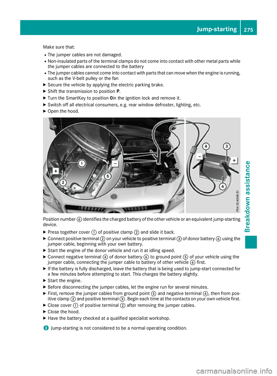
Make sure that: R
The jumper cables are not damaged. R
Non-insulated parts of the terminal clamps do not come into contact with other metal parts while
the jumper cables are connected to the battery R
The jumper cables cannot come into contact with parts that can move when the engine is running,
such as the V-belt pulley or the fan X
Secure the vehicle by applying the electric parking brake. X
Shift the transmission to position P .X
Turn the SmartKey to position 0 in the ignition lock and remove it.X
Switch off all electrical consumers, e.g. rear window defroster, lighting, etc. X
Open the hood.
Position number �
Page 279 of 318

As a rule, you should have the vehicle trans-
ported. R
towing the vehicle with a tow rope or tow bar
Only tow the vehicle in exceptional cases.
The battery must be connected and charged.
Otherwise, you: R
cannot turn the SmartKey to position 2 in the
ignition lock R
cannot release the electric parking brake R
cannot move the transmission to position N
The function of the electric parking brake and
the parking lock is dependent on the on-board
voltage.
If the on-board voltage is low or if there is a sys-
tem malfunction: R
the electric parking brake may not be applied
in certain circumstances, or R
the transmission may not be shifted to P
Switch off non-essential consumers, e.g. the
radio.
Disarm the automatic locking feature before the
vehicle is towed ( Y
page 184). You could other-
wise be locked out when pushing or towing the
vehicle.
Installing/removing the towing eye
Installing the towing eye
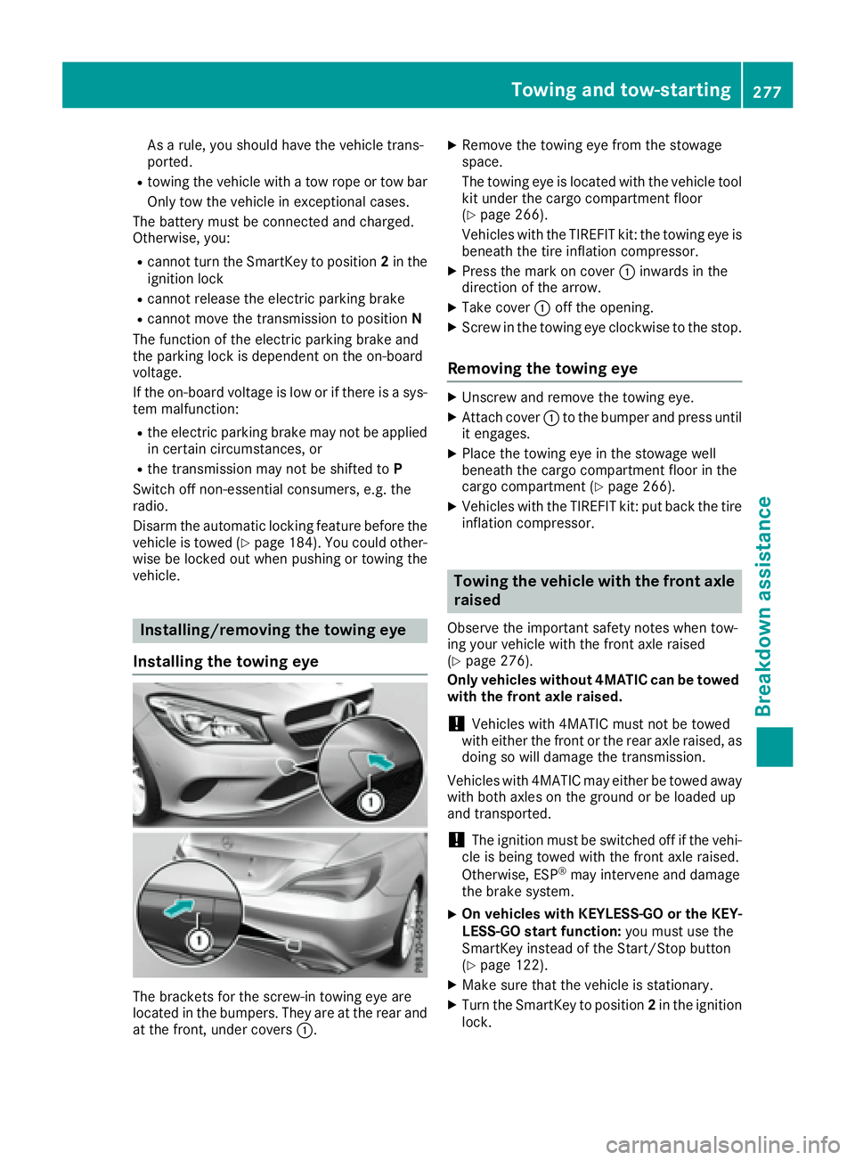
The brackets for the screw-in towing eye are
located in the bumpers. They are at the rear and
at the front, under covers �C . X
Remove the towing eye from the stowage
space.
The towing eye is located with the vehicle tool
kit under the cargo compartment floor
( Y
page 266).
Vehicles with the TIREFIT kit: the towing eye is
beneath the tire inflation compressor. X
Press the mark on cover �C inwards in the
direction of the arrow. X
Take cover �C off the opening. X
Screw in the towing eye clockwise to the stop.
Removing the towing eye X
Unscrew and remove the towing eye. X
Attach cover �C to the bumper and press until
it engages. X
Place the towing eye in the stowage well
beneath the cargo compartment floor in the
cargo compartment ( Y
page 266).X
Vehicles with the TIREFIT kit: put back the tire
inflation compressor.
Towing the vehicle with the front axle
raised Observe the important safety notes when tow-
ing your vehicle with the front axle raised
( Y
page 276).
Only vehicles without 4MATIC can be towed
with the front axle raised.
! Vehicles with 4MATIC must not be towed
with either the front or the rear axle raised, as
doing so will damage the transmission.
Vehicles with 4MATIC may either be towed away
with both axles on the ground or be loaded up
and transported.
! The ignition must be switched off if the vehi-
cle is being towed with the front axle raised.
Otherwise, ESP ®
may intervene and damage
the brake system. X
On vehicles with KEYLESS-GO or the KEY-
LESS-GO start function: you must use the
SmartKey instead of the Start/Stop button
( Y
page 122). X
Make sure that the vehicle is stationary. X
Turn the SmartKey to position 2 in the ignition
lock.Towing and tow-starting 277
Breakdo wn assis tance Z
Page 281 of 318

Notes on 4MATIC vehicles
! Vehicles with 4MATIC must not be towed
with either the front or the rear axle raised, as
doing so will damage the transmission.
Vehicles with 4MATIC may only either be towed
away with both axles on the ground or be loaded
up and transported.
If the vehicle's transmission, front, or rear axle is
damaged, have the vehicle transported on a
truck or trailer.
In the event of damage to the electrical sys-
tem:
If the battery is defective, the automatic trans-
mission will be locked in position P . To shift the
automatic transmission to position N , you must
provide power to the vehicle's electrical system
in the same way as when jump-starting
( Y
page 273).
Have the vehicle transported on a transporter or
trailer.
Tow-starting (emergency engine
starting)
! Vehicles with automatic transmission must
not be tow-started. You could otherwise dam-
age the automatic transmission.
i You can find information on "Jump-starting"
under ( Y
page 273).
Fuses
Important safety notes
G WARNING
If you manipulate or bridge a faulty fuse or if
you replace it with a fuse with a higher amper-
age, the electric cables could be overloaded.
This could result in a fire. There is a risk of an
accident and injury.
Always replace faulty fuses with the specified
new fuses having the correct amperage.
! Only use fuses that have been approved for
Mercedes-Benz vehicles and which have the
correct fuse rating for the system concerned.
Only use fuses marked with an "S". Other- wise, components or systems could be dam-
aged.
! Make sure that no moisture can enter the
fuse box when the cover is open.
! When closing the cover, make sure that it is
lying correctly on the fuse box. Moisture seep-
ing in or dirt could otherwise impair the oper-
ation of the fuses.
The fuses in your vehicle serve to close down
faulty circuits. If a fuse blows, all the compo-
nents on the circuit and their functions stop
operating.
Blown fuses must be replaced with fuses of the
same rating, which you can recognize by the
color and value. The fuse ratings are listed in the
fuse al loca tion chart.
T he fuse allocation chart is in the fuse box in the
front-passenger footwell ( Y
page 280).
If a newly inserted fuse also blows, have the
cause traced and rectified at a qualified special-
ist workshop, e.g. an authorized Mercedes-Benz
Center.
Before changing a fuse X
Secure the vehicle against rolling away
( Y
page 140). X
Switch off all electrical consumers. X
Vehicles without KEYLESS-GO: remove the
SmartKey from the ignition lock. X
Vehicles with KEYLESS-GO start-function
or KEYLESS-GO: open the driver's door.
The vehicle electronics now have status 0 .
This is the same as the SmartKey having been
removed.
The fuses are located in various fuse boxes: R
Fuse box in the engine compartment on the
left-hand side of the vehicle, when viewed in
the direction of travel R
Fuse box in the front-passenger footwell
The fuse allocation chart is on the fuse box in the
front-passenger footwell ( Y
page 280).Fuses 279
Breakdown assistance Z
Page 303 of 318

PSI (pounds per square inch) A standard unit of measure for tire pressure.
Aspect ratio Relationship between tire height and tire width
in percent.
Tire pressure This is pressure inside the tire applying an out-
ward force to each square inch of the tire's sur-
face. The tire pressure is specified in pounds per
square inch (psi), in kilopascal (kPa) or in bar.
The tire pressure should only be corrected when
the tires are cold.
Cold tire pressure The tires are cold: R
if the vehicle has been parked with the tires
out of direct sunlight for at least three hours
and R
if the vehicle has not been driven further than
1 mile (1.6 km)
Tread The part of the tire that comes into contact with
the road.
Bead The tire bead ensures that the tire sits securely
on the wheel. There are several steel wires in the
bead to prevent the tire from coming loose from
the wheel rim.
Sidewall The part of the tire between the tread and the
bead.
Weight of optional extras
The combined weight of those optional extras
that weigh more than the replaced standard
parts and more than 2.3 kg (5 lbs). These
optional extras, such as high-performance
brakes, level control, a roof rack or a high-per-
formance battery, are not included in the curb
weight and the weight of the accessories.
TIN (Tire Identification Number)
This is a unique identifier which can be used by
a tire manufacturer to identify tires, for example
for a product recall, and thus identify the pur-
chasers. The TIN is made up of the manufactur-
er's identity code, tire size, tire type code and
the manufacturing date. Load bearing index The load bearing index (also load index) is a code
that contains the maximum load bearing capa-
city of a tire.
Traction Traction is the result of friction between the tires
and the road surface.
Treadwear indicators Narrow bars (tread wear bars) that are distrib-
uted over the tire tread. If the tire tread is level
with the bars, the wear limit of �