2017 MERCEDES-BENZ B-Class lights
[x] Cancel search: lightsPage 201 of 290

Drive system
Warning/
indicator
lamp
0051 0051
Signal type
Possible causes/consequences and 0050
0050Solutions 00D9
0051
The yellow battery charge warning lamp is on.
The condition of charge of the high-voltage battery has dropped into the reserve
range.
X Charge the high-voltage battery. Driving systems
Warning/
indicator
lamp 0051 0051
Signal type
Possible causes/consequences and 0050
0050Solutions 00BA
0051
The red distance warning lamp lights up while the vehicle is in motion. A warning
tone also sounds.
You are approaching a vehicle or a stationary obstacle in your line of travel at too high a speed.
X Be prepared to brake immediately.
X Pay careful attention to the traffic situation. You may have to brake or take
evasive action.
Further information on the distance warning function of Active Brake Assist
(Y page 60). Wa
rning and indi cator lamps in the instrument cluster
199On-board computer and displays Z
Page 203 of 290
General notes
The multimedia system section in this Opera-
tor's Manual describes the basic principles for
operation. More information can be found in the Digital Operator's Manual. Important safety notes
G
WARNING
If you operate information systems and com-
munication equipment integrated in the vehi- cle while driving, you will be distracted from
traffic conditions. You could also lose control of the vehicle. There is a risk of an accident.
Only operate the equipment when the traffic
situation permits. If you are not sure that this
is possible, park the vehicle paying attention
to traffic conditions and operate the equip-
ment when the vehicle is stationary.
You must observe the legal requirements for the country in which you are currently driving whenoperating the multimedia system.
The multimedia system calculates the route to
the destination without taking the following into
account, for example:
R traffic lights
R stop and yield signs
R parking or stopping restrictions
R road narrowing
R other road and traffic rules and regulations
The multimedia system may give incorrect nav-
igation recommendations if the actual street/
traffic situation does not correspond with the
digital map's data.
For example:
R a diverted route
R the road layout or the direction of a one-way
street has been changed
For this reason, you must always observe road
and traffic rules and regulations during your
journey. Road and traffic rules and regulations
always have priority over multimedia system
driving recommendations.
Navigation announcements are intended to
direct you while driving without diverting your
attention from the road and driving. Please always use this feature instead of con-
sulting the map display for directions. Looking
at the icons or map display can distract you from traffic conditions and driving, and increase the
risk of an accident.
This equipment complies with FCC radiation
exposure limits set forth for uncontrolled equip-
ment and meets the FCC radio frequency (RF)
Exposure Guidelines in Supplement C to OET65.
This equipment has very low levels of RF energy that is deemed to comply without maximum
permissive exposure evaluation (MPE). How-
ever, it is recommended to install it at a distance
of at least 8 inches (approx. 20 cm) between the
radiation source and a person's body (not
including limbs such as hands, wrists, feet and
legs). G
WARNING
Modifications to electronic components, their software as well as wiring can impair their
function and/or the function of other net-
worked components. In particular, systems
relevant to safety could also be affected. As a
result, these may no longer function as inten-
ded and/or jeopardize the operating safety of
the vehicle. There is an increased risk of an
accident and injury.
Never tamper with the wiring as well as elec-
tronic components or their software. You
should have all work to electrical and elec-
tronic equipment carried out at a qualified
specialist workshop.
If you make any changes to the vehicle elec-
tronics, the general operating permit is ren-
dered invalid. Function restrictions
For safety reasons, some functions are restric-
ted or unavailable while the vehicle is in motion. You will notice this, for example, because either
you will not be able to select certain menu items or a message will appear to this effect. Function restrictions
201Multimedia system Z
Page 228 of 290
Currently inactive areas can be activated by text
message.
Triggering the vehicle alarm With this function, you can trigger the vehicle's
panic alarm via text message. An alarm sounds
and the exterior lighting flashes. Depending on
the setting, the panic alarm lasts five or ten sec-
onds. Afterwards, the alarm switches off. Garage door opener
General notes The HomeLink
®
garage door opener integrated
in the rear-view mirror allows you to operate up to three different door and gate systems.
Use the integrated garage door opener only on
garage doors that:
R have safety stop and reverse features and
R meet current U.S. federal safety standards
Once programed, the integrated garage door
opener in the rear-view mirror will assume the
function of the garage door system's remote
control. Please also read the operating instruc-
tions for the garage door system.
When programming a garage door opener, park
the vehicle outside the garage. Do not leave the engine running while programming.
Certain garage door drives are incompatible
with the integrated garage door opener. If you
have difficulty programing the integrated garage
door opener, contact a Mercedes-Benz Service
Center.
Alternatively, you can call the following tele-
phone assistance services:
R USA: Mercedes-Benz Customer Assistance
Center at 1-800-FOR-MERCedes
R Canada: Customer Service at
1-800-387-0100
R HomeLink ®
hotline 1-800-355-3515 (free of
charge)
More information on HomeLink ®
and/or com-
patible products is also available online at
http://www.homelink.co m.
Notes on the declaration of conformity
(Y page 26).
USA: FCC ID: CB2HMIHL4
Canada: IC: 279B-HMIHL4 Important safety notes G
WARNING
When you operate or program the garage door with the integrated garage door opener, per-
sons in the range of movement of the garage
door can become trapped or struck by the
garage door. There is a risk of injury.
When using the integrated garage door
opener, always make sure that nobody is
within the range of movement of the garage
door.
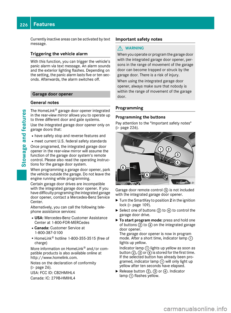
Programming Programming the buttons
Pay attention to the "Important safety notes"
(Y page 226). Garage door remote control
0083is not included
with the integrated garage door opener.
X Turn the SmartKey to position 2in the ignition
lock (Y page 109).
X Select one of buttons 0044to0085 to control the
garage door drive.
X To start program mode: press and hold one
of buttons 0044to0085 on the integrated garage
door opener.
The garage door opener is now in program
mode. After a short time, indicator lamp 0043
lights up yellow.
Indicator lamp 0043lights up yellow as soon as
button 0044,0087or0085 is stored for the first time.
If the selected button has already been pro-
gramed, indicator lamp 0043will only light up
yellow after ten seconds have elapsed.
X Release button 0044,0087or0085. Indicator
lamp 0043flashes yellow. 226
FeaturesStowage and features
Page 229 of 290

X
To program the remote control: point
garage door remote control 0083towards but-
tons 0044to0085 on the rear-view mirror at a dis-
tance of 2to 8 in (5 to 20 cm).
X Press and hold button 0084on remote control
0083 until indicator lamp 0043lights up green.
When indicator lamp 0043lights up green: pro-
gramming is finished.
When indicator lamp 0043flashes green: pro-
gramming was successful. The next step is to synchronize the rolling code (Y page 227).
X Release button 0084on remote control 0083for
the garage door drive system.
If indicator lamp 0043lights up red: repeat the
programing procedure for the corresponding
button on the rear-view mirror. When doing
so, vary the distance between remote control 0083 and the rear-view mirror.
The required distance between remote con-
trol 0083and the integrated garage door opener
depends on the garage door drive system.
Several attempts might be necessary. You
should test every position for at least
25 seconds before trying another position.
Synchronizing the rolling code
Pay attention to the "Important safety notes"
(Y page 226).
If the garage door system uses a rolling code,
you will also have to synchronize the garage
door system with the integrated garage door
opener in the rear-view mirror. To do this you will
need to use the programming button on the door
drive control panel. The programming button
may be located in different places depending on the manufacturer. It is usually located on the
door drive unit on the garage ceiling.
Familiarize yourself with the garage door drive
operating instructions, e.g. under "Program-
ming additional remote controls", before carry-
ing out the following steps.
Your vehicle must be within reach of the garage
door or gate opener drive. Make sure that nei-
ther your vehicle nor any persons/objects are
present within the sweep of the door or gate.
X Turn the SmartKey to position 2in the ignition
lock (Y page 109).
X Get out of the vehicle.
X Press the programming button on the door
drive unit.
Usually, you now have 30 second sto initiate
the next step. X
Get into the vehicle.
X Press previously programed button 0044,0087
or 0085 on the integrated garage door opener
repeatedly and in quick succession until the
door closes.
The rolling code synchronization is then com- plete.
Notes on programming the remote con-
trol
Canadian radio frequency laws require a "break"
(or interruption) of the transmission signals
after broadcasting for a few seconds. Therefore, these signals may not last long enough for the
integrated garage door opener. The signal is not
detected during programming. Comparable with Canadian law, some U.S. garage door openers
also feature a "break".
Proceed as follows:
R if you live in Canada
R if you have difficulties programming the
garage door opener (regardless of where you
live) as you follow the programming steps.
X Press and hold one of buttons 0044to0085 on the
integrated garage door opener.
After a short time, indicator lamp 0043lights up
yellow.
X Release the button.
Indicator lamp 0043flashes yellow.
X Press button 0084of garage door remote con-
trol 0083for two seconds, then release it for two
seconds.
X Press button 0084again for two seconds.
X Repeat this sequence on button 0084of remote
control 0083until indicator lamp 0043lights up
green.
When indicator lamp 0043lights up green: pro-
gramming is finished.
When indicator lamp 0043flashes green: pro-
gramming was successful. The next step is to
synchronize the rolling code.
X Release button 0084of remote control 0083of the
garage door drive.
If indicator lamp 0043lights up red: repeat the
programming process for the corresponding
button on the rear-view mirror. When doing
so, vary the distance between remote control 0083 and the rear-view mirror.
The required distance between remote con-
trol 0083and the integrated garage door opener
depends on the garage door drive system.
Several attempts might be necessary. You Features
227Stowage an d features Z
Page 230 of 290

should test every position for at least
25 seconds before trying another position.
Problems when programming If you are experiencing problems programming
the integrated garage door opener on the rear-
view mirror, take note of the following instruc-
tions:
R Check the transmitter frequency used by
garage door drive remote control 0083and
whether it is supported. The transmitter fre-
quency can usually be found on the back of
remote control 0083for the garage door drive.
The integrated garage door opener is com-
patible with devices that have units which
operate in the frequency range of 280 to
433 MHz.
R Replace the batteries in garage door remote
control 0083. This increases the likelihood that
garage door remote control 0083will transmit a
strong and precise signal to the integrated
garage door opener.
R When programming, hold remote control 0083
at varying distances and angles from but-
tons 0044to0085 which you are programming. Try
various angles at a distance between 2and
8 inches (5to 20 cm) or at the same angle but at varying distances.
R If another remote control 0083is available for
the same garage door drive, repeat the same
programming steps with this remote control
0083. Before performing these steps, make sure
that new batteries have been installed in
garage door drive remote control 0083.
R Note that some remote controls only transmit
for a limited amount of time (the indicator
lamp on the remote control goes out). Press
button 0084on remote control 0083again before
transmission ends.
R Align the antenna cable of the garage door
opener unit. This can improve signal recep-
tion/transmission.
Opening/closing the garage door After it has been programmed, the integrated
garage door opener performs the function of the
garage door system remote control. Please also read the operating instructions for the garage
door system. X
Turn the SmartKey to position 2in the ignition
lock (Y page 109).
X Press button 0044,0087or0085 which you have
programmed to operate the garage door.
Garage door system with a fixed code: indi-
cator lamp 0043lights up green.
Garage door system with a rolling code: indi-
cator lamp 0043flashes green.
The transmitter will transmit a signal as long
as the button is pressed. The transmission is
halted after a maximum of ten seconds and
indicator lamp 0043lights up yellow.
X Press button 0044,0087or0085 again if necessary.
Clearing the memory Make sure that you clear the memory of the
integrated garage door opener before selling the vehicle.
X Turn the SmartKey to position 2in the ignition
lock (Y page 109).
X Press and hold buttons 0044and 0085.
The indicator lamp initially lights up yellow
and then green.
X Release buttons 0044and 0085.
The memory of the integrated garage door
opener in the rear-view mirror is cleared. Compass
Calling up the compass 0043
Rear-view mirror
0044 Compass display
0087 Opening
The compass displays in which compass direc-
tion the vehicle is currently traveling: N N,NE
NE, E
E,
SE
SE, S
S,SW
SW, W
Wor NW
NW. 228
FeaturesStowage and features
Page 239 of 290

Always switch off the windshield wipers and
the ignition before cleaning the windshield or wiper blades.
! Only fold the windshield wipers away from
the windshield when vertical. Otherwise, you
will damage the hood.
! Do not use dry cloths, abrasive products,
solvents or cleaning agents containing sol-
vents to clean the inside of the windows. Do
not touch the insides of the windows with
hard objects, e.g. an ice scraper or ring. There is otherwise a risk of damaging the windows.
! Clean the water drainage channels of the
windshield and the rear window at regular
intervals. Deposits such as leaves, petals and
pollen may under certain circumstances pre-
vent water from draining away. This can lead
to corrosion damage and damage to elec-
tronic components.
X Clean the inside and outside of the windows
with a damp cloth and a cleaning product that is recommended and approved by Mercedes-
Benz.
Cleaning wiper blades G
WARNING
You could become trapped by the windshield wipers if they start moving while cleaning the
windshield or wiper blades. There is a risk of
injury.
Always switch off the windshield wipers and
the ignition before cleaning the windshield or
wiper blades.
! Only fold the windshield wipers away from
the windshield when vertical. Otherwise, you
will damage the hood.
! Do not pull the wiper blade. Otherwise, the
wiper blade could be damaged.
! Do not clean wiper blades too often and do
not rub them too hard. Otherwise, the graph- ite coating could be damaged. This could
cause wiper noise.
! Hold the wiper arm securely when folding
back. The windshield could be damaged if the wiper arm smacks against it suddenly. X
Fold the windshield wiper arms away from the
windshield.
X Carefully clean the wiper blades with a damp
cloth.
X Fold the windshield wiper arms back again
before switching on the ignition.
Cleaning the exterior lighting !
Only use cleaning agents or cleaning cloths
which are suitable for plastic light lenses.
Unsuitable cleaning agents or cleaning cloths
could scratch or damage the plastic light len- ses.
X Clean the plastic lenses of the exterior lights
with a wet sponge and a mild cleaning agent,
e.g. Mercedes-Benz car shampoo or cleaning
cloths.
Cleaning the mirror turn signals !
Only use cleaning agents or cleaning cloths
that are suitable for plastic lenses. Unsuitable
cleaning agents or cleaning cloths could
scratch or damage the plastic lenses of the
mirror turn signals.
X Clean the plastic lenses of the mirror turn sig-
nals in the exterior mirror housing using a wet sponge and mild cleaning agent, e.g.
Mercedes-Benz car shampoo or cleaning
cloths.
Cleaning the sensors !
If you clean the sensors with a power
washer, make sure that you keep a distance
of at least 11.8 in (30 cm) between the vehicle
and the power washer nozzle. Information
about the correct distance is available from
the equipment manufacturer. Care
237Maintenance and care Z
Page 255 of 290

Installing/removing the towing eye
Installing the towing eye The brackets for the screw-in towing eye are
located in the bumpers. They are at the rear and
at the front, under covers 0043.
X Remove the towing eye from the stowage
space.
The towing eye is located in the stowage well
under the cargo compartment floor.
Vehicles with the TIREFIT kit: the towing eye is
beneath the tire inflation compressor.
X Press the mark on cover 0043inwards in the
direction of the arrow.
X Take cover 0043off the opening.
X Screw in the towing eye clockwise to the stop.
Removing the towing eye X
Unscrew and remove the towing eye.
X Place the towing eye in the stowage well
beneath the cargo compartment floor in the
cargo compartment (Y page 241).
X Vehicles with the TIREFIT kit: put back the tire
inflation compressor. Towing a vehicle with both axles on
the ground
It is important that you observe the safety
instructions when towing away your vehicle
(Y page 251). X
Vehicles with KEYLESS-GO: use the Smart-
Key instead of the Start/Stop button
(Y page 110).
The transmission automatically shifts to posi-
tion Pwhen you open the driver's or front-
passenger door or when you remove the Smart-
Key from the ignition lock. In order to ensure
that the transmission stays in position Nwhen
towing the vehicle, you must observe the fol-
lowing points:
X Make sure that the vehicle is stationary.
X Turn the SmartKey to position 2in the ignition
lock.
X Depress and hold the brake pedal.
X Shift the transmission to position N.
X Release the brake pedal.
X Release the electric parking brake.
X Switch on the hazard warning lamps
(Y page 89).
X Leave the SmartKey in position 2in the igni-
tion lock.
If the 12 V battery indicator lamp lights up, you must observe the following points:
X Pull over and stop the vehicle safely as soon
as possible, paying attention to road and traf-
fic conditions.
X Shift the transmission to position P.
X Apply the electric parking brake.
i In order to signal a change of direction when
towing the vehicle with the hazard warning
lamps switched on, use the combination
switch as usual. In this case, only the indicator lamps for the direction of travel flash. After
resetting the combination switch, the hazard
warning lamp starts flashing again. Towing the vehicle with the front axle
raised
Observe the important safety notes when tow-
ing your vehicle with the front axle raised
(Y page 251).
! The ignition must be switched off if the vehi-
cle is being towed with the front axle raised.
Otherwise, ESP ®
may intervene and damage
the brake system. Towing
253Breakdown assistance Z
Page 266 of 290

Important safety notes
G
WARNING
Each tire, including the spare (if provided),
should be checked at least once every two
weeks when cold and inflated to the pressure recommended by the vehicle manufacturer
on the Tire and Loading Information placard
on the driver's door B-pillar or the tire pres-
sure label on the inside of the fuel filler flap. If
your vehicle has tires of a different size than
the size indicated on the Tire and Loading
Information placard or, if available, the tire
pressure label, you should determine the
proper tire pressure for those tires.
As an added safety feature, your vehicle has
been equipped with a tire pressure monitoring system (TPMS) that illuminates a low tire pres-
sure telltale when one or more of your tires
are significantly underinflated. Accordingly,
when the low tire pressure telltale lights up,
you should stop and check your tires as soon
as possible, and inflate them to the proper
pressure. Driving on a significantly underin-
flated tire causes the tire to overheat and can
lead to tire failure.
Underinflation also reduces fuel efficiency
and tire tread life, and may affect the vehicle's handling and stopping ability. Please note that the TPMS is not a substitute for proper tire
maintenance, and it is the driver's responsi-
bility to maintain correct tire pressure, even if
underinflation has not reached the level to
trigger illumination of the TPMS low tire pres-
sure telltale.
Your vehicle has also been equipped with a
TPMS malfunction indicator to indicate when
the system is not operating properly. The
TPMS malfunction indicator is combined with
the low tire pressure telltale. When the sys-
tem detects a malfunction, the warning lamp
will flash for approximately a minute and then remain continuously illuminated. This
sequence will be repeated every time the vehi- cle is started as long as the malfunction
exists. When the malfunction indicator is illu- minated, the system may not be able to detect
or signal low tire pressure as intended.
TPMS malfunctions may occur for a variety of reasons, including the installation of incom-
patible replacement or alternate tires or
wheels on the vehicle that prevent the TPMS
from functioning properly. Always check the
TPMS malfunction telltale after replacing one or more tires or wheels on your vehicle to
ensure that the replacement or alternate Tires and wheels allow the TPMS to continue to
function properly.
It is the driver's responsibility to set the tire
pressure to that recommended for cold tires
which is suitable for the operating situation
(Y page 260). Note that the correct tire pressure
for the current operating situation must first be taught-in to the tire pressure monitor. If a sub-
stantial loss of pressure occurs, the warning
threshold for the warning message is aligned to
the taught-in reference values. Restart the tire
pressure monitor after adjusting the pressure of the cold tires (Y page 265). The current pres-
sures are saved as new reference values. As a
result, a warning message will appear if the tire
pressure drops significantly.
The tire pressure monitor does not warn you of
an incorrectly set tire pressure. Observe the
notes on the recommended tire pressure
(Y page 260).
The tire pressure monitor is not able to warn you of a sudden loss of pressure, e.g. if the tire is
penetrated by a foreign object. In the event of a
sudden loss of pressure, bring the vehicle to a
halt by braking carefully. Avoid abrupt steering
movements.
The tire pressure monitor has a yellow warning
lamp in the instrument cluster for indicating
pressure loss or a malfunction. Whether the
warning lamp flashes or lights up indicates
whether a tire pressure is too low or the tire
pressure monitor is malfunctioning:
R if the warning lamp is lit continuously, the tire
pressure on one or more tires is significantly
too low. The tire pressure monitor is not mal- functioning.
R if the warning lamp flashes for around a
minute and then remains lit constantly, the
tire pressure monitor is malfunctioning.
In addition to the warning lamp, a message
appears in the multifunction display. Observe 264
Tire pressureWheels and ti
res