2017 MERCEDES-BENZ B-Class emergency towing
[x] Cancel search: emergency towingPage 20 of 290

Maximum tire load .........................2
72
Maximum tire load (definition) ....... 274
MOExtended tires .......................... 259
Optional equipment weight (defi-
nition) ............................................ 275
PSI (pounds per square inch) (def-
inition) .......................................... .275
Replacing ....................................... 275
Service life ..................................... 258
Sidewall (definition) ....................... 275
Speed rating (definition) ................ 274
Storing .......................................... .276
Structure and characteristics
(definition) ..................................... 273
Summer tires ................................. 259
Temperature .................................. 270
TIN (Tire Identification Number)
(definition) ..................................... 275
Tire bead (definition) ..................... .275
Tire pressure (definition) ................ 275
Tire pressures (recommended) ...... 274
Tire size (data) ............................... 279
Tire size designation, load-bearing capacity, speed rating .................... 270
Tire tread ....................................... 258
Tire tread (definition) ..................... 275
Total load limit (definition) ............. 275
Traction ......................................... 269
Traction (definition) ....................... 275
Tread wea r..................................... 269
Uniform Tire Quality Grading
Standards ...................................... 269
Uniform Tire Quality Grading
Standards (definition) .................... 274
Wear indicator (definition) ............. 275
Wheel rim (definition) .................... 274
see Flat tire
Top Tether ............................................ 55
Towing away
Important safety guidelines ........... 251
Installing the towing eye ................ 253
Removing the towing eye ............... 253
Transporting the vehicle ................ 254
With both axles on the ground ....... 253
With front axle raised ..................... 253
With the rear axle raised ................ 254
Towing eye ......................................... 241 Traffic reports
see also Digital Operator's Man-
ual .................................................. 201
Trailer hitch ......................................... 26
Trailer tow hitch .................................. 26
Transmission
DIRECT SELECT lever ..................... 112
Drive program ................................ 114
Driving tips .................................... 114
Engaging the drive position ............ 113
Engaging the park position ............ 112
Holding the vehicle stationary on
uphill gradients .............................. 114
Kickdown ....................................... 114
Overview ........................................ 111
Program selector button ................ 114
Shifting to neutral .......................... 113
Transmission position display ......... 112
Transmission position display
(DIRECT SELECT lever) ...................... 112
Transmission positions .................... 113
Transporting the vehicle .................. 254
Trim pieces (cleaning instruc-
tions) .................................................. 239
Trip computer (on-board com-
puter) .................................................. 156
Trip odometer
Calling up ....................................... 156
Resetting (on-board computer) ...... 158
Trunk lid
see Tailgate
Trunk load (maximum) ...................... 286
Turn signals
Display message ............................ 178
Replacing bulbs (front) ..................... 93
Switching on/of f.............................. 88
Two-way radio
Frequencies ................................... 281
Installation ..................................... 281
Transmission output (maximum) .... 281
Type identification plate
see Vehicle identification plate U
Unlocking Emergency unlocking ....................... 73 18
Index
Page 223 of 290

X
To end a call: press the0076button on the
multifunction steering wheel.
or X Press the corresponding multimedia system
button for ending a phone call.
X After the emergency call, close cover 0043.
If the mobile phone network is unavailable,
mbrace will not be able to make the emergency
call. If you leave the vehicle immediately after
pressing SOS button 0044, you do not know if
mbrace has successfully made the emergency
call. In this case, always summon assistance by other means.
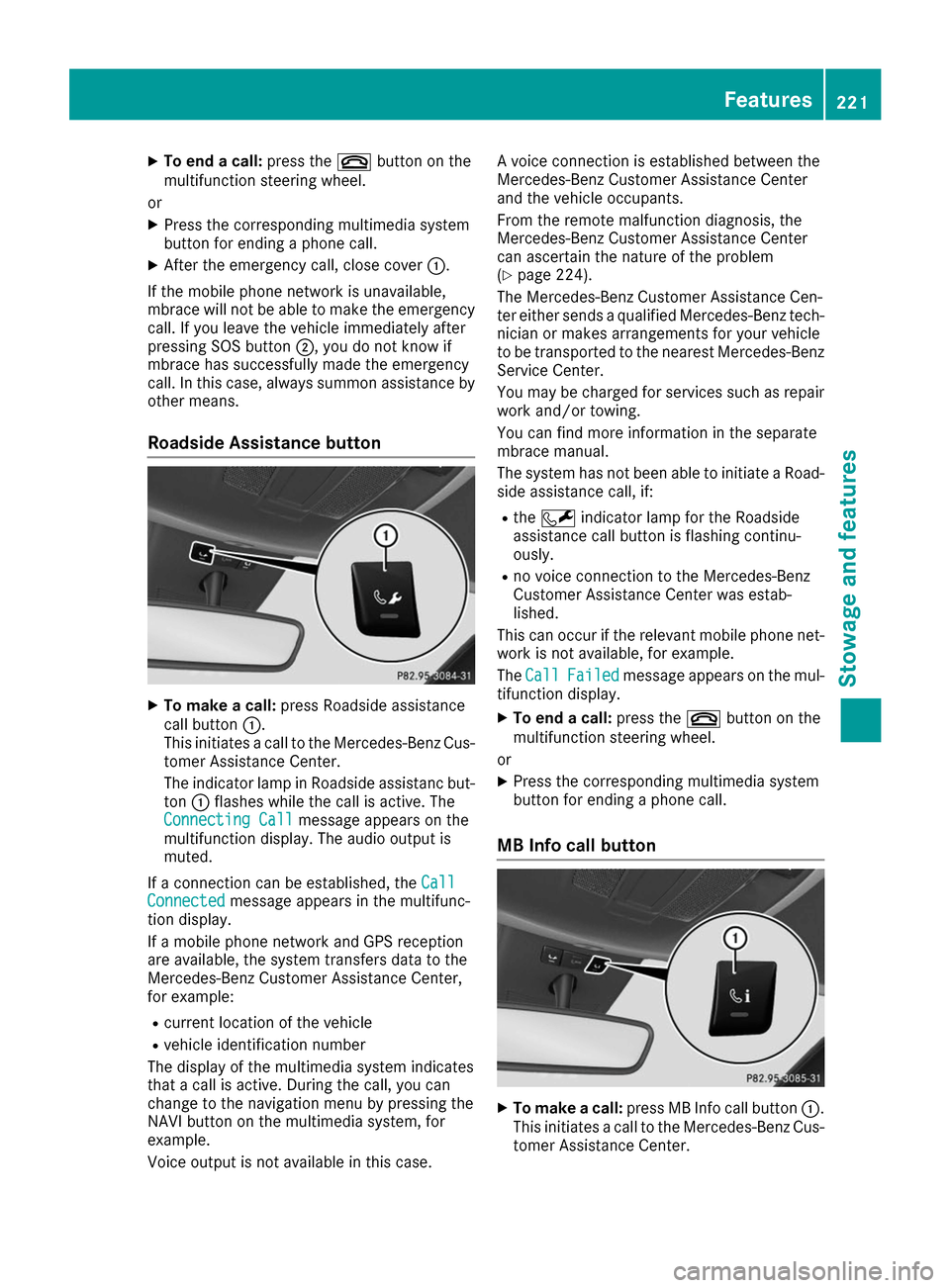
Roadside Assistance button X
To make a call: press Roadside assistance
call button 0043.
This initiates a call to the Mercedes-Benz Cus-
tomer Assistance Center.
The indicator lamp in Roadside assistanc but- ton 0043flashes while the call is active. The
Connecting Call
Connecting Call message appears on the
multifunction display. The audio output is
muted.
If a connection can be established, the Call
Call
Connected Connected message appears in the multifunc-
tion display.
If a mobile phone network and GPS reception
are available, the system transfers data to the
Mercedes-Benz Customer Assistance Center,
for example:
R current location of the vehicle
R vehicle identification number
The display of the multimedia system indicates
that a call is active. During the call, you can
change to the navigation menu by pressing the
NAVI button on the multimedia system, for
example.
Voice output is not available in this case. A voice connection is established between the
Mercedes-Benz Customer Assistance Center
and the vehicle occupants.
From the remote malfunction diagnosis, the
Mercedes-Benz Customer Assistance Center
can ascertain the nature of the problem
(Y
page 224).
The Mercedes-Benz Customer Assistance Cen-
ter either sends a qualified Mercedes-Benz tech-
nician or makes arrangements for your vehicle
to be transported to the nearest Mercedes-Benz
Service Center.
You may be charged for services such as repair work and/or towing.
You can find more information in the separate
mbrace manual.
The system has not been able to initiate a Road-
side assistance call, if:
R the 0052 indicator lamp for the Roadside
assistance call button is flashing continu-
ously.
R no voice connection to the Mercedes-Benz
Customer Assistance Center was estab-
lished.
This can occur if the relevant mobile phone net- work is not available, for example.
The Call Call Failed
Failed message appears on the mul-
tifunction display.
X To end a call: press the0076button on the
multifunction steering wheel.
or X Press the corresponding multimedia system
button for ending a phone call.
MB Info call button X
To make a call: press MB Info call button 0043.
This initiates a call to the Mercedes-Benz Cus-
tomer Assistance Center. Features
221Stowage an d features Z