Page 57 of 78

106 || 107
HANDLING THE UNEXPECTED
HANDLING THE UNEXPECTED
Emergency Engine Stop*
The ENGINE START/STOP button may be used to stop the engine due to an
emergency situation even while driving. If you must stop the engine, cho\
ose one of
the following operations:
•
Press and hold the ENGINE ST
ART/STOP button for
two seconds, or
•
Firmly press the ENGINE ST
ART/STOP button two
times.
The steering wheel will not lock. The power mode changes to ACCESSORY (\
or OFF
for manual transmission), unless the shift lever is in Park (P), in w\
hich case the
power mode changes to VEHICLE OFF.
Because turning off the engine also disables the power assist the engine\
provides
to the steering and braking systems, it will require significantly mor\
e physical effort
and time to steer and slow the vehicle. Downshift gears and use both fee\
t on the
brake pedal, if necessary, to slow the vehicle and stop immediately in a safe place.
Do not press the button while driving unless it is absolutely necessary \
for the engine
to be switched off.
*if equipped
Tire Pressure Monitoring System (TPMS)
U.S.models
Monitors the tire pressure while you are driving. If
your vehicle’s tire pressure becomes significantly low,
the low tire pressure indicator comes on.
Stop your vehicle in a safe place. Check the tire
pressure and adjust the pressure to the specified
level. The specified tire pressure is on a label on the
driver’s doorjamb.
TPMS Calibration Any time you inflate, change, or rotate one of more
of the tires, you need to recalibrate the system.
Press and hold the TPMS button. The TPMS
indicator blinks, and calibration begins.
Driving on an extremely underinflated tire can cause it to overheat. A\
n overheated
tire can fail. Always inflate your tires to the specified pressure.
NOTICE
TPMS button
Low tire pressure/TPMS indicator
Trying to lift or tow your vehicle by the bumpers will cause serious dama\
ge. The
bumpers are not designed to support the vehicle’s weight.
Improper towing such as towing behind a motorhome or other motor vehicle\
can
damage the transmission.
NOTICE
Emergency Towing
Call a professional towing service if you need to tow your vehicle.
All models
Flat bed equipment: The operator loads your vehicle on the back of a tru\
ck. This is
the best way to transport your vehicle.
2WD models
Wheel lift equipment: The tow truck uses two pivoting arms that go under\
the front
tires and lift them off the ground. The rear tires remain on the ground.\
This is an
acceptable way to tow your vehicle.
Page 58 of 78
 — Required Federal
Explanation
U.S. models only
Each tire, including the spare (")
108 || 109
HANDLING THE UNEXPECTED
HANDLING THE UNEXPECTED
Tire Pressure Monitoring System (TPMS) — Required Federal
Explanation
U.S. models only
Each tire, including the spare (if provided), should be checked monthl\
y
when cold and inflated to the inflation pressure recommended by the \
vehicle manufacturer on the vehicle placard or tire inflation pressure\
label.
(If your vehicle has tires of a different size than the size indicated \
on the
vehicle placard or tire inflation pressure label, you should determine\
the
proper tire inflation pressure for those tires.)
As an added safety feature, your vehicle has been equipped
with a tire pressure monitoring system (TPMS) that illuminates
a low tire pressure telltale when one or more of your tires is
significantly under-inflated.
Accordingly, when the low tire pressure telltale illuminates, you should
stop and check your tires as soon as possible, and inflate them to the\
proper pressure.
Driving on a significantly under-inflated tire causes the tire to overheat
and can lead to tire failure. Under-inflation also reduces fuel efficiency
and tire tread life, and may affect the vehicle’s handling and stopping
ability.
Please note that the TPMS is not a substitute for proper tire maintenanc\
e,
and it is the driver’s responsibility to maintain correct tire pressure, even
if under-inflation has not reached the level to trigger illumination of the
TPMS low tire pressure telltale.
Your vehicle has also been equipped with a TPMS malfunction indicator
to indicate when the system is not operating properly. The TPMS
malfunction indicator is combined with the low tire pressure telltale.
When the system detects a malfunction, the telltale will flash for
approximately one minute and then remain continuously illuminated. This \
sequence will continue upon subsequent vehicle start-ups as long as the \
malfunction exists.
When the malfunction indicator is illuminated, the system may not be abl\
e
to detect or signal low tire pressure as intended.
TPMS malfunctions may occur for a variety of reasons, including the
installation of replacement or alternate tires or wheels on the vehicle \
that
prevent the TPMS from functioning properly.
Always check the TPMS malfunction telltale after replacing one or
more tires or wheels on your vehicle to ensure that the replacement
or alternate tires and wheels allow the TPMS to continue to function
properly.Changing a Flat Tire
If a tire goes flat while driving, grasp the steering wheel firmly, and brake gradually
to reduce speed. Then, stop in a safe place. Replace the flat tire wit\
h the compact
spare tire. Go to a dealer as soon as possible to have the full-size tir\
e repaired or
replaced.
Getting Ready to Change the Tire
Park the vehicle on a firm, level, and non-slippery surface. Apply the\
parking
brake, shift to Park (P), and turn the vehicle off. Turn on the hazard warning lights.
1.
Open the tailgate. T
urn on the cargo lights if
necessary (see page 35).
2.
Open the cargo area floor lid.
3.
T
ake the tool case out of the cargo area.
2WD models: Take out the wheel nut wrench, jack
handle bar, and jack.
AWD models: Take out the wheel nut wrench and
jack handle bar.
4.
Unscrew the wing bolt and remove the spacer
cone. Then remove the spare tire.
5.
A
WD models: Turn the jack’s end bracket
counter-clockwise to loosen it, then remove the
jack.
6.
Place a wheel block or rock in front and rear of
the wheel diagonal to the flat tire.
7.
Place the compact spare tire (wheel side up)
under the vehicle body
, near the tire that needs
to be replaced.
8.
Loosen each wheel nut about one turn using the
wheel nut wrench.
2WD model s
Tool caseSpare tire
Jack
AWD models
Tool case
Spare tire
AWD models
Jack
Floor lid
Page 59 of 78

110 || 111
HANDLING THE UNEXPECTED
HANDLING THE UNEXPECTED
Setting Up the Jack
1.
Place the jack under the jacking point closest to
the tire to be changed.
2.
T
urn the end bracket (as shown in the image)
until the top of the jack contacts the jacking
point. Make sure that the jacking point tab is
resting in the jack notch.
3.
Raise the vehicle, using the jack handle bar and
the jack handle, until the tire is off the ground.
The following instructions must be followed to use the jack safely:
•
Do not use the jack with people or luggage in the vehicle.
•
Use the jack provided in your vehicle. Other jacks may not support the w\
eight
or
fit the jacking point.
•
Do not use while the engine is running.
•
Use only where the ground is firm and level.
•
Use only at the jacking points.
•
Do not get in the vehicle while using the jack.
•
Do not put anything on top of or underneath the jack.
Jack
handle
bar Wheel nut
Wrench as jack handle
Replacing the Flat Tire
1.
Remove the wheel nuts and flat tire.
2.
Mount the compact spare tire. Replace the
wheel nuts, and lightly tighten them.
3.
Lower the vehicle and remove the jack. T
ighten
the wheel nuts in the order indicated in the
image. Go around, tightening the nuts, two to
three times in this order. Do not overtighten the
wheel nuts.
If you drive with the spare tire installed, the low
tire pressure/TPMS indicator* appears. The
indicator stays on until a regular tire is installed.
Storing the Flat Tire 2WD models
1.
Remove the center cap.
2.
Place the flat tire face down in the spare tire
well.
3.
Remove the spacer cone from the wing bolt, flip
it over
, and insert it back on the bolt. Secure the
flat tire with the wing bolt.
4.
Securely store the wheel nut wrench, jack
handle bar
, and jack back in the tool case. Store
the case in the cargo area under the floor lid.
*if equipped
Wheel
nuts
Wing bolt
Spacer
cone
For compact spare tire
For full-size
tire
The vehicle can easily roll off the jack, seriously injuring anyone unde\
rneath.
Follow the directions for changing a tire exactly, and never get under the
vehicle when it is supported only by the jack.
WARNING
Page 60 of 78

112 || 113
HANDLING THE UNEXPECTED
HANDLING THE UNEXPECTED
Loose items can fly around the interior in a crash and can seriously i\
njure the
occupants.
Store the wheel, jack, and tools securely before driving.
WARNING
AWD models
1.
Remove the storage bag from the tool case.
2.
Put the flat tire in the storage bag and knot the
top of the bag tightly
.
3.
Poke a hole through the bag and pass the holding
belt through the hole of the bag and the wheel of
the flat tire, as shown.
4.
Place the flat tire in the cargo area, and thread
the belt through the rear anchor
, as shown.
5.
Pass the belt through the ring and tighten the belt
to secure the flat tire in place.
Belt
Rear anchor
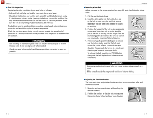
Fuse Locations
If any electrical devices are not working, turn the vehicle off and chec\
k to see if any
applicable fuse is blown. Fuse locations are shown on the fuse box cover\
. Locate the
fuse in question by the fuse number and box cover number.
Engine Compartment Fuse BoxesFuse box A
Located under the hood near the brake fluid reservoir. Push the tabs to open the
box.
Circuit ProtectedAmps1Headlight Low Beam Main20 A2CDC*(30A )3Hazard10A4DBW15 A5Wiper*(30A )6Stop10A7IGP15 A8IG Coi l15A9EOP*(10A )10INJ*(20A )11VST2*(30A )12Main Fa n30A13Starter SW*(30A )14MG Clutc h7.5A15Battery Sensor(7.5 A)16Small Light10 A17AFP Main*(10A )18Horn10A19Fog Ligh t*(10A )20SBW*(10A )
Circuit Protecte dAmps
21 Back Up Main 10A
22 Audio (10 A)
23 Sub Fan (30 A)
24 VST1
*(30 A)
25 STRLD*(7.5 A)
26 IGP CAM*(7.5A)
27 – –
28 – –
29 Back Up
*(30 A)
30 IGP LAF (7.5A)
31 IGPS (7.5 A)
32 Right Headlight Low Beam 10A
33 Left Headlight Low Beam 10A
*if equipped
Ta b
Circuit Protected Amps
1 Headlight Low Beam Main 20 A
2 CDC
*(30A )
3 Hazard 10A
4 DBW 15 A
5 Wiper
*(30A )
6 Stop 10A
7 IGP 15 A
8 IG Coil 15A
9 EOP
*(10A )
10 INJ*(20A )
11 VST2*(30A )
12 Main Fan 30A
13 Starter SW
*(30A )
14 MG Clutch 7.5A
15 Battery Sensor (7.5 A)
16 Small Light 10A
17 AFP Main
*(10A )
18 Horn 10A
19 Fog Light
*(10A )
20 SBW*(10A )
Circuit Protecte dAmps21Back Up Main10A22Audio(10 A)23Sub Fan(30 A)24VST1*(30 A)25STRLD*(7.5 A)26IGP CAM*(7.5A )27––28––29Back Up*(30 A)30IGP LAF(7.5A)31IGPS(7.5 A)32Right Headlight Low Beam10A33Left Headlight Low Beam10A
Page 61 of 78

114 || 115
HANDLING THE UNEXPECTED
HANDLING THE UNEXPECTED
Fuse box B
Pull up the cover on the + terminal, then remove it while pulling out th\
e tab, as
shown. Replacement of engine compartment fuse boxes should be done by a \
dealer.
Circuit Protecte dAmpsaBattery Main100 AbRB Main 170AcRB Main 280 AdCAP Main70 A
Ta b
*if equipped
a
b c d
Circuit ProtectedAmps1Door Lock20 A2––3Smart*(10 A)4Driver Side Door Unlock10 A5Passenger Side Door Unlock10 A6Driver Door Unlock10A7Driver Door Lock10A8Driver’s Power Window20A9Passenger’s Power Window20A10Rear Left Power Window20A11Rear Right Power Window20A12Driver Side Door Lock10A13Passenger Side Door Lock10A14––15Right Headlight High Beam10A16STS*(7.5 A)17Sunshad e*(20A )18Moonroof*(20A )19Front Seat Heater*(20A )20––
Circuit Protecte dAmps
21 MP Camera*(10 A)
22 Washer 15A
23 Rear Wiper
*(10 A)
24 A/C 7.5 A
25 Daytime Running Light s7.5 A
26 Starter Cut
*(7.5 A)
27 ABS/VSA 7.5 A
28 SRS 10A
29 Left Headlight High Beam 10A
30 ACG 10A
31 IG Relay 10 A
32 Fuel Pump 15A
33 SRS (7.5 A)
34 Meter 7.5 A
35 Mission SOL 7.5 A
36 Front ACC Socket 20A
37 ACC (7.5 A)
38 ACC
*(7.5 A)
39 Option 10A
40 Rear Wiper 10 A
41 � �
42 � �
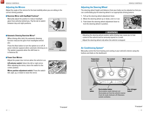
Interior Fuse Boxes
Fuse box A
Located behind the dashboard next to the steering wheel.
*if equipped
Fuse label
Circuit Protected Amps
1 Door Lock 20 A
2 – –
3 Smart
*(10 A)
4 Driver Side Door Unlock 10 A
5
Passenger Side Door Unlock10 A
6 Driver Door Unlock 10A
7 Driver Door Lock 10A
8 Driver’s Power Window 20A
9 Passenger’s Power Window 20A
10 Rear Left Power Window 20A
11 Rear Right Power Window 20A
12 Driver Side Door Lock 10A
13 Passenger Side Door Lock 10A
14 – –
15 Right Headlight High Beam 10A
16 STS
*(7.5 A)
17 Sunshade*(20A )
18 Moonroof*(2 0A )
19 Front Seat Heater*(20A )
20 – –
Circuit ProtectedAmps21MP Camera*(10 A)22Washer15A23Rear Wipe r*(10 A)24A/C7.5 A25Daytime Running Light s7.5 A26Starter Cut*(7.5 A)27ABS/VSA7.5 A28SRS10A29Left Headlight High Beam10A30ACG10A31IG Rela y10 A32Fuel Pump15 A33SRS(7.5 A)34Meter7.5 A35Mission SOL7.5 A36Front ACC Socket20A37ACC(7.5 A)38ACC*(7.5 A)39Optio n10A40Rear Wiper10 A41��42��
Page 62 of 78

116 || 117
HANDLING THE UNEXPECTED
HANDLING THE UNEXPECTED
Circuit ProtectedAmps
1
EPS70 A
IG Main30 A*1
50A*2
Fuse Box Main 250 AABS/VSA Motor40 AFuse Box Main 130AFuse Box Main 3 *40A
2 Rear Defogger30A
EPB L30A
IG Main 2*1
–*230A
–
HTR 40A
EPB
R30A
*1: Models with smart entry syste m*2: Models without smart entry system
3––
4– –
5ABS/VSA FSR30A
6D eicer*(10 A)7RR ACC SOCKET*(20 A)
8– –
9Interior Light7.5A
10 ACC Socket (Console)*(20 A)11��
12*1��12*2ACC Key Lock (7.5A)13Heated Door Mirror*(10 A)
14 A/C Blower SW*(7.5 A)15*1––15*2Wiper30 A
E-DPS * 30
A
Fuse box B
Located behind the dashboard next to the steering wheel. Remove the cove\
r by
putting a flat-tip screwdriver into the side slot, as shown.
Fuse label
*if equipped
Cover
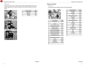
Inspecting and Changing Fuses
1.
T
urn the vehicle off, including all lights and
accessories.
2.
Check the fuses on the battery in the engine
compartment. If the fuse is blown, have it
replaced by a dealer
.
3.
Remove the fuse box cover
.
4.
Inspect the small fuses in the engine
compartment and the vehicle interior
.
If there is a blown fuse, remove it with the fuse
puller and replace it with a new one.
5.
Check the large fuse in the engine compartment.
If the fuse is blown, use a Phillips-head
screwdriver to remove the screw and replace the
fuse with a new one. Reinstall the screw
.
Replacing a fuse with one that has a higher rating greatly increases the\
chances of
damaging the electrical system.
NOTICE
Blown fuse
Fuse box on battery
Fuse puller
Combined fuse
Blown fuse
Page 63 of 78

118 || 119
MAINTENANCE
MAINTENANCE
Learn about basic maintenance that you can perform on the vehicle yourse\
lf, as well
as information about how to best maintain the vehicle.
Safety Precautions
Some of the most important safety precautions are listed below; however, we cannot
warn you of every conceivable hazard that can arise in performing mainte\
nance.
Only you can decide whether or not you should perform a given task.
Maintenance Safety
•
T
o reduce the possibility of fire or explosion, keep cigarettes, sparks\
, and flames
away from the battery and all fuel-related parts.
•
Never leave rags, towels, or other flammable objects under the hood. H\
eat
from
the engine and exhaust can ignite them, causing a fire.
•
T
o clean parts, use a commercially available degreaser or parts cleaner, not
gasoline.
•
W
ear eye protection and protective clothing when working with the battery\
or
compressed air.
•
Do not run the engine in confined spaces where carbon monoxide gas can\
accumulate.
Vehicle Safety
•
The vehicle must be stationary
, and parked on level ground with the parking
brake set and the engine off.
•
Be aware that hot parts can burn you.
•
Be aware that moving parts can injure you.
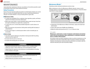
MAINTENANCEMaintenance Minder™
Reminds you when indicated maintenance service is due.
When maintenance is due, the Maintenance Minder indicator comes on and a\
message appears on the display every time you turn the vehicle on. Press\
the select/
reset knob to change displays.
Maintenance
Minder indicator
Main items
Sub items
Maintenance Minder message
• Independent of the Maintenance Minder information, replace the brake fl\
uid
every 3 years.
•
Inspect idle speed every 160,000 miles (256,000 km).
•
Adjust the valves during services A, B, 1, 2, or 3 if they are noisy
.
U.S. models
Maintenance, replacement, or repair of emissions control devices and sys\
tems
may be done by any automotive repair establishment or individuals using \
parts
that are certified to EPA standards.
According to state and federal regulations, failure to perform maintenan\
ce on the
maintenance main items marked with # will not void your emissions warranties.
However, all maintenance services should be performed in accordance with the
intervals indicated by the multi-information display.
Improperly maintaining this vehicle or failing to correct a problem befo\
re
driving can cause a crash in which you can be seriously hurt or killed. \
Always follow the inspection and maintenance recommendations according
to the schedules in this guide.
WARNING
Failure to properly follow maintenance instructions and precautions can \
cause you to be seriously hurt or killed.
Always follow the procedures and precautions in this guide.
WARNING
Page 64 of 78

120 || 121
MAINTENANCE
MAINTENANCE
Maintenance Minder Service Codes
These codes indicate what services are due on your vehicle.
*1: If a message SERVICE does not appear more than 12 months after the display is reset, change the engine oil every year.
#: See information on maintenance and emissions warranty.
CODEMaintenance Main Items
A�Replace engine oi l*1
B�Replace engine oil*1 and oil �lter
�Inspect front and rear brakes
�Inspect tie rod ends, steering gearbox, and boots
�Inspect suspension component s
�Inspect driveshaft boots
�Inspect brake hoses and lines (Including ABS/VSA)
�Inspect all �uid levels and condition of �uids
�Inspect exhaust system#
�Inspect fuel lines and connections#
*2: If you drive in dusty conditions, replace the air cleaner element every \
15,000 miles (24,000 km).
*3: If you drive primarily in urban areas that have high concentrations of s\
oot in the air from industryand diesel-powered vehicles, replace the dust and pollen �lter every \
15,000 miles (24,000 km).
*4: Driving in mountainous areas at very low vehicle speeds results in higher transmission temperatures. This requires transmission �uid changes mo\
re frequently than
recommended by the Maintenance Minder. If you regularly drive your vehic\
le under these
conditions, have the transmission �uid changed every 25,000 miles (4\
0,000 km).
CODEMaintenance Sub Items
1
�Rotate tires
2�Replace air cleaner element*2
�Replace dust and pollen �lter*3
�Inspect drive belt
3
�Replace transmission �uid*4
4�Replace spark plugs
�Inspect valve clearance
5
�Replace engine coolan t
6�Replace rear differential �uid*
Continuously variable transmission models only
Under the Hood
Opening the Hood
1.
Park the vehicle on a level surface, and set the
parking brake.
2.
Pull the hood release handle under the lower left
corner of the dashboard.
3.
Push up the hood latch lever in the center of the
hood to release the lock mechanism, and then
open the hood.
4.
Remove the support rod from the clamp using the
grip. Mount the support rod in the hood.
When closing, remove the support rod, and
stow it in the clamp, then gently lower the hood.
Remove your hand at a height of approximately
12 inches (30 cm) and let the hood close.
Engine coolant reserve tank
Washer fluid
(blue cap) Engine oil fill cap
Engine oil
dipstick (orange)
Brake/Clutch* fluid
(black cap)
Battery
Radiator cap
Lever
Support rod Grip
Clamp
Do not open the hood when the wiper arms are raised. The hood will strik\
e the
wipers, and may damage either the hood or the wipers.
NOTICE