2017 GMC SIERRA 1500 clock
[x] Cancel search: clockPage 203 of 494
GMC Sierra/Sierra Denali Owner Manual (GMNA-Localizing-U.S./Canada/
Mexico-9955992) - 2017 - crc - 5/3/16
202 Infotainment System
Viewing a Previous or Next
Picture
Touch
SorTfrom the picture
screen.
Rotating a Picture
Touch
wfrom the picture screen.
Enlarging a Picture
Touch
xfrom the picture screen.
Using the USB Picture Menu 1. Touch MENU from the picture screen.
2. Touch the appropriate menu: .Slide Show Time: Allows
selection of the slide show
interval.
. Clock, Temp. Display:
Allows selection of On or
Off to show the clock and
temperature on the full
screen.
. Display Settings: Adjusts
for Brightness and Contrast.
3. Touch
0to exit.
Auxiliary Jack
This vehicle may have an AUX jack
in the center console or armrest.
See Center Console Storage 0109.
Possible auxiliary audio sources
include:
. Laptop computer
. Audio music player
This jack is not an audio output. Do
not plug headphones into the
auxiliary input jack. Auxiliary
devices should be set up while the
vehicle is in P (Park).
Connect a 3.5 mm (1/8 in) cable
from the auxiliary device to the
auxiliary input jack.
If an auxiliary device has already
been connected, but a different
source is currently active, press the
MEDIA faceplate button repeatedly
to scroll through all of the available
audio source screens, until the AUX
source screen is shown.
Base Radio
Playing from the AUX Jack
An auxiliary device is played
through the audio system and
controlled through the device itself.
AUX Menu
Press the MENU knob to display the
AUX menu and the following may
display:
Tone Settings : Select to adjust
Bass, Midrange, Treble, Balance,
Fade, and EQ (Equalizer). See
“Tone Settings” inAM-FM Radio
(Base Radio with Touchscreen)
0 186 orAM-FM Radio (Base
Radio) 0184.
Auto Volume : If equipped, see
“Playing an Audio CD.”
DSP : If equipped, this feature
adjusts the pre-defined settings.
See “DSP” inAM-FM Radio (Base
Radio with Touchscreen) 0186 or
AM-FM Radio (Base Radio) 0184.
Page 233 of 494
GMC Sierra/Sierra Denali Owner Manual (GMNA-Localizing-U.S./Canada/
Mexico-9955992) - 2017 - crc - 5/3/16
232 Climate Controls
Automatic Operation
The system automatically controls
the fan speed, air delivery, air
conditioning, and recirculation in
order to heat or cool the vehicle to
the desired temperature.
When the indicator light is on, the
system is in full automatic operation.
If the air delivery mode or fan
setting is manually adjusted, the
auto indicator turns off and displays
will show the selected settings.
To place the system in
automatic mode:1. Press AUTO.
2. Set the driver and passenger temperature.
To find your comfort setting,
start with 22 °C (72 °F) and
allow the system time to
stabilize. Then adjust the
temperature as needed for best
comfort.
To improve fuel efficiency and to
cool the vehicle faster, recirculation
may be automatically selected in
warm weather. The recirculation light will not come
on when automatically controlled.
Press
@to manually select
recirculation; press it again to select
outside air.
Do not cover the solar sensor on the
top of the instrument panel near the
windshield. This sensor regulates
air temperature based on sun load.
See “Sensors” later in this section.
Manual Operation
O:Press to turn the climate control
system on or off. Outside air still
enters the vehicle, and is directed to
the floor. This direction can be
changed by pressing the air
delivery mode.
9: Turn clockwise or
counterclockwise to increase or
decrease the fan speed. Press the
knob to turn the fan off.
Press AUTO to return to automatic
operation. Driver and Passenger
Temperature Control :
The
temperature can be adjusted
separately for the driver and
passenger.
Turn the knob clockwise or
counterclockwise to increase or
decrease the driver or passenger
temperature setting.
SYNC : Press to link the passenger
temperature setting to the driver
setting. The SYNC indicator light will
turn on. When the passenger setting
is adjusted, the SYNC indicator light
is off.
The driver side or passenger side
temperature display shows the
temperature setting increasing or
decreasing.
Air Delivery Mode Control :
Press
Y,\,[, or-to change
the direction of the airflow. An
indicator light comes on in the
selected mode button.
Page 279 of 494
GMC Sierra/Sierra Denali Owner Manual (GMNA-Localizing-U.S./Canada/
Mexico-9955992) - 2017 - crc - 5/3/16
278 Driving and Operating
4. Shift the transmission toN (Neutral).
5. Shift the transfer case to 2
m.
6. Turn the transfer case knob clockwise to N (Neutral) until it
stops and hold it there until the
N (Neutral) light starts blinking.
This will take at least
10 seconds. Then slowly
release the dial to the 4
n
position. The N (Neutral) light
will come on when the transfer
case shift to N (Neutral) is
complete.
7. With the engine running, verify that the transfer case is in
N (Neutral) by shifting the
transmission to R (Reverse),
then to D (Drive). There should
be no movement of the vehicle
while shifting the transmission.
8. Turn the engine off, and the ignition to ACC/ACCESSORY.
9. Place the transmission shift lever in P (Park). See
Recreational Vehicle
Towing 0423. 10. Turn the ignition to LOCK/OFF.
Shifting Out of N (Neutral)
To shift:
1. Set the parking brake and apply the brake pedal.
2. Turn the ignition to ON/RUN with the engine off.
3. Shift the transmission to N (Neutral).
4. Turn the transfer case knob to 2
m.
After the transfer case has
shifted out of N (Neutral), the
N (Neutral) light will go out.
5. Release the parking brake.
Caution
Shifting the transmission into gear
before the requested mode
indicator light has stopped
flashing could damage the
transfer case. 6. Start the engine and shift the
transmission to the
desired gear.
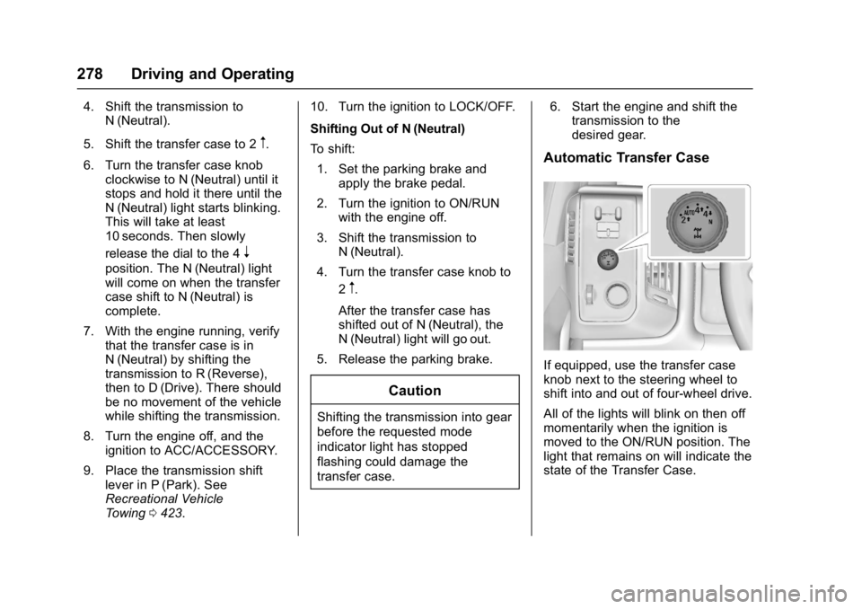
Automatic Transfer Case
If equipped, use the transfer case
knob next to the steering wheel to
shift into and out of four-wheel drive.
All of the lights will blink on then off
momentarily when the ignition is
moved to the ON/RUN position. The
light that remains on will indicate the
state of the Transfer Case.
Page 281 of 494
GMC Sierra/Sierra Denali Owner Manual (GMNA-Localizing-U.S./Canada/
Mexico-9955992) - 2017 - crc - 5/3/16
280 Driving and Operating
To shift:1. The ignition must be in ON/ RUN and the vehicle must be
stopped or moving less than
5 km/h (3 mph) with the
transmission in N (Neutral). It is
best for the vehicle to be
moving 1.6 to 3.2 km/h
(1 to 2 mph).
2. Turn the knob to 4
n. Wait for
the 4
nindicator light to stop
flashing before shifting the
transmission into gear.
Caution
Shifting the transmission into gear
before the requested mode
indicator light has stopped
flashing could damage the
transfer case.
If the transmission is in gear and/or
moving more than 5 km/h (3 mph),
the 4
nindicator light will flash for
30 seconds and not complete the
shift. After 30 seconds the transfer
case will shift to 4
m. Turn the knob to 4
mto display the indicator. With
the vehicle moving less than 5 km/h
(3 mph), and the transmission in
N (Neutral), attempt the shift again.
Shifting Out of 4
n
To shift:
1. The vehicle must be stopped or moving less than 5 km/h
(3 mph) with the transmission
in N (Neutral) and the ignition in
ON/RUN. It is best for the
vehicle to be moving
1.6 to 3.2 km/h (1 to 2 mph).
2. Turn the knob to 4
m, AUTO,
or 2
m. Wait for the 4m, AUTO,
or 2
mindicator light to stop
flashing before shifting the
transmission into gear.
Caution
Shifting the transmission into gear
before the requested mode
indicator light has stopped
flashing could damage the
transfer case. If the transmission is in gear and/or
moving more than 5 km/h (3 mph),
the 4
m, AUTO, or 2mindicator light
will flash for 30 seconds but will not
complete the shift. With the vehicle
moving less than 5 km/h (3 mph),
and the transmission in N (Neutral),
attempt the shift again.
Shifting Into N (Neutral)
To shift into N (Neutral):
1. Park the vehicle on a level surface.
2. Set the parking brake and press and hold the brake
pedal. See Parking
Brake 0282.
3. Start the vehicle or turn the ignition to ON/RUN.
4. Shift the transmission to N (Neutral).
5. Shift the transfer case to 2
m.
6. Turn the transfer case knob clockwise to N (Neutral) until it
stops and hold it there until the
N (Neutral) light starts blinking.
This will take at least
Page 360 of 494
GMC Sierra/Sierra Denali Owner Manual (GMNA-Localizing-U.S./Canada/
Mexico-9955992) - 2017 - crc - 5/3/16
Vehicle Care 359
the FULL COLD mark. If it is not,
there may be a leak in the cooling
system.
If coolant is visible but the coolant
level is not at or above the FULL
COLD mark, see“How to Add
Coolant to the Coolant Surge Tank
for Gasoline Engines,” following.
How to Add Coolant to the
Coolant Surge Tank for
Gasoline Engines
If the vehicle has a diesel engine,
see“Cooling System” in the
Duramax diesel supplement for the
proper coolant fill procedure.
{Warning
You can be burned if you spill
coolant on hot engine parts.
Coolant contains ethylene glycol
and it will burn if the engine parts
are hot enough. Do not spill
coolant on a hot engine.
Caution
This vehicle has a specific
coolant fill procedure. Failure to
follow this procedure could cause
the engine to overheat and be
severely damaged.
{Warning
Steam and scalding liquids from a
hot cooling system can blow out
and burn you badly. Never turn
the cap when the cooling system,
including the surge tank pressure
cap, is hot. Wait for the cooling
system and surge tank pressure
cap to cool.
If no coolant is visible in the surge
tank, add coolant.
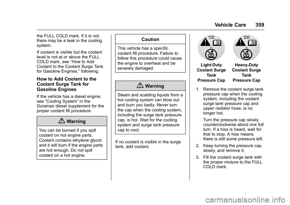
Light-Duty
Coolant Surge Tank
Pressure CapHeavy-Duty
Coolant Surge Tank
Pressure Cap
1. Remove the coolant surge tank pressure cap when the cooling
system, including the coolant
surge tank pressure cap and
upper radiator hose, is no
longer hot.
Turn the pressure cap slowly
counterclockwise about one full
turn. If a hiss is heard, wait for
that to stop. A hiss means
there is still some pressure left.
2. Keep turning the pressure cap slowly, and remove it.
3. Fill the coolant surge tank with the proper mixture to the FULL
COLD mark.
Page 375 of 494
GMC Sierra/Sierra Denali Owner Manual (GMNA-Localizing-U.S./Canada/
Mexico-9955992) - 2017 - crc - 5/3/16
374 Vehicle Care
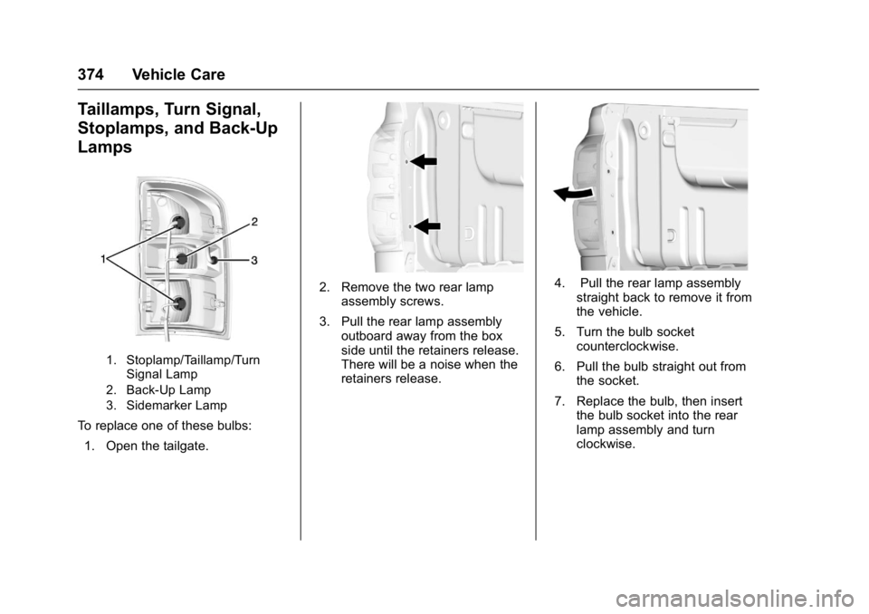
Taillamps, Turn Signal,
Stoplamps, and Back-Up
Lamps
1. Stoplamp/Taillamp/TurnSignal Lamp
2. Back-Up Lamp
3. Sidemarker Lamp
To replace one of these bulbs:
1. Open the tailgate.
2. Remove the two rear lamp assembly screws.
3. Pull the rear lamp assembly outboard away from the box
side until the retainers release.
There will be a noise when the
retainers release.4. Pull the rear lamp assemblystraight back to remove it from
the vehicle.
5. Turn the bulb socket counterclockwise.
6. Pull the bulb straight out from the socket.
7. Replace the bulb, then insert the bulb socket into the rear
lamp assembly and turn
clockwise.
Page 376 of 494
GMC Sierra/Sierra Denali Owner Manual (GMNA-Localizing-U.S./Canada/
Mexico-9955992) - 2017 - crc - 5/3/16
Vehicle Care 375
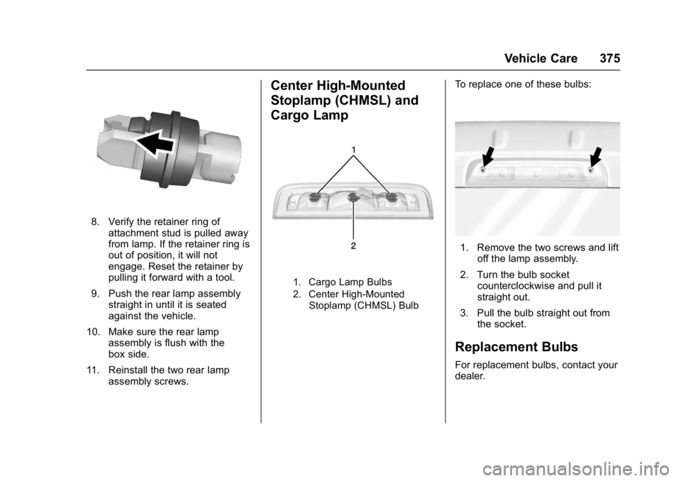
8. Verify the retainer ring ofattachment stud is pulled away
from lamp. If the retainer ring is
out of position, it will not
engage. Reset the retainer by
pulling it forward with a tool.
9. Push the rear lamp assembly straight in until it is seated
against the vehicle.
10. Make sure the rear lamp assembly is flush with the
box side.
11. Reinstall the two rear lamp assembly screws.
Center High-Mounted
Stoplamp (CHMSL) and
Cargo Lamp
1. Cargo Lamp Bulbs
2. Center High-Mounted
Stoplamp (CHMSL) Bulb
To replace one of these bulbs:
1. Remove the two screws and lift off the lamp assembly.
2. Turn the bulb socket counterclockwise and pull it
straight out.
3. Pull the bulb straight out from the socket.
Replacement Bulbs
For replacement bulbs, contact your
dealer.
Page 410 of 494
GMC Sierra/Sierra Denali Owner Manual (GMNA-Localizing-U.S./Canada/
Mexico-9955992) - 2017 - crc - 5/3/16
Vehicle Care 409
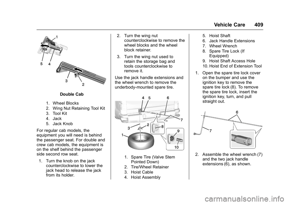
Double Cab
1. Wheel Blocks
2. Wing Nut Retaining Tool Kit
3. Tool Kit
4. Jack
5. Jack Knob
For regular cab models, the
equipment you will need is behind
the passenger seat. For double and
crew cab models, the equipment is
on the shelf behind the passenger
side second row seat.1. Turn the knob on the jack counterclockwise to lower the
jack head to release the jack
from its holder. 2. Turn the wing nut
counterclockwise to remove the
wheel blocks and the wheel
block retainer.
3. Turn the wing nut used to retain the storage bag and
tools counterclockwise to
remove it.
Use the jack handle extensions and
the wheel wrench to remove the
underbody-mounted spare tire.
1. Spare Tire (Valve Stem Pointed Down)
2. Tire/Wheel Retainer
3. Hoist Cable
4. Hoist Assembly 5. Hoist Shaft
6. Jack Handle Extensions
7. Wheel Wrench
8. Spare Tire Lock (If
Equipped)
9. Hoist Shaft Access Hole
10. Hoist End of Extension Tool
1. Open the spare tire lock cover on the bumper and use the
ignition key to remove the
spare tire lock (8). To remove
the spare tire lock, insert the
ignition key, turn, and pull
straight out.
2. Assemble the wheel wrench (7)and the two jack handle
extensions (6), as shown.