2017 FORD SUPER DUTY flat tire
[x] Cancel search: flat tirePage 408 of 636
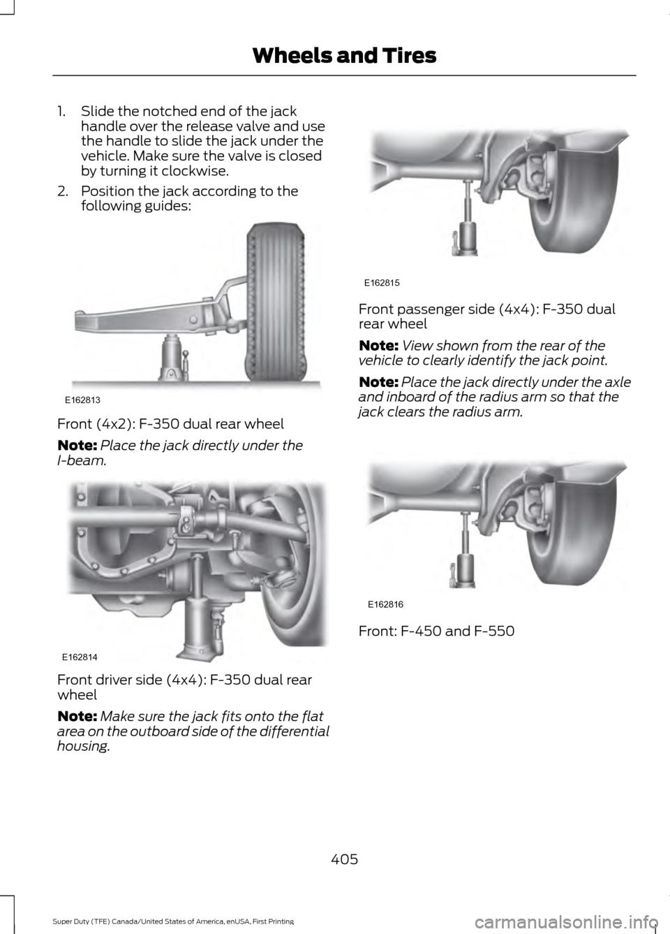
1. Slide the notched end of the jack
handle over the release valve and use
the handle to slide the jack under the
vehicle. Make sure the valve is closed
by turning it clockwise.
2. Position the jack according to the following guides: Front (4x2): F-350 dual rear wheel
Note:
Place the jack directly under the
I-beam. Front driver side (4x4): F-350 dual rear
wheel
Note:
Make sure the jack fits onto the flat
area on the outboard side of the differential
housing. Front passenger side (4x4): F-350 dual
rear wheel
Note:
View shown from the rear of the
vehicle to clearly identify the jack point.
Note: Place the jack directly under the axle
and inboard of the radius arm so that the
jack clears the radius arm. Front: F-450 and F-550
405
Super Duty (TFE) Canada/United States of America, enUSA, First Printing Wheels and TiresE162813 E162814 E162815 E162816
Page 409 of 636
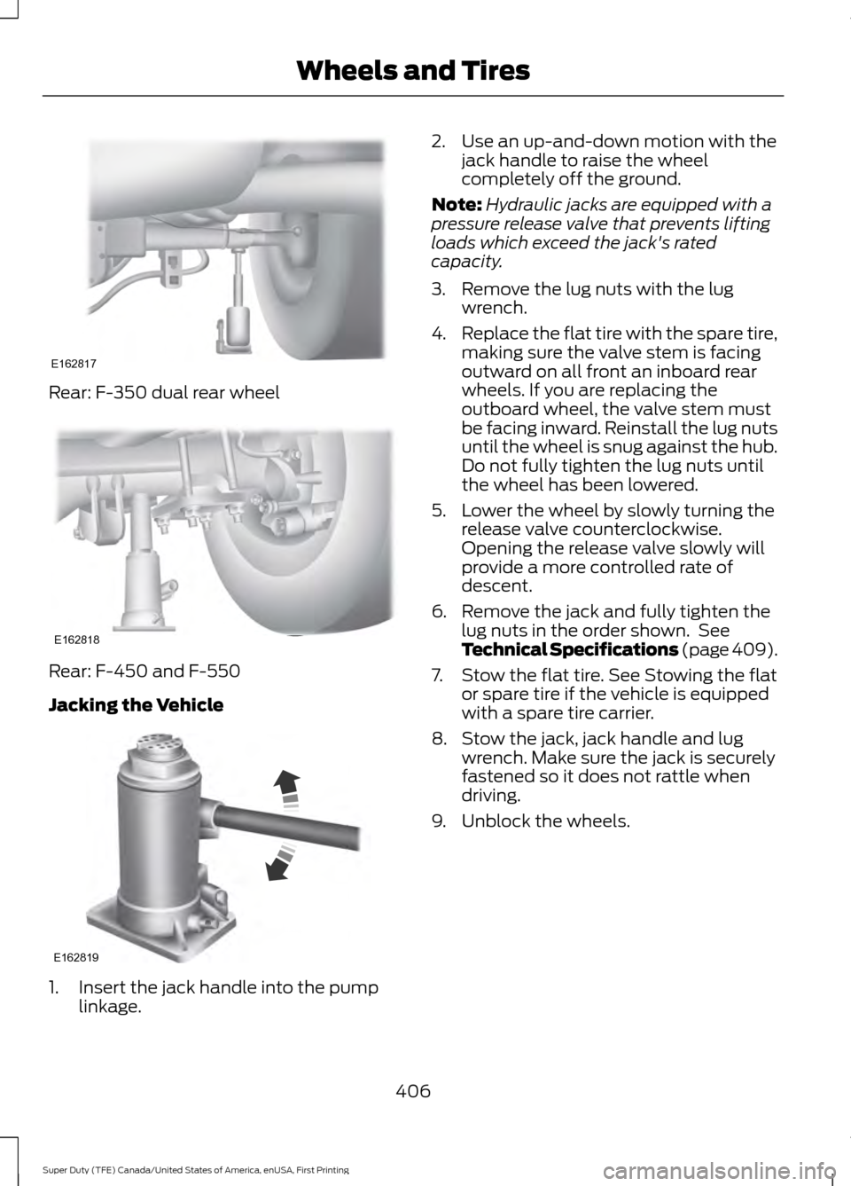
Rear: F-350 dual rear wheel
Rear: F-450 and F-550
Jacking the Vehicle
1. Insert the jack handle into the pump
linkage. 2. Use an up-and-down motion with the
jack handle to raise the wheel
completely off the ground.
Note: Hydraulic jacks are equipped with a
pressure release valve that prevents lifting
loads which exceed the jack's rated
capacity.
3. Remove the lug nuts with the lug wrench.
4. Replace the flat tire with the spare tire,
making sure the valve stem is facing
outward on all front an inboard rear
wheels. If you are replacing the
outboard wheel, the valve stem must
be facing inward. Reinstall the lug nuts
until the wheel is snug against the hub.
Do not fully tighten the lug nuts until
the wheel has been lowered.
5. Lower the wheel by slowly turning the release valve counterclockwise.
Opening the release valve slowly will
provide a more controlled rate of
descent.
6. Remove the jack and fully tighten the lug nuts in the order shown. See
Technical Specifications (page 409).
7. Stow the flat tire. See Stowing the flat or spare tire if the vehicle is equipped
with a spare tire carrier.
8. Stow the jack, jack handle and lug wrench. Make sure the jack is securely
fastened so it does not rattle when
driving.
9. Unblock the wheels.
406
Super Duty (TFE) Canada/United States of America, enUSA, First Printing Wheels and TiresE162817 E162818 E162819
Page 411 of 636
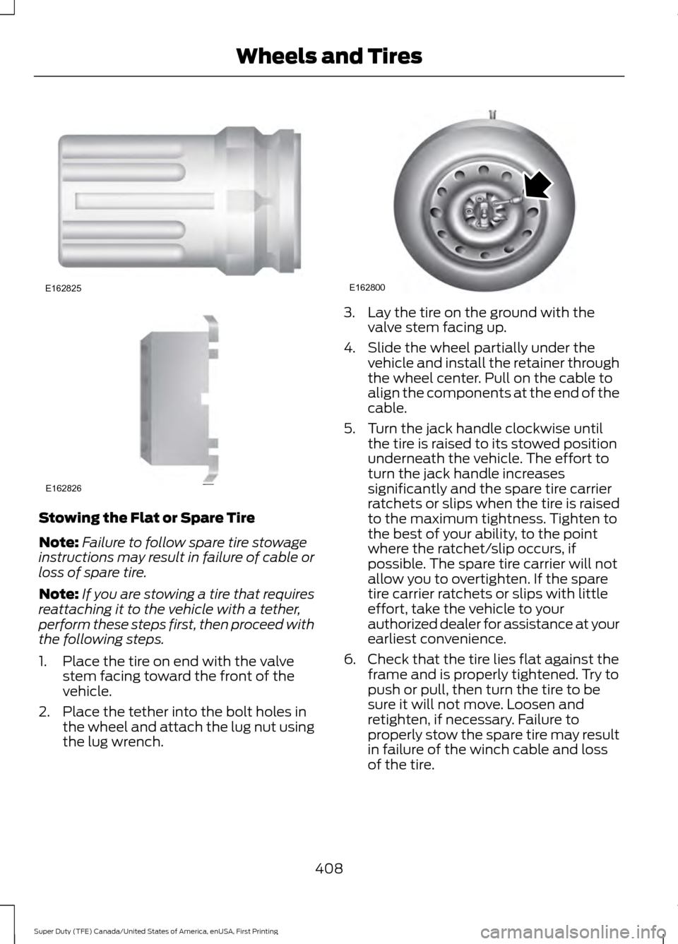
Stowing the Flat or Spare Tire
Note:
Failure to follow spare tire stowage
instructions may result in failure of cable or
loss of spare tire.
Note: If you are stowing a tire that requires
reattaching it to the vehicle with a tether,
perform these steps first, then proceed with
the following steps.
1. Place the tire on end with the valve stem facing toward the front of the
vehicle.
2. Place the tether into the bolt holes in the wheel and attach the lug nut using
the lug wrench. 3. Lay the tire on the ground with the
valve stem facing up.
4. Slide the wheel partially under the vehicle and install the retainer through
the wheel center. Pull on the cable to
align the components at the end of the
cable.
5. Turn the jack handle clockwise until the tire is raised to its stowed position
underneath the vehicle. The effort to
turn the jack handle increases
significantly and the spare tire carrier
ratchets or slips when the tire is raised
to the maximum tightness. Tighten to
the best of your ability, to the point
where the ratchet/slip occurs, if
possible. The spare tire carrier will not
allow you to overtighten. If the spare
tire carrier ratchets or slips with little
effort, take the vehicle to your
authorized dealer for assistance at your
earliest convenience.
6. Check that the tire lies flat against the frame and is properly tightened. Try to
push or pull, then turn the tire to be
sure it will not move. Loosen and
retighten, if necessary. Failure to
properly stow the spare tire may result
in failure of the winch cable and loss
of the tire.
408
Super Duty (TFE) Canada/United States of America, enUSA, First Printing Wheels and TiresE162825 E162826 E162800
Page 412 of 636
7.
Repeat this tightness check procedure
when servicing the spare tire pressure
(every six months, per scheduled
maintenance information), or at any
time that the spare tire is disturbed through service of other components.
8. If removed, install the spare tire lock into the bumper drive tube with the
spare tire lock key and jack handle.
TECHNICAL SPECIFICATIONS
Wheel Lug Nut Torque Specifications WARNING
When a wheel is installed, always remove any corrosion, dirt or foreign materials
present on the mounting surfaces of the wheel or the surface of the wheel hub,
brake drum or brake disc that contacts the wheel. Make sure that any fasteners
that attach the rotor to the hub are secured so they do not interfere with the mounting
surfaces of the wheel. Installing wheels without correct metal-to-metal contact at the
wheel mounting surfaces can cause the wheel nuts to loosen and the wheel to come off
while the vehicle is in motion, resulting in loss of control. lb.ft (Nm)
Bolt size
165 lb.ft (224 Nm)
M14 x 1.5
* Torque specifications are for nut and bolt threads free of dirt and rust. Use only Ford
recommended replacement fasteners.
On vehicles equipped with single rear wheels, retighten the lug nuts to the specified torque
at 100 miles (160 kilometers) after any wheel disturbance (such as tire rotation, changing
a flat tire, wheel removal).
On vehicles equipped with dual rear wheels, retighten the wheel lug nuts to the specified
torque at 100 miles (160 kilometers), and again at 500 miles (800 kilometers) of new
vehicle operation and after any wheel disturbance (such as tire rotation, changing a flat
tire, wheel removal).
It is important to follow the proper wheel mounting and lug nut torque procedures.
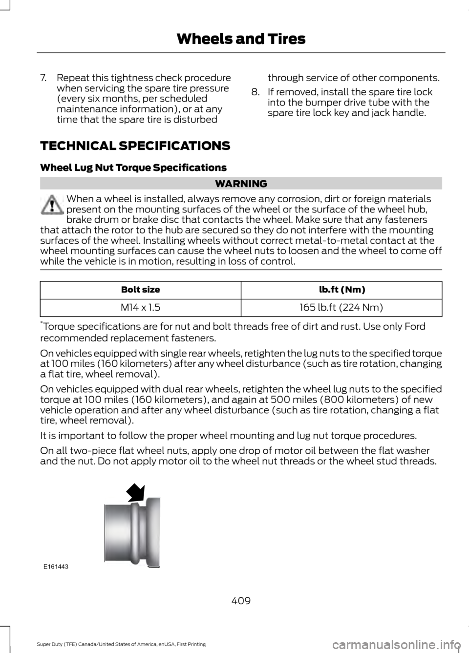
On all two-piece flat wheel nuts, apply one drop of motor oil between the flat washer
and the nut. Do not apply motor oil to the wheel nut threads or the wheel stud threads. 409
Super Duty (TFE) Canada/United States of America, enUSA, First Printing Wheels and TiresE161443
Page 568 of 636
PROTECT YOURSELF FROM THE RISING
COST OF VEHICLE REPAIRS WITH A FORD
PROTECT EXTENDED SERVICE PLAN.
Ford Protect Extended Service
Plans (U.S. Only)
Ford Protect means peace of mind. It’
s the
extended service plan backed by Ford
Motor Company, and provides more
protection beyond the New Vehicle Limited
Warranty coverage. When you visit your
Ford Dealer, Insist on genuine Ford Protect
extended service plans!
Ford Protect Can Quickly Pay for Itself
One trip to the Service Center could easily
exceed the price of your Ford Protect
Extended Service Plan. With Ford Protect
you minimize your risk for unexpected
repair bills and rising repair costs.
Up to 1,000+ Covered Vehicle
Components
There are four mechanical Ford Protect
with different levels of coverage. Ask your
authorized dealer for details.
1. PremiumCARE - Our most comprehensive coverage. With over
1,000 covered components, this plan
is so complete it’ s probably easier to
list what’ s not covered.
2. ExtraCARE - Covers 113 components, and includes many high-tech items.
3. BaseCARE - Covers 84 components.
4. PowertrainCARE - Covers 29 critical components.
Ford Protect Extended Service Plans are
honored by all authorized Ford dealers in
the U.S., Canada and Mexico. That means you get:
•
Reliable, quality service at any Ford or
Lincoln dealership.
• Repairs performed by factory trained
technicians, using genuine parts.
Rental Car Reimbursement
1st day Rental Benefit
If you bring your car into your dealer for
service, we ’ll give you a loaner to use for
the day.
Extended Rental Benefits
If your vehicle is kept overnight for covered
repairs, you are eligible for rental car
coverage, including bumper to bumper
warranty repairs, and Field Service Actions.
Roadside Assistance
Exclusive 24/7 roadside assistance,
including:
• Towing, flat-tire change and battery
jump starts.
• Out of fuel and lock-out assistance.
• Travel expense reimbursement for
lodging, meals and rental car.
• Assistance for taxi, shuttle, rental car
coverage or other transportation.
Transferable Coverage
If you sell your vehicle before your Ford
Protect plan coverage expires, you can
transfer any remaining coverage to the new
owner. Which should give you and your
potential buyer a little more peace of mind.
565
Super Duty (TFE) Canada/United States of America, enUSA, First Printing Ford Protect
Page 572 of 636
Tightening lug nuts
Tighten the lug nuts to the specified torque at 500 miles
(800 km) after any wheel disturbance (such as tire rota-
tion, changing a flat tire or wheel removal).
Vehicles with single rear
wheels
Tighten the wheel lug nuts to the specified torque at 100
miles (160 km), and again at 500 miles (800 km) of new vehicle operation and after any wheel disturbance (such as tire rotation, changing a flat tire or wheel removal).
Vehicles with dual rear
wheels
Note: Tighten the lug nuts to the specified torque. See Technical Specifications (page
409).
Multi-point Inspection
In order to keep your vehicle running right,
it is important to have the systems on your
vehicle checked regularly. This can help
identify potential issues and prevent major
problems. We recommend having the
following multi-point inspection performed
at every scheduled maintenance interval
to help make sure your vehicle keeps
running great. Multi-point inspection
Horn operation
Accessory drive belt(s)
Radiator, cooler, heater and A/C hoses
Battery performance
Suspension component for leaks ordamage
Engine and cabin air filter
Steering and linkage
Exhaust system
Tires (including spare) for wear and properpressure**
Exterior lamps and hazard warning system
operation
Windshield for cracks, chips or pits
Fluid levels *
; fill if necessary
Washer spray and wiper operation
For oil and fluid leaks
* Brake, coolant recovery reservoir, automatic transmission, power steering and window
washer.
** If your vehicle is equipped with a temporary mobility kit, check the tire sealant expiration
Use By date on the canister. Replace as needed.
569
Super Duty (TFE) Canada/United States of America, enUSA, First Printing Scheduled Maintenance
Page 629 of 636
Getting the Services You Need..............303
Away From Home............................................. 303
Global Opening
..............................................96
Opening the Windows....................................... 96
H
Handbrake See: Parking Brake............................................. 222
Hazard Warning Flashers.........................296
HDC See: Using Hill Descent Control................... 229
Headlamp Adjusting See: Adjusting the Headlamps.................... 346
Head Restraints
.............................................152
Adjusting the Head Restraint......................... 153
Heated Seats.................................................160 Rear Heated Seats............................................. 160
Heated Steering Wheel
................................82
Heated Windows and Mirrors..................150 Heated Exterior Mirrors...................................... 151
Heated Rear Window........................................ 150
Heating See: Climate Control......................................... 145
Hill Start Assist
.............................................223
Switching the System On and Off...............224
Using Hill Start Assist....................................... 223
Hints on Controlling the Interior Climate..........................................................148
Cooling the Interior Quickly............................ 149
General Hints....................................................... 148
Heating the Interior Quickly............................ 149
Recommended Settings for Cooling..........150
Recommended Settings for Heating..........149
Side Window Defogging in Cold Weather............................................................ 150
Hints on Driving With Anti-Lock Brakes............................................................222
Home Screen................................................498
Hood Lock See: Opening and Closing the Hood..........320
I
Ignition Switch
................................................173
In California (U.S. Only)............................304
Information Display Control
.......................82 Information Displays.....................................111
General Information............................................ 111
Information Messages
................................128
4WD........................................................................\
. 144
Active Park............................................................ 128
Adaptive Cruise Control................................... 129
Adaptive Steering............................................... 129
AdvanceTrac and Traction Control..............130
Airbag...................................................................... 130
Alarm and Security............................................ 130
Automatic Engine Shutdown.......................... 131
Battery and Charging System......................... 131
Blind Spot Information and Cross Traffic Alert System.................................................... 132
Collision Warning System................................ 133
Diesel Messages.................................................. 133
Doors and Locks.................................................. 135
Driver Alert............................................................ 136
Drivetrain................................................................ 136
Engine..................................................................... 136
Fuel........................................................................\
... 137
Keys and Intelligent Access............................. 137
Lane Keeping System....................................... 138
Maintenance........................................................ 138
MyKey...................................................................... 139
Off Road................................................................. 139
Park Aid.................................................................. 140
Park Brake............................................................. 140
Power Steering..................................................... 141
Remote Start......................................................... 141
Seats........................................................................\
. 141
Starting System .................................................. 142
Tire Pressure Monitoring System.................. 142
Trailer....................................................................... 142
Installing Child Restraints
............................18
Child Seats............................................................... 18
Combining Seatbelt and LATCH Lower Anchors for Attaching Child Safety
Seats..................................................................... 27
Front Seat Tether Strap Attachment (Regular Cab)................................................... 28
Rear Seat Tether Strap Attachment (Crew Cab and Super Cab)...................................... 29
Use of Inboard Lower Anchors from the Outboard Seating Positions (Center
Seating Use) .................................................... 26
Using Inflatable Seatbelts (Rear Seat Outboard Positions)....................................... 23
626
Super Duty (TFE) Canada/United States of America, enUSA, First Printing Index