2017 FORD SUPER DUTY brakes
[x] Cancel search: brakesPage 271 of 636
TOWING A TRAILER
WARNINGS
Towing trailers beyond the
maximum recommended
gross trailer weight exceeds the
limit of your vehicle and could
result in engine damage,
transmission damage, structural
damage, loss of vehicle control,
vehicle rollover and personal
injury. Do not exceed the GVWR or
the GAWR specified on the
certification label. Note:
See Recommended
Towing Weights (page 277).
Your vehicle may have electrical
items, such as fuses or relays,
related to towing. See
Fuses
(page 310).
Your vehicle's load capacity
designation is by weight, not by
volume, so you cannot necessarily
use all available space when
loading a vehicle or trailer.
Towing a trailer places an extra
load on your vehicle's engine,
transmission, axle, brakes, tires
and suspension. Inspect these
components periodically during,
and after, any towing operation. Load Placement
To help minimize how trailer
movement affects your vehicle
when driving:
•
Load the heaviest items closest
to the trailer floor.
• Load the heaviest items
centered between the left and
right side trailer tires.
• Load the heaviest items above
the trailer axles or just slightly
forward toward the trailer
tongue. Do not allow the final
trailer tongue weight to go
above or below 10-15% of the
loaded trailer weight.
• Select a ball mount with the
correct rise or drop and load
capacity. When both the
loaded vehicle and trailer are
connected, the trailer frame
should be level, or slightly
angled down toward your
vehicle, when viewed from the
side.
When driving with a trailer or
payload, a slight takeoff vibration
or shudder may be present due to
the increased payload weight.
Additional information regarding
proper trailer loading and setting
your vehicle up for towing is
located in another chapter of this
manual. See
Load Limit (page
261).
You can also find information in
the
RV & Trailer Towing Guide
available at your authorized
dealer, or online.
268
Super Duty (TFE) Canada/United States of America, enUSA, First Printing Towing
Page 273 of 636
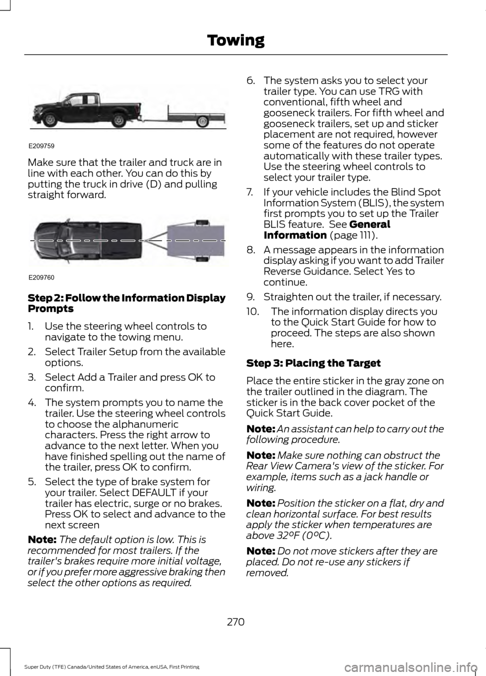
Make sure that the trailer and truck are in
line with each other. You can do this by
putting the truck in drive (D) and pulling
straight forward.
Step 2: Follow the Information Display
Prompts
1. Use the steering wheel controls to
navigate to the towing menu.
2. Select Trailer Setup from the available
options.
3. Select Add a Trailer and press OK to confirm.
4. The system prompts you to name the trailer. Use the steering wheel controls
to choose the alphanumeric
characters. Press the right arrow to
advance to the next letter. When you
have finished spelling out the name of
the trailer, press OK to confirm.
5. Select the type of brake system for your trailer. Select DEFAULT if your
trailer has electric, surge or no brakes.
Press OK to select and advance to the
next screen
Note: The default option is low. This is
recommended for most trailers. If the
trailer's brakes require more initial voltage,
or if you prefer more aggressive braking then
select the other options as required. 6. The system asks you to select your
trailer type. You can use TRG with
conventional, fifth wheel and
gooseneck trailers. For fifth wheel and
gooseneck trailers, set up and sticker
placement are not required, however
some of the features do not operate
automatically with these trailer types.
Use the steering wheel controls to
select your trailer type.
7. If your vehicle includes the Blind Spot Information System (BLIS), the system
first prompts you to set up the Trailer
BLIS feature. See General
Information (page 111).
8. A message appears in the information display asking if you want to add Trailer
Reverse Guidance. Select Yes to
continue.
9. Straighten out the trailer, if necessary.
10. The information display directs you to the Quick Start Guide for how to
proceed. The steps are also shown
here.
Step 3: Placing the Target
Place the entire sticker in the gray zone on
the trailer outlined in the diagram. The
sticker is in the back cover pocket of the
Quick Start Guide.
Note: An assistant can help to carry out the
following procedure.
Note: Make sure nothing can obstruct the
Rear View Camera's view of the sticker. For
example, items such as a jack handle or
wiring.
Note: Position the sticker on a flat, dry and
clean horizontal surface. For best results
apply the sticker when temperatures are
above
32°F (0°C).
Note: Do not move stickers after they are
placed. Do not re-use any stickers if
removed.
270
Super Duty (TFE) Canada/United States of America, enUSA, First Printing TowingE209759 E209760
Page 280 of 636
slowly turning the wheel until the trailer
is following your desired path and then
holding the wheel in that position. If
you would like to recalibrate the
system for straight backing, you can do
so with the following procedure.
•
Go into the trailer menu, select
trailer options, select change trailer
setting and then select the change
sticker option. Your saved
measurements will be displayed.
Do not change them but continue
to confirm measurements. Once
you confirm the measurements, the
system will then prompt you to
perform the calibration procedure.
Note: The system is designed to be used
with the same trailer connection every time
the trailer is chosen from the selection
menu. Using a different drawbar or a
different pin hole (on drawbars with more
than one) when connecting the drawbar to
your vehicle will affect the trailer
measurements. Take the measurements
again and update if required.
TRAILER SWAY CONTROL (If
Equipped) WARNING
Turning off trailer sway control
increases the risk of loss of vehicle
control, serious injury or death. Ford
does not recommend disabling this feature
except in situations where speed reduction
may be detrimental (such as hill climbing),
the driver has significant trailer towing
experience, and can control trailer sway
and maintain safe operation. Note:
This feature does not prevent trailer
sway, but reduces it once it begins.
Note: This feature cannot stop all trailers
from swaying. Note:
In some cases, if vehicle speed is too
high, the system may activate multiple
times, gradually reducing vehicle speed.
This feature applies your vehicle brakes at
individual wheels and, if necessary, reduces
engine power. If the trailer begins to sway,
the stability control light flashes and the
message
TRAILER SWAY REDUCE
SPEED appears in the information display.
The first thing to do is slow your vehicle
down, then pull safely to the side of the
road and check for proper tongue load and
trailer load distribution. See
Load
Carrying (page 261).
RECOMMENDED TOWING
WEIGHTS WARNING
You must use the heavy-duty
drawbar pin supplied with
your vehicle when using the
heavy-duty hitch. Failure to follow
this instruction could result in the
loss of control of your vehicle,
personal injury or death. Note:
Vehicles with a heavy-duty
hitch must use the drawbar pin
stamped 21,000 LBS. You can
obtain a replacement drawbar pin
at your Ford dealer.
Note: Make sure to take into
consideration trailer frontal area.
Do not exceed 60 feet 2
(5.6
meters 2
) trailer frontal area for
conventional trailers. Do not
exceed 75 feet 2
(6.9 meters 2
) trailer
frontal area for 5th wheel and
gooseneck trailers.
277
Super Duty (TFE) Canada/United States of America, enUSA, First Printing Towing
Page 281 of 636
Note:
Exceeding this limitation
may significantly reduce the
performance of your towing
vehicle. Selecting a trailer with a
low aerodynamic drag and rounded
front design helps optimize
performance and fuel economy.
Note: For high altitude operation,
reduce the gross combined weight
by 2% per 1000 feet (300 meters)
starting at the 1000 foot (300
meter) elevation point. Note:
Certain states require
electric trailer brakes for trailers
over a specified weight. Be sure to
check state regulations for this
specified weight. The maximum
trailer weights listed may be limited
to this specified weight, as your
vehicle's electrical system may not
include the wiring connector
needed to use electric trailer
brakes.
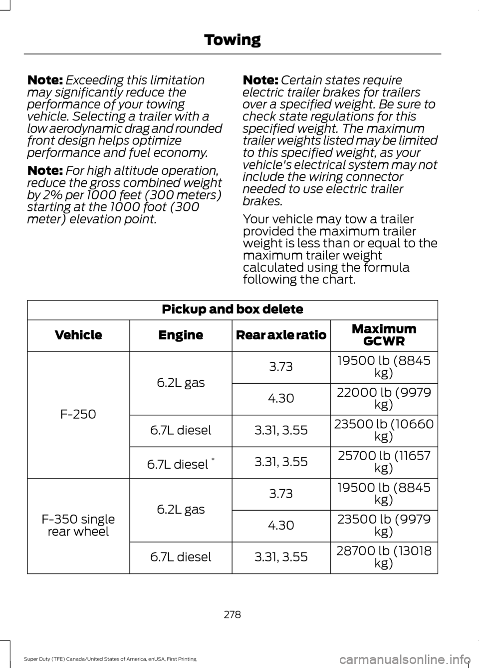
Your vehicle may tow a trailer
provided the maximum trailer
weight is less than or equal to the
maximum trailer weight
calculated using the formula
following the chart. Pickup and box delete
MaximumGCWR
Rear axle ratio
Engine
Vehicle
19500 lb (8845kg)
3.73
6.2L gas
F-250 22000 lb (9979
kg)
4.30
23500 lb (10660kg)
3.31, 3.55
6.7L diesel
25700 lb (11657kg)
3.31, 3.55
6.7L diesel *
19500 lb (8845kg)
3.73
6.2L gas
F-350 single
rear wheel 23500 lb (9979
kg)
4.30
28700 lb (13018kg)
3.31, 3.55
6.7L diesel
278
Super Duty (TFE) Canada/United States of America, enUSA, First Printing Towing
Page 285 of 636
When attaching the trailer wiring connector
to your vehicle, only use a proper fitting
connector that works with the vehicle and
trailer functions. Some seven-position
connectors may have the SAE J2863 logo,
which confirms that it is the proper wiring
connector and works correctly with your
vehicle.
Function
Color
Left turn signal and stop lamp
Yellow
Ground (-)
White
Electric brakes
Blue
Right turn signal and stop
lamp
Green
Battery (+)
Orange
Running lights
Brown
Reverse lights
Grey
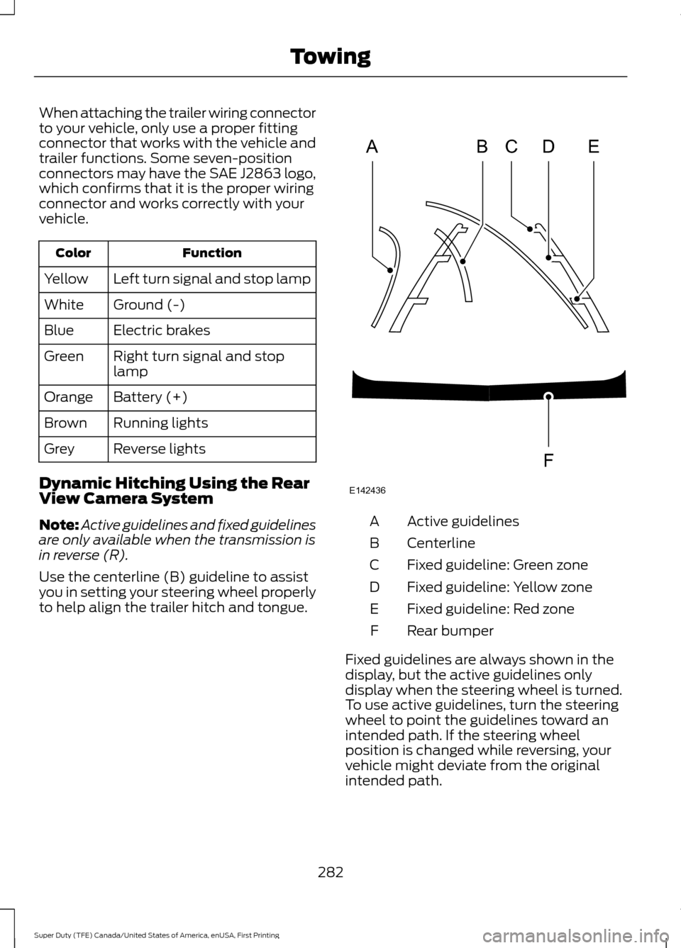
Dynamic Hitching Using the Rear
View Camera System
Note: Active guidelines and fixed guidelines
are only available when the transmission is
in reverse (R).
Use the centerline (B) guideline to assist
you in setting your steering wheel properly
to help align the trailer hitch and tongue. Active guidelines
A
Centerline
B
Fixed guideline: Green zone
C
Fixed guideline: Yellow zone
D
Fixed guideline: Red zone
E
Rear bumper
F
Fixed guidelines are always shown in the
display, but the active guidelines only
display when the steering wheel is turned.
To use active guidelines, turn the steering
wheel to point the guidelines toward an
intended path. If the steering wheel
position is changed while reversing, your
vehicle might deviate from the original
intended path.
282
Super Duty (TFE) Canada/United States of America, enUSA, First Printing TowingABCD
F
E
E142436
Page 287 of 636
Once the trailer is level or slightly nose
down toward the vehicle:
•
Lock the bar tension adjuster in place.
• Check that the trailer tongue securely
attaches and locks onto the hitch.
• Install safety chains, lighting, and trailer
brake controls as required by law or the
trailer manufacturer.
Fifth-wheel Trailer Hitch (If Equipped)
Note: The mounting pads in the bed are
specifically designed for certain fifth-wheel
trailer hitches and gooseneck ball hitches.
Do not use these mounting pads for other
purposes.
Note: Contact an authorized dealer to
purchase gooseneck and fifth-wheel hitches
that are compatible with your vehicle.
Your vehicle may be equipped with a
fifth-wheel prep package. This package
enables your vehicle to accept certain
fifth-wheel trailer hitches and gooseneck
ball hitches. The fifth-wheel trailer hitch
attaches to the four mounting pads in the
pick-up bed. An optional 7-pin trailer wiring
connector may be in the bed as well. The
gooseneck ball hitch is a separate
mounting pad from the fifth-wheel hitch,
located in the center of the bed.
Shorter pick-up boxes, such as the 6½-foot
box on the F-250 and F-350, provide less
clearance between the cab and the
fifth-wheel and gooseneck trailer
compared to longer box pick-ups, such as
an 8-foot box on the F-250 or F-350. When
selecting a trailer and tow vehicle, it is
critical to check that this combination
provides clearance between the front of
the trailer and tow vehicle for turns up to
90 degrees. Failure to follow this recommendation could result in the trailer
contacting the cab of the tow vehicle
during tight turns that are typical during
low-speed parking and turning maneuvers.
This contact could result in damage to the
trailer and tow vehicle.
Safety Chains
Note:
Do not attach safety chains to the
bumper.
Always connect the safety chains to the
frame or hook retainers of your vehicle
hitch.
To connect the safety chains, cross the
chains under the trailer tongue and allow
enough slack for turning tight corners. Do
not allow the chains to drag on the ground.
Trailer Brakes WARNING
Do not connect a trailer's hydraulic
brake system directly to your
vehicle's brake system. Your vehicle
may not have enough braking power and
your chances of having a collision greatly
increase. Electric brakes and manual, automatic or
surge-type trailer brakes are safe if you
install them properly and adjust them to
the manufacturer's specifications. The
trailer brakes must meet local and federal
regulations.
The rating for the tow vehicle's braking
system operation is at the gross vehicle
weight rating, not the gross combined
weight rating.
Separate functioning brake systems
are required for safe control of towed
vehicles and trailers weighing more
than 1500 pounds (680 kilograms)
when loaded.
284
Super Duty (TFE) Canada/United States of America, enUSA, First Printing Towing
Page 288 of 636
Integrated Trailer Brake Controller
(If Equipped)
WARNINGS
The anti-lock brake system does not
control the trailer brakes.
Use the integrated trailer brake
controller to properly adjust the
trailer brakes and check all
connections before towing a trailer. Failure
to follow this instruction could result in the
loss of control of your vehicle, personal
injury or death. Note:
The integrated Ford brake controller
is compatible with trailers equipped with
electric-actuated drum brakes and
electric-over hydraulic brake systems.
Note: The integrated Ford brake controller
does not control hydraulic surge-style
brakes. When used properly, the trailer brake
controller assists in smooth and effective
trailer braking by powering the trailer
’s
electric or electric-over-hydraulic brakes
with a proportional output based on the
towing vehicle ’s brake pressure.
You can adjust the amount of initial trailer
brake output by selecting one of three
settings through the message center. Ford has tested the trailer brake controller
to be compatible with several major
brands of electric-over-hydraulic trailer
brakes. Contact an authorized dealer for
information on which brands you can use.
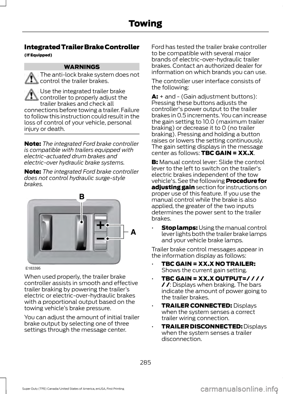
The controller user interface consists of
the following:
A: + and - (Gain adjustment buttons):
Pressing these buttons adjusts the
controller's power output to the trailer
brakes in 0.5 increments. You can increase
the gain setting to 10.0 (maximum trailer
braking) or decrease it to 0 (no trailer
braking). Pressing and holding a button
raises or lowers the setting continuously.
The gain setting displays in the message
center as follows:
TBC GAIN = XX.X.
B:
Manual control lever: Slide the control
lever to the left to switch on the trailer's
electric brakes independent of the tow
vehicle's. See the following Procedure for
adjusting gain section for instructions on
proper use of this feature. If you use the
manual control while the brake is also
applied, the greater of the two inputs
determines the power sent to the trailer
brakes.
• Stop lamps: Using the manual control
lever lights both the trailer brake lamps
and your vehicle brake lamps.
Trailer brake control messages appear in
the information display as follows:
• TBC GAIN = XX.X NO TRAILER:
Shows the current gain setting.
• TBC GAIN = XX.X OUTPUT=/ / / /
/ /
: Displays when braking. The bars
indicate the amount of power going to
the trailer brakes.
• TRAILER CONNECTED:
Displays
when the system senses a correct
trailer wiring connection.
• TRAILER DISCONNECTED: Displays
when the system senses a trailer
disconnection.
285
Super Duty (TFE) Canada/United States of America, enUSA, First Printing TowingE183395
Page 289 of 636
Procedure for Setting Trailer Brake
Controller Effort
Choose either the electric option for trailers
with electromagnetic drum brakes, or the
electric over hydraulic option for trailers
with these brake systems.
Trailer Brake Effort Setting
The trailer brake controller allows the user
to customize how aggressively the trailer
brakes engage. The default value is the low
setting and is the recommended setting
for most trailers. If your trailer's brakes
require more initial voltage, or if you prefer
more aggressive trailer braking, then select
either the medium or the high setting.
Procedure for Setting Trailer Brake
Controller Mode
Choose the low, medium or high setting
for the required initial trailer brake output.
Procedure for Adjusting Gain
Note:
Only perform this procedure in a
traffic-free environment at speeds of
approximately 20-25 mph (30-40 km/h).
The gain setting adjusts the trailer brake
controller for the specific towing condition.
You should change the setting as towing
conditions change. Changes to towing
conditions include trailer load, vehicle load,
road conditions and weather.
The gain should be set to provide the
maximum trailer braking assistance while
making sure the trailer wheels do not lock
when using the brakes. Locked trailer
wheels may lead to trailer instability.
1. Make sure the trailer brakes are in good
working condition, functioning normally
and properly adjusted. See your trailer
dealer if necessary.
2. Hook up the trailer and make the electrical connections according to the
trailer manufacturer's instructions. 3. When you plug in a trailer with electric
or electric-over-hydraulic brakes, a
confirmation message appears in the
information display.
4. Use the gain adjustment (+ and -) buttons to increase or decrease the
gain setting to the desired starting
point. A gain setting of 6.0 is a good
starting point for heavier loads.
5. In a traffic-free environment, tow the trailer on a dry, level surface at a speed
of 20-25 mph (30-40 km/h) and
squeeze the manual control lever
completely.
6. If the trailer wheels lock up, indicated by squealing tires, reduce the gain
setting. If the trailer wheels turn freely,
increase the gain setting. Repeat Steps
5 and 6 until the gain setting is at a
point just below trailer wheel lock-up.
If towing a heavier trailer, trailer wheel
lock-up may not be attainable even
with the maximum gain setting of 10.
Information Display Warning Messages
Note: An authorized dealer can diagnose
the trailer brake controller to determine
exactly which trailer fault has occurred.
However, your Ford warranty does not cover
this diagnosis if the fault is with the trailer.
TRAILER BRAKE MODULE FAULT
Displays in response to faults sensed by
the trailer brake controller, accompanied
by a single tone. If this message appears,
contact an authorized dealer as soon as
possible for diagnosis and repair. The
controller may still function, but with
degraded performance.
WIRING FAULT ON TRAILER
Displays when there is a short circuit on
the electric brake output wire.
286
Super Duty (TFE) Canada/United States of America, enUSA, First Printing Towing