2017 FORD SUPER DUTY ECU
[x] Cancel search: ECUPage 133 of 636
AdvanceTrac and Traction Control
Action
Message
The system detects a condition that requires service. Contactan authorized dealer as soon as possible.
Service AdvanceTrac
The status of the AdvanceTrac system after you switched it off.
AdvanceTrac Off
The status of the AdvanceTrac system after you switched it on.
AdvanceTrac On
The status of the AdvanceTrac sport mode after you switched it on.
AdvanceTrac SPORT
MODE
The status of the traction control system after you switchedit off. See Using Traction Control (page 225).
Traction Control Off
The status of the traction control system after you switchedit on. See
Using Traction Control (page 225).
Traction Control On
Airbag Action
Message
Displays when the system detects a malfunction due to a blocked sensor.
Occupant Sensor
BLOCKED Remove
Objects Near Passenger Seat
Alarm and Security Action
Message
Alarm triggered due to unauthorized entry. See
Anti-Theft
Alarm (page 76).
Vehicle Alarm To Stop
Alarm, Start Vehicle.
130
Super Duty (TFE) Canada/United States of America, enUSA, First Printing Information Displays
Page 161 of 636
Saving a Preset Position
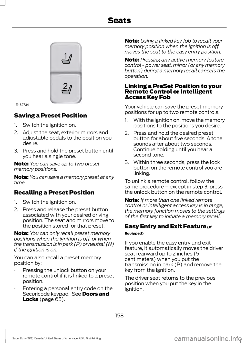
1. Switch the ignition on.
2. Adjust the seat, exterior mirrors and
adjustable pedals to the position you
desire.
3. Press and hold the preset button until you hear a single tone.
Note: You can save up to two preset
memory positions.
Note: You can save a memory preset at any
time.
Recalling a Preset Position
1. Switch the ignition on.
2. Press and release the preset button associated with your desired driving
position. The seat and mirrors move to
the position stored for that preset.
Note: You can only recall preset memory
positions when the ignition is off, or when
the transmission is in park (P) or neutral (N)
if the ignition is on.
You can also recall a preset memory
position by:
• Pressing the unlock button on your
remote control if it is linked to a preset
position.
• Entering a personal entry code on the
Securicode keypad. See Doors and
Locks (page 65). Note:
Using a linked key fob to recall your
memory position when the ignition is off
moves the seat to the easy entry position.
Note: Pressing any active memory feature
control - power seat, mirror (or any memory
button) during a memory recall cancels the
operation.
Linking a PreSet Position to your
Remote Control or Intelligent
Access Key Fob
Your vehicle can save the preset memory
positions for up to two remote controls.
1. With the ignition on, move the memory
positions to the positions you desire.
2. Press and hold the desired preset button for about five seconds. A tone
sounds after about two seconds.
Continue holding until you hear a
second tone.
3. Within three seconds, press the lock button on the remote control you are
linking.
To unlink a remote control, follow the
same procedure – except in step 3, press
the unlock button on the remote control.
Note: If more than one linked remote
control or intelligent access key is in range,
the memory function moves to the settings
of the first key to initiate a memory recall.
Easy Entry and Exit Feature
(If
Equipped)
If you enable the easy entry and exit
feature, it automatically moves the driver
seat rearward up to 2 inches (5
centimeters) when you put the
transmission in park (P) and remove the
key from the ignition.
The driver seat returns to the previous
position when you put the key in the
ignition.
158
Super Duty (TFE) Canada/United States of America, enUSA, First Printing Seats21
E162734
Page 167 of 636
HomeLink Wireless Control
System
WARNINGS
Make sure that the garage door and
security device are free from
obstruction when you are
programming. Do not program the system
with the vehicle in the garage. Do not use the system with any
garage door opener that does not
have the safety stop and reverse
feature as required by U.S. Federal Safety
Standards (this includes any garage door
opener manufactured before April 1, 1982).
A garage door opener which cannot detect
an object, signaling the door to stop and
reverse, does not meet current federal
safety standards. Using a garage door
opener without these features increases
the risk of serious injury or death. Note:
Make sure you keep the original
remote control transmitter for use in other
vehicles as well as for future system
programming.
Note: We recommend that upon the sale
or lease termination of your vehicle, you
erase the programmed function buttons for
security reasons. See Erasing the Function
Button Codes later in this section.
Note: You can program a maximum of
three devices. To change or replace any of
the three devices after it has been initially
programmed, you must first erase the
current settings. See Erasing the Function
Button Codes
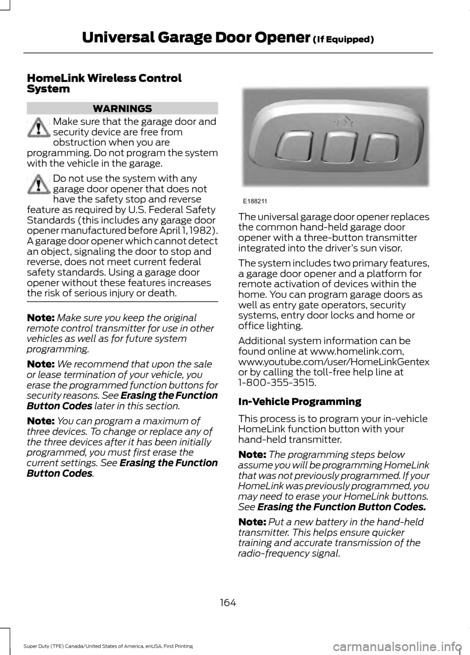
. The universal garage door opener replaces
the common hand-held garage door
opener with a three-button transmitter
integrated into the driver
’s sun visor.
The system includes two primary features,
a garage door opener and a platform for
remote activation of devices within the
home. You can program garage doors as
well as entry gate operators, security
systems, entry door locks and home or
office lighting.
Additional system information can be
found online at www.homelink.com,
www.youtube.com/user/HomeLinkGentex
or by calling the toll-free help line at
1-800-355-3515.
In-Vehicle Programming
This process is to program your in-vehicle
HomeLink function button with your
hand-held transmitter.
Note: The programming steps below
assume you will be programming HomeLink
that was not previously programmed. If your
HomeLink was previously programmed, you
may need to erase your HomeLink buttons.
See
Erasing the Function Button Codes.
Note: Put a new battery in the hand-held
transmitter. This helps ensure quicker
training and accurate transmission of the
radio-frequency signal.
164
Super Duty (TFE) Canada/United States of America, enUSA, First Printing Universal Garage Door Opener
(If Equipped)E188211
Page 208 of 636
AUTOMATIC TRANSMISSION
WARNING
Always apply the parking brake fully
and make sure you shift into park (P).
Switch the ignition off and remove
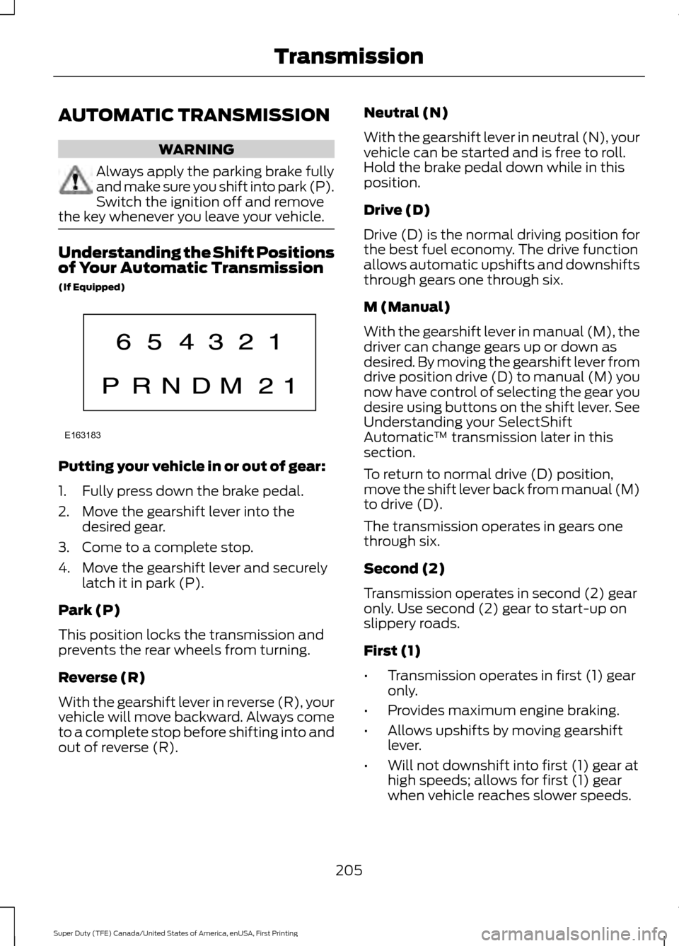
the key whenever you leave your vehicle. Understanding the Shift Positions
of Your Automatic Transmission
(If Equipped)
Putting your vehicle in or out of gear:
1. Fully press down the brake pedal.
2. Move the gearshift lever into the
desired gear.
3. Come to a complete stop.
4. Move the gearshift lever and securely latch it in park (P).
Park (P)
This position locks the transmission and
prevents the rear wheels from turning.
Reverse (R)
With the gearshift lever in reverse (R), your
vehicle will move backward. Always come
to a complete stop before shifting into and
out of reverse (R). Neutral (N)
With the gearshift lever in neutral (N), your
vehicle can be started and is free to roll.
Hold the brake pedal down while in this
position.
Drive (D)
Drive (D) is the normal driving position for
the best fuel economy. The drive function
allows automatic upshifts and downshifts
through gears one through six.
M (Manual)
With the gearshift lever in manual (M), the
driver can change gears up or down as
desired. By moving the gearshift lever from
drive position drive (D) to manual (M) you
now have control of selecting the gear you
desire using buttons on the shift lever. See
Understanding your SelectShift
Automatic
™ transmission later in this
section.
To return to normal drive (D) position,
move the shift lever back from manual (M)
to drive (D).
The transmission operates in gears one
through six.
Second (2)
Transmission operates in second (2) gear
only. Use second (2) gear to start-up on
slippery roads.
First (1)
• Transmission operates in first (1) gear
only.
• Provides maximum engine braking.
• Allows upshifts by moving gearshift
lever.
• Will not downshift into first (1) gear at
high speeds; allows for first (1) gear
when vehicle reaches slower speeds.
205
Super Duty (TFE) Canada/United States of America, enUSA, First Printing TransmissionE163183
Page 211 of 636
Automatic Transmission Adaptive
Learning
This feature's design is to increase
durability and provide consistent shift feel
over the life of your vehicle. A new vehicle
or transmission may have firm shifts, soft
shifts or both. This operation is normal and
does not affect function or durability of the
transmission. Over time, the adaptive
learning process fully updates transmission
operation. Additionally, whenever you
disconnect the battery or install a new
battery, the system must relearn the
strategy.
Brake-Shift Interlock
WARNINGS
Do not drive your vehicle until you
verify that the brake lamps are
working.
When doing this procedure, you need
to take the transmission out of park
(P) which means your vehicle can
roll freely. To avoid unwanted vehicle
movement, always fully apply the parking
brake prior to doing this procedure. Use
wheels chocks if appropriate. If the parking brake is fully released,
but the brake warning lamp remains
illuminated, the brakes may not be
working properly. Have your vehicle
checked as soon as possible. Your vehicle is equipped with a brake-shift
interlock feature that prevents the
gearshift lever from moving from park (P)
when the ignition is on and the brake pedal
is not pressed.
If you cannot move the gearshift lever out
of park (P) position with the ignition is on
and the brake pedal pressed, a malfunction
may have occurred. It is possible that a
fuse has blown or your vehicle
’s brake
lamps are not operating properly. See
Fuse Specification Chart (page 310). If the fuse is not blown and the brake
lamps are working properly, the following
procedure allows you to move the gearshift
lever from park (P):
1. Apply the parking brake. Switch the
ignition key to 1 (off), then remove the
key.
2. Move the steering column to the full down and full rearward position
(toward the driver ’s seat).
3. Remove the gearshift lever boot.
4. Place fingers into hole where you removed the gearshift lever boot and
pull top half of shroud up and forward
to separate it from the lower half of the
shroud. There is a hinge at the forward
edge of the top shroud. Roll the top
half of the shroud upward on the hinge
point to clear the hazard flasher button,
then pull straight rearward toward the
driver ’s seat to remove.
5. Remove the top half of the shroud.
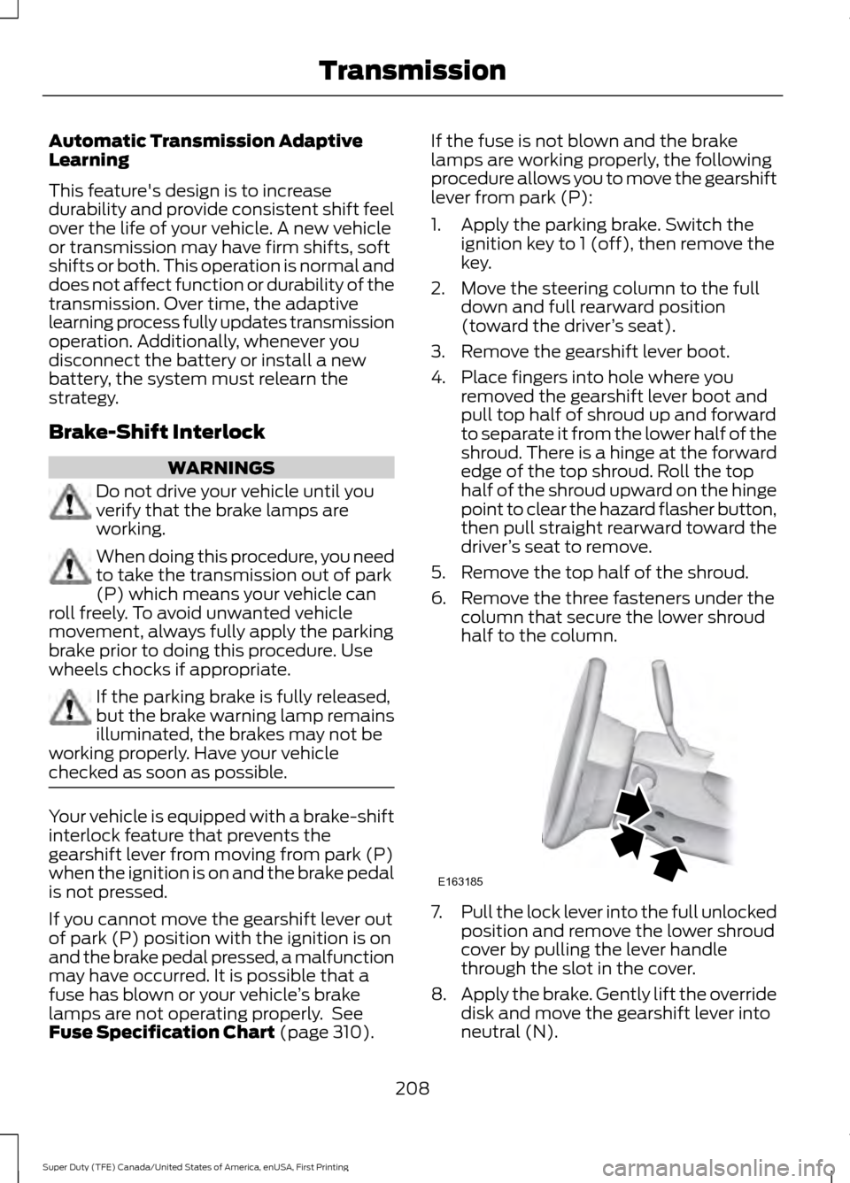
6. Remove the three fasteners under the column that secure the lower shroud
half to the column. 7.
Pull the lock lever into the full unlocked
position and remove the lower shroud
cover by pulling the lever handle
through the slot in the cover.
8. Apply the brake. Gently lift the override
disk and move the gearshift lever into
neutral (N).
208
Super Duty (TFE) Canada/United States of America, enUSA, First Printing TransmissionE163185
Page 270 of 636
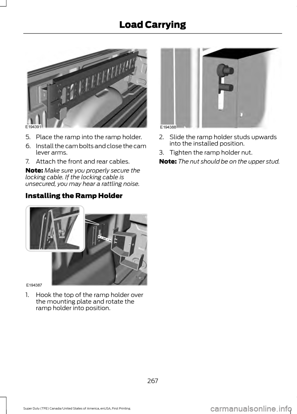
5. Place the ramp into the ramp holder.
6.
Install the cam bolts and close the cam
lever arms.
7. Attach the front and rear cables.
Note: Make sure you properly secure the
locking cable. If the locking cable is
unsecured, you may hear a rattling noise.
Installing the Ramp Holder 1. Hook the top of the ramp holder over
the mounting plate and rotate the
ramp holder into position. 2. Slide the ramp holder studs upwards
into the installed position.
3. Tighten the ramp holder nut.
Note: The nut should be on the upper stud.
267
Super Duty (TFE) Canada/United States of America, enUSA, First Printing Load CarryingE194391 E194387 E194388
Page 287 of 636
Once the trailer is level or slightly nose
down toward the vehicle:
•
Lock the bar tension adjuster in place.
• Check that the trailer tongue securely
attaches and locks onto the hitch.
• Install safety chains, lighting, and trailer
brake controls as required by law or the
trailer manufacturer.
Fifth-wheel Trailer Hitch (If Equipped)
Note: The mounting pads in the bed are
specifically designed for certain fifth-wheel
trailer hitches and gooseneck ball hitches.
Do not use these mounting pads for other
purposes.
Note: Contact an authorized dealer to
purchase gooseneck and fifth-wheel hitches
that are compatible with your vehicle.
Your vehicle may be equipped with a
fifth-wheel prep package. This package
enables your vehicle to accept certain
fifth-wheel trailer hitches and gooseneck
ball hitches. The fifth-wheel trailer hitch
attaches to the four mounting pads in the
pick-up bed. An optional 7-pin trailer wiring
connector may be in the bed as well. The
gooseneck ball hitch is a separate
mounting pad from the fifth-wheel hitch,
located in the center of the bed.
Shorter pick-up boxes, such as the 6½-foot
box on the F-250 and F-350, provide less
clearance between the cab and the
fifth-wheel and gooseneck trailer
compared to longer box pick-ups, such as
an 8-foot box on the F-250 or F-350. When
selecting a trailer and tow vehicle, it is
critical to check that this combination
provides clearance between the front of
the trailer and tow vehicle for turns up to
90 degrees. Failure to follow this recommendation could result in the trailer
contacting the cab of the tow vehicle
during tight turns that are typical during
low-speed parking and turning maneuvers.
This contact could result in damage to the
trailer and tow vehicle.
Safety Chains
Note:
Do not attach safety chains to the
bumper.
Always connect the safety chains to the
frame or hook retainers of your vehicle
hitch.
To connect the safety chains, cross the
chains under the trailer tongue and allow
enough slack for turning tight corners. Do
not allow the chains to drag on the ground.
Trailer Brakes WARNING
Do not connect a trailer's hydraulic
brake system directly to your
vehicle's brake system. Your vehicle
may not have enough braking power and
your chances of having a collision greatly
increase. Electric brakes and manual, automatic or
surge-type trailer brakes are safe if you
install them properly and adjust them to
the manufacturer's specifications. The
trailer brakes must meet local and federal
regulations.
The rating for the tow vehicle's braking
system operation is at the gross vehicle
weight rating, not the gross combined
weight rating.
Separate functioning brake systems
are required for safe control of towed
vehicles and trailers weighing more
than 1500 pounds (680 kilograms)
when loaded.
284
Super Duty (TFE) Canada/United States of America, enUSA, First Printing Towing
Page 294 of 636
•
Fuel economy may decrease with lower
temperatures during the first 8– 10
miles (12 –16 kilometers) of driving.
• Driving on flat terrain offers improved
fuel economy as compared to driving
on hilly terrain.
• Transmissions give their best fuel
economy when operated in the top
cruise gear and with steady pressure
on the gas pedal.
• Four-wheel-drive operation (if
equipped) is less fuel efficient than
two-wheel-drive operation.
• Close the windows for high-speed
driving.
DRIVING THROUGH WATER WARNING
Do not drive through flowing or deep
water as you may lose control of your
vehicle.
Note:
Driving through standing water can
cause vehicle damage.
Note: Engine damage can occur if water
enters the air filter.
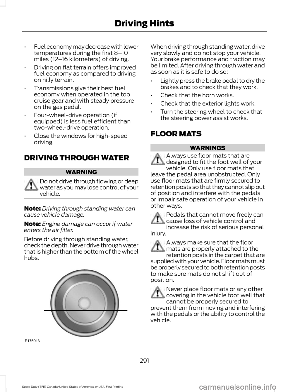
Before driving through standing water,
check the depth. Never drive through water
that is higher than the bottom of the wheel
hubs. When driving through standing water, drive
very slowly and do not stop your vehicle.
Your brake performance and traction may
be limited. After driving through water and
as soon as it is safe to do so:
•
Lightly press the brake pedal to dry the
brakes and to check that they work.
• Check that the horn works.
• Check that the exterior lights work.
• Turn the steering wheel to check that
the steering power assist works.
FLOOR MATS WARNINGS
Always use floor mats that are
designed to fit the foot well of your
vehicle. Only use floor mats that
leave the pedal area unobstructed. Only
use floor mats that are firmly secured to
retention posts so that they cannot slip out
of position and interfere with the pedals
or impair safe operation of your vehicle in
other ways. Pedals that cannot move freely can
cause loss of vehicle control and
increase the risk of serious personal
injury. Always make sure that the floor
mats are properly attached to the
retention posts in the carpet that are
supplied with your vehicle. Floor mats must
be properly secured to both retention posts
to make sure mats do not shift out of
position. Never place floor mats or any other
covering in the vehicle foot well that
cannot be properly secured to
prevent them from moving and interfering
with the pedals or the ability to control the
vehicle.
291
Super Duty (TFE) Canada/United States of America, enUSA, First Printing Driving HintsE176913