2017 FORD SUPER DUTY tire type
[x] Cancel search: tire typePage 384 of 636
Note:
Do not reduce tire pressure
to change the ride characteristics
of the vehicle. If you do not
maintain the inflation pressure at
the levels specified by Ford, your
vehicle may experience a condition
known as shimmy. Shimmy is a
severe vibration and oscillation in
the steering wheel after the vehicle
travels over a bump or dip in the
road that does not dampen out by
itself. Shimmy may result from
significant under-inflation of the
tires, improper tires (load range,
size, or type), or vehicle
modifications such as lift-kits. In
the event that your vehicle
experiences shimmy, you should
slowly reduce speed by either lifting
off the accelerator pedal or lightly
applying the brakes. The shimmy
will cease as the vehicle speed
decreases.
Maximum Inflation Pressure is
the tire manufacturer's maximum
permissible pressure and the
pressure at which the maximum
load can be carried by the tire. This
pressure is normally higher than
the manufacturer ’s recommended
cold inflation pressure which can
be found on the Safety
Compliance Certification Label
(affixed to either the door hinge
pillar, door-latch post, or the door
edge that meets the door-latch
post, next to the driver's seating
position), or Tire Label located on the B-pillar or the edge of the
driver's door. The cold inflation
pressure should never be set lower
than the recommended pressure
on the Safety Compliance
Certification Label or Tire Label.
When weather temperature
changes occur, tire inflation
pressures also change. A 10°F
(6°C) temperature drop can
cause a corresponding drop of 1
psi (7 kPa) in inflation pressure.
Check your tire pressures
frequently and adjust them to the
proper pressure which can be
found on the Safety Compliance
Certification Label or Tire Label.
To check the pressure in your
tire(s):
1. Make sure the tires are cool,
meaning they are not hot from
driving even a mile.
Note:
If you are checking tire
pressure when the tire is hot, (for
example, driven more than 1 mile
[1.6 kilometers]), never bleed or
reduce air pressure. The tires are
hot from driving and it is normal for
pressures to increase above
recommended cold pressures. A
hot tire at or below recommended
cold inflation pressure could be
significantly under-inflated.
381
Super Duty (TFE) Canada/United States of America, enUSA, First Printing Wheels and Tires
Page 385 of 636
Note:
If you have to drive a
distance to get air for your tire(s),
check and record the tire pressure
first and add the appropriate air
pressure when you get to the
pump. It is normal for tires to heat
up and the air pressure inside to go
up as you drive.
2. Remove the cap from the valve
on one tire, then firmly press the
tire gauge onto the valve and
measure the pressure.
3. Add enough air to reach the
recommended air pressure.
Note: If you overfill the tire, release
air by pressing on the metal stem
in the center of the valve. Then
recheck the pressure with your tire
gauge.
4. Replace the valve cap.
5. Repeat this procedure for each
tire, including the spare.
Note: Some spare tires operate at
a higher inflation pressure than the
other tires. For T type mini-spare
tires, (see the Dissimilar spare
wheel and tire assembly
information for a description. Store
and maintain at 60 psi (4.15 bar).
For full-size and dissimilar spare
tires, see the Dissimilar spare wheel
and tire assembly information for
a description. Store and maintain
at the higher of the front and rear
inflation pressure as shown on the
Safety Compliance Certification
Label or Tire Label. 6. Visually inspect the tires to
make sure there are no nails or
other objects embedded that
could poke a hole in the tire and
cause an air leak.
7. Check the sidewalls to make
sure there are no gouges, cuts or
bulges.
Tire Inflation Information
WARNING
An inflated tire and rim can
be very dangerous if
improperly used, serviced or
maintained. To reduce the risk of
serious injury, never attempt to
re-inflate a tire which has been run
flat or seriously under-inflated
without first removing the tire
from the wheel assembly for
inspection. Do not attempt to add
air to tires or replace tires or
wheels without first taking
precautions to protect persons
and property. All tires with Steel Carcass Plies
(if equipped):
This type of tire utilizes steel cords
in the sidewalls. As such, they
cannot be treated like normal light
truck tires. Tire service, including
adjusting tire pressure, must be
performed by personnel trained,
supervised and equipped
according to Federal Occupational
Safety and Health Administration
regulations. For example, during
382
Super Duty (TFE) Canada/United States of America, enUSA, First Printing Wheels and Tires
Page 388 of 636
WARNINGS
You should replace your
spare tire when you replace
the road tires or after six years due
to aging even if it has not been
used. U.S. DOT Tire Identification
Number
Both United States and Canada
Federal regulations require tire
manufacturers to place
standardized information on the
sidewall of all tires. This
information identifies and
describes the fundamental
characteristics of the tire and also
provides a U.S. DOT Tire
Identification Number for safety
standard certification and in case
of a recall.
This begins with the letters DOT
and indicates that the tire meets
all federal standards. The next
two numbers or letters are the
plant code designating where it
was manufactured, the next two
are the tire size code and the last
four numbers represent the week
and year the tire was built. For
example, the numbers 317 mean
the 31st week of 1997. After 2000
the numbers go to four digits. For
example, 2501 means the 25th
week of 2001. The numbers in
between are identification codes
used for traceability. This
information is used to contact
customers if a tire defect requires
a recall.
Tire Replacement
Requirements
Your vehicle is equipped with tires
designed to provide a safe ride
and handling capability.
WARNINGS
Only use replacement tires
and wheels that are the same
size, load index, speed rating and
type (such as P-metric versus
LT-metric or all-season versus
all-terrain) as those originally
provided by Ford. The
recommended tire and wheel size
may be found on either the Safety
Compliance Certification Label
(affixed to either the door hinge
pillar, door-latch post, or the door
edge that meets the door-latch
post, next to the driver ’s seating
position), or the Tire Label which
is located on the B-Pillar or edge
of the driver ’s door. If this
information is not found on these
labels, then you should contact
your authorized dealer as soon as
possible. Use of any tire or wheel
not recommended by Ford can
affect the safety and performance
of your vehicle, which could result
in an increased risk of loss of
vehicle control, vehicle rollover,
personal injury and death.
385
Super Duty (TFE) Canada/United States of America, enUSA, First Printing Wheels and Tires
Page 401 of 636
The trailer tire pressure monitoring system
can be reset through the menu in the
information display. See General
Information (page 111). Performing the
trailer setup process also resets the trailer
tire pressure monitoring system.
CHANGING A ROAD WHEEL WARNINGS
The use of tire sealant may damage
your tire pressure monitoring system
and should only be used in roadside
emergencies. If you must use a sealant, the
Ford Tire Mobility Kit sealant should be
used. The tire pressure monitoring system
sensor and valve stem on the wheel must
be replaced by an authorized dealer after
use of the sealant. If the tire pressure monitor sensor
becomes damaged, it will no longer
function. See
Tire Pressure
Monitoring System (page 390). Note:
If your vehicle is equipped with the
tire pressure monitoring system, the
indicator light will illuminate when the spare
tire is in use. To restore the full function of
the monitoring system, all road wheels
equipped with tire pressure monitoring
sensors must be mounted on the vehicle.
If you get a flat tire while driving, do not
apply the brake heavily. Instead, gradually
decrease your speed. Hold the steering
wheel firmly and slowly move to a safe
place on the side of the road. If your vehicle is equipped with the tire
pressure monitoring system, have a flat
serviced by an authorized dealer in order
to prevent damage to the system sensors.
See
Tire Pressure Monitoring System
(page 390). Replace the spare tire with a
road tire as soon as possible. During
repairing or replacing of the flat tire, have
the authorized dealer inspect the system
sensor for damage.
Dissimilar Spare Wheel and Tire
Assembly Information WARNING
Failure to follow these guidelines
could result in an increased risk of
loss of vehicle control, injury or death.
If you have a dissimilar spare wheel and
tire, then it is intended for temporary use
only. This means that if you need to use it,
you should replace it as soon as possible
with a road wheel and tire assembly that
is the same size and type as the road tires
and wheels that were originally provided
by Ford. If the dissimilar spare tire or wheel
is damaged, it should be replaced rather
than repaired.
A dissimilar spare wheel and tire assembly
is defined as a spare wheel and tire
assembly that is different in brand, size or
appearance from the road tires and wheels
and can be one of three types:
1.
T-type mini-spare:
This spare tire
begins with the letter T for tire size and
may have Temporary Use Only molded in
the sidewall.
2. Full-size dissimilar spare with label
on wheel:
This spare tire has a label on
the wheel that states: THIS WHEEL AND
TIRE ASSEMBLY FOR TEMPORARY USE
ONLY
When driving with one of the dissimilar
spare tires listed above, do not:
398
Super Duty (TFE) Canada/United States of America, enUSA, First Printing Wheels and Tires
Page 528 of 636
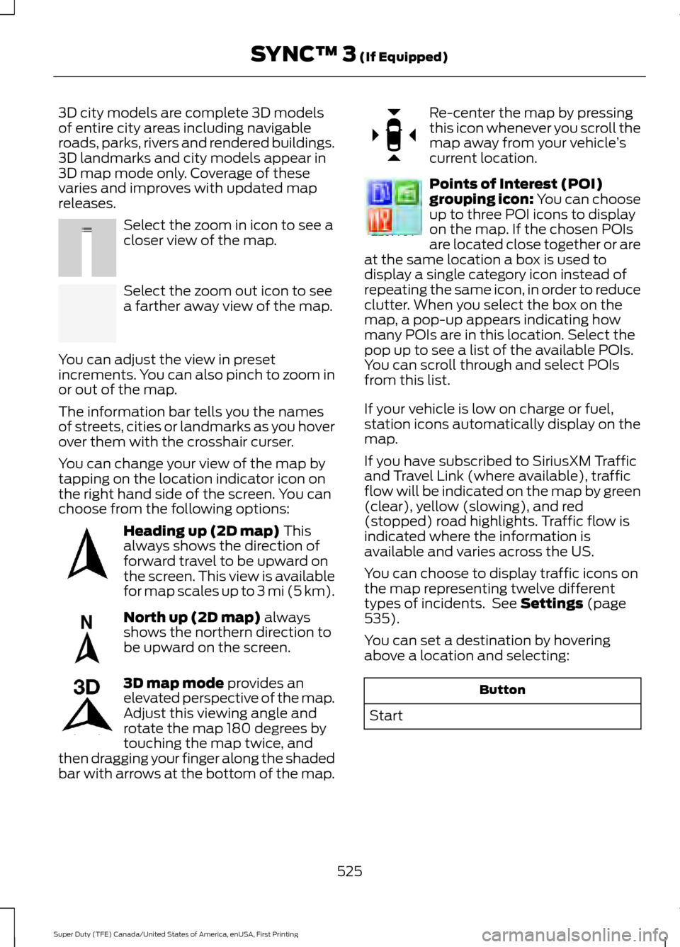
3D city models are complete 3D models
of entire city areas including navigable
roads, parks, rivers and rendered buildings.
3D landmarks and city models appear in
3D map mode only. Coverage of these
varies and improves with updated map
releases.
Select the zoom in icon to see a
closer view of the map.
Select the zoom out icon to see
a farther away view of the map.
You can adjust the view in preset
increments. You can also pinch to zoom in
or out of the map.
The information bar tells you the names
of streets, cities or landmarks as you hover
over them with the crosshair curser.
You can change your view of the map by
tapping on the location indicator icon on
the right hand side of the screen. You can
choose from the following options: Heading up (2D map) This
always shows the direction of
forward travel to be upward on
the screen. This view is available
for map scales up to
3 mi (5 km). North up (2D map)
always
shows the northern direction to
be upward on the screen. 3D map mode
provides an
elevated perspective of the map.
Adjust this viewing angle and
rotate the map 180 degrees by
touching the map twice, and
then dragging your finger along the shaded
bar with arrows at the bottom of the map. Re-center the map by pressing
this icon whenever you scroll the
map away from your vehicle
’s
current location. Points of Interest (POI)
grouping icon: You can choose
up to three POI icons to display
on the map. If the chosen POIs
are located close together or are
at the same location a box is used to
display a single category icon instead of
repeating the same icon, in order to reduce
clutter. When you select the box on the
map, a pop-up appears indicating how
many POIs are in this location. Select the
pop up to see a list of the available POIs.
You can scroll through and select POIs
from this list.
If your vehicle is low on charge or fuel,
station icons automatically display on the
map.
If you have subscribed to SiriusXM Traffic
and Travel Link (where available), traffic
flow will be indicated on the map by green
(clear), yellow (slowing), and red
(stopped) road highlights. Traffic flow is
indicated where the information is
available and varies across the US.
You can choose to display traffic icons on
the map representing twelve different
types of incidents. See
Settings (page
535).
You can set a destination by hovering
above a location and selecting: Button
Start
525
Super Duty (TFE) Canada/United States of America, enUSA, First Printing SYNC™ 3
(If Equipped)E207752 E207753 E207750 E207749 E207748 E207751 E207754
Page 625 of 636
Automatic Transmission Fluid
Check.............................................................337
Checking Automatic Transmission Fluid.................................................................... 337
Autowipers.......................................................84
Auxiliary Power Points...............................168 110 Volt - 400 Watt Capacity AC Power
Outlet................................................................. 168
12 Volt DC Power Point..................................... 168
Locations............................................................... 168
Auxiliary Switches
........................................561
For more information on the Upfitter
Interface Module and the auxiliary
switches, visit:................................................ 564
Upfitter Interface Module............................... 564
B
Battery See: Changing the 12V Battery..................... 343
Bed Extender
....................................................72
Grocery mode........................................................ 73
Tailgate mode........................................................ 72
Bed Ramps
....................................................265
Installing the Ramp Holder............................ 267
Stowing the Bed Ramp................................... 266
Using the Bed Ramp........................................ 265
Blind Spot Information System.............249 Blind Spot Information System with Trailer
Tow...................................................................... 251
Switching the System Off and On...............253
System Errors...................................................... 253
Using the System.............................................. 250
Bonnet Lock See: Opening and Closing the Hood..........320
Booster Seats..................................................30 Types of Booster Seats...................................... 30
Brake Fluid Check
.......................................340
Brakes................................................................221 General Information........................................... 221
Breaking-In....................................................290
Bulb Specification Chart
..........................350
C
Cabin Air Filter
.................................................151
California Proposition 65.............................12 Capacities and Specifications -
6.2L
.................................................................418
Specifications...................................................... 419
Capacities and Specifications - 6.7L Diesel............................................................428
Engine Oil Specifications................................ 433
Specifications..................................................... 430
Capacities and Specifications - 6.8L................................................................422
Specifications..................................................... 424
Capacities and Specifications
..................411
Car Wash See: Cleaning the Exterior............................... 361
Center Console
..............................................170
Changing a Bulb...........................................347 Cargo Lamp and Central High Mounted
Brake Lamp Bulbs........................................ 350
Fog Lamp Bulbs................................................. 348
Front Park and Direction Indicator Lamp Bulbs.................................................................. 347
Headlamp Bulbs................................................ 348
License Plate Lamp Bulb............................... 350
Rear Lamps, Brake Lamps, Rear Direction Indicator and Reversing Lamp
Bulbs................................................................. 349
Changing a Fuse
...........................................318
Fuses....................................................................... 318
Changing a Road Wheel...........................398 Dissimilar Spare Wheel and Tire Assembly
Information..................................................... 398
Location of the Spare Tire and Tools........399
Removing the Spare Tire (With Spare Tire Carrier Only).................................................. 400
Tire Change Procedure.................................... 401
Changing the 12V Battery
.........................343
Battery Management System....................... 345
Changing the Coalescer Filter Element.........................................................327
Changing the Engine Air Filter - 6.2L/ 6.8L................................................................353
Changing the Engine Air Filter - 6.7L Diesel
.............................................................354
Air Filter Restriction Gauge............................ 355
Changing the Engine-Mounted and Diesel Fuel Conditioner Module Fuel
Filters - 6.7L Diesel
...................................356
Diesel Fuel Conditioner Module
Filter................................................................... 356
622
Super Duty (TFE) Canada/United States of America, enUSA, First Printing Index