2017 FIAT TIPO 5DOORS STATION WAGON ignition
[x] Cancel search: ignitionPage 127 of 264

IMPORTANT
50)The sensors must be clean of mud,
dirt, snow or ice in order for the system to
operate correctly. Be careful not to scratch
or damage the sensors while cleaning
them. Avoid using dry, rough or hard
cloths. The sensors should be washed
using clean water with the addition of car
shampoo if necessary. When using special
washing equipment such as high pressure
jets or steam cleaning, clean the sensors
very quickly keeping the jet more than
10 cm away.
51)Have interventions on the bumper in
the area of the sensors carried out only by
a Fiat Dealership. Interventions on the
bumper that are not carried out properly
may compromise the operation of the
parking sensors
52)Only have the bumpers repainted or
any retouches to the paintwork in the area
of the sensors carried out by a Fiat
Dealership. Incorrect paint application
could affect the operation of the parking
sensors.
REAR VIEW CAMERA
(where provided)
DESCRIPTION
The rear camera 1 fig. 130 is located on
the tailgate.
124)
53)
Camera activation/deactivation
Every time reverse is engaged, the
display fig. 131 shows the area around
the vehicle, as seen by the rear camera.The images are shown on the display
together with a warning message.
With the “Camera Delay” option active,
when engaging the reverse gear, the
image from the camera will continue to
be displayed for up to 10 seconds after
reverse is disengaged, unless vehicle
speed is higher than 13 km/h, or:
- that the gearbox lever is in neutral;
- the ignition device is in position STOP.
When the gear lever is no longer set to
reverse, a button for deactivating the
display of the image from the camera
appears on theUconnect™ 5"or7"
HDsystem display along with the
images behind the vehicle, if the
"Camera Delay" setting is active on the
Uconnect™ 5"or7" HDsystem.
NOTE The displayed image may look a
bit distorted.
130P2000016-000-000
13107186J0002EM
125
Page 132 of 264
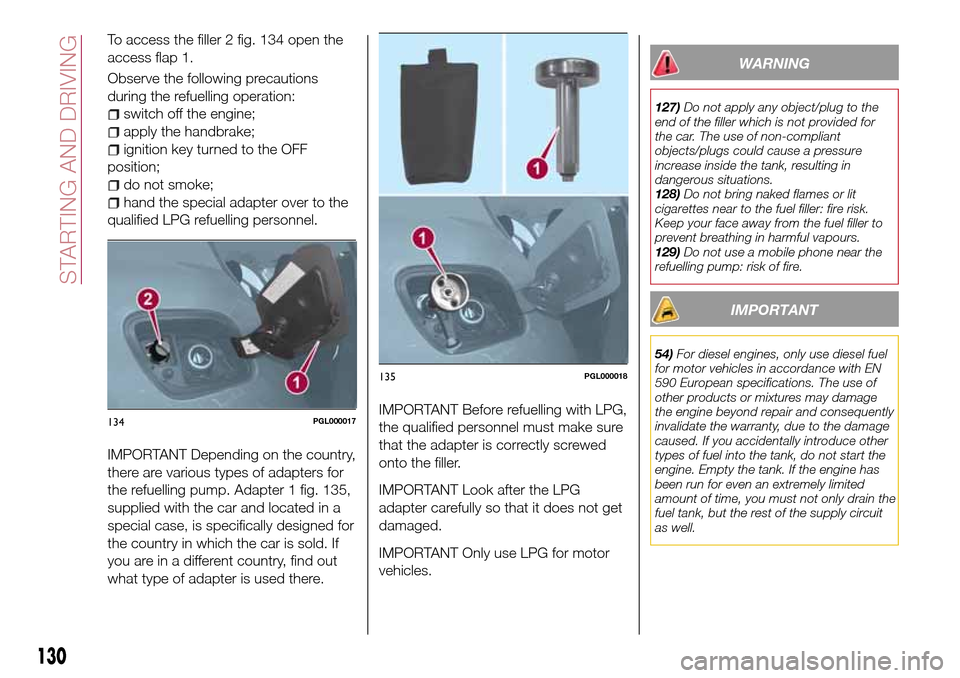
To access the filler 2 fig. 134 open the
access flap 1.
Observe the following precautions
during the refuelling operation:
switch off the engine;
apply the handbrake;
ignition key turned to the OFF
position;
do not smoke;
hand the special adapter over to the
qualified LPG refuelling personnel.
IMPORTANT Depending on the country,
there are various types of adapters for
the refuelling pump. Adapter 1 fig. 135,
supplied with the car and located in a
special case, is specifically designed for
the country in which the car is sold. If
you are in a different country, find out
what type of adapter is used there.IMPORTANT Before refuelling with LPG,
the qualified personnel must make sure
that the adapter is correctly screwed
onto the filler.
IMPORTANT Look after the LPG
adapter carefully so that it does not get
damaged.
IMPORTANT Only use LPG for motor
vehicles.
WARNING
127)Do not apply any object/plug to the
end of the filler which is not provided for
the car. The use of non-compliant
objects/plugs could cause a pressure
increase inside the tank, resulting in
dangerous situations.
128)Do not bring naked flames or lit
cigarettes near to the fuel filler: fire risk.
Keep your face away from the fuel filler to
prevent breathing in harmful vapours.
129)Do not use a mobile phone near the
refuelling pump: risk of fire.
IMPORTANT
54)For diesel engines, only use diesel fuel
for motor vehicles in accordance with EN
590 European specifications. The use of
other products or mixtures may damage
the engine beyond repair and consequently
invalidate the warranty, due to the damage
caused. If you accidentally introduce other
types of fuel into the tank, do not start the
engine. Empty the tank. If the engine has
been run for even an extremely limited
amount of time, you must not only drain the
fuel tank, but the rest of the supply circuit
as well.
134PGL000017
135PGL000018
130
STARTING AND DRIVING
Page 148 of 264

UNDER DASHBOARD CONTROL UNIT
fig. 166
USERSFUSE AMPERE
Front door unlocking (driver side) 1 7.5
Front door unlocking (passenger side) 2 7.5
Rear door unlocking (left) 3 7.5
Rear door unlocking (right) 4 7.5
LUGGAGE COMPARTMENT FUSE BOX
fig. 169
USERSFUSE AMPERE
Rear 12 V socket F97 15
Driver's front seat heater F99 10
Passenger side front seat heater F92 10
Driver's front seat lumbar adjustment F90 10
WARNING
134)If the replaced fuse blows again, contact a Fiat Dealership.
135)Never replace a fuse with another with a higher amp rating; DANGER OF FIRE
136)If a fuse NOT indicated in this or the previous page is used, contact a Fiat Dealership.
137)Before replacing a fuse, make sure that the ignition device is at STOP, that the key, if mechanical, has been removed and that all devices
are switched off and/or disconnected.
146
IN AN EMERGENCY
Page 155 of 264

The Fix&Go Automatic kit also includes:
one tank 1 fig. 187 containing the
sealing fluid, provided with: filler tube
2 and adhesive label 3 with the writing
"Max. 80 km/h”, to be attached in a
position easily visible to the driver (eg.
on the dashboard) after repairing the
tyre;
compressor 4 complete with
pressure gauge and connectors;
an instruction leaflet, to refer to for
prompt and correct use and that must
be then given to the personnel dealing
with the tyre treated with sealant;
a pair of gloves located in the side
compartment of the compressor;
some adaptors, for inflating different
elements.
TYRE REPAIRING AND
PRESSURE RESTORING
PROCEDURE
143)
60) 61)
Proceed as follows:
place the vehicle in a safe and
suitable area, engaging the parking
brake. Take the kit from the specific
compartment. Remove the adhesive
label of speed 3 fig. 187 and apply it in
a visible position. Wear the protective
gloves provided. Remove the cap from
the valve of the punctured tyre and
connect and firmly tighten the
transparent tube of the sealing fluid 1
fig. 188;
ensure that the on-off button 1
fig. 189 is in0(OFF) position. If
provided, open the cover of the
compressor 4 fig. 187 and insert the
electrical connector in the car’s 12V
socket fig. 190, start the car engine;
activate the compressor moving
on-off 1 button toI(ON) position
fig. 189. When the pressure gauge
2 shows the car’s required pressure
(see section “Wheels” under “Technical
data” chapter), switch off the
compressor moving on-off button 1 to
0position. If after 5 minutes from the
compressor ignition, the pressure
gauge 2 indicates a pressure less than
1.8 bar / 26 psi, switch off the
compressor, disconnect the sealing
fluid tube from the tyre valve, re-screw
the valve cap and move the car about
10 meters to allow the distribution of
sealing fluid in the tyre. Stop the car
186PGL000026
18708056J0003EM
18808056J0004EM
153
Page 156 of 264
safely and repeat the operation above
until the required pressure is reached. If
after other 5 min. from the compressor
ignition, the pressure gauge 2 still
indicates a pressure lower than 1.8 bar
/ 26 psi, the TYRE IS TOO DAMAGED
AND CANNOT BE REPAIRED. Remove
and place the kit in the specific
compartment and contact a Fiat
Dealership;if the required pressure is reached,
restart driving. Do not exceed 80 km/h.
Avoid sudden acceleration or braking.
After driving for about 8 km / 5 miles,
place the vehicle in a safe and suitable
area, engaging the parking brake. Pick
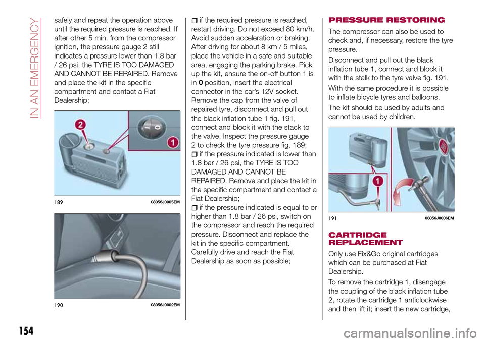
up the kit, ensure the on-off button 1 is
in0position, insert the electrical
connector in the car’s 12V socket.
Remove the cap from the valve of
repaired tyre, disconnect and pull out
the black inflation tube 1 fig. 191,
connect and block it with the stack to
the valve. Inspect the pressure gauge
2 to check the tyre pressure fig. 189;
if the pressure indicated is lower than
1.8 bar / 26 psi, the TYRE IS TOO
DAMAGED AND CANNOT BE
REPAIRED. Remove and place the kit in
the specific compartment and contact a
Fiat Dealership;
if the pressure indicated is equal to or
higher than 1.8 bar / 26 psi, switch on
the compressor and reach the required
pressure. Disconnect and replace the
kit in the specific compartment.
Carefully drive and reach the Fiat
Dealership as soon as possible;
PRESSURE RESTORING
The compressor can also be used to
check and, if necessary, restore the tyre
pressure.
Disconnect and pull out the black
inflation tube 1, connect and block it
with the stalk to the tyre valve fig. 191.
With the same procedure it is possible
to inflate bicycle tyres and balloons.
The kit should be used by adults and
cannot be used by children.
CARTRIDGE
REPLACEMENT
Only use Fix&Go original cartridges
which can be purchased at Fiat
Dealership.
To remove the cartridge 1, disengage
the coupling of the black inflation tube
2, rotate the cartridge 1 anticlockwise
and then lift it; insert the new cartridge,
18908056J0005EM
19008056J0002EM
19108056J0006EM
154
IN AN EMERGENCY
Page 158 of 264
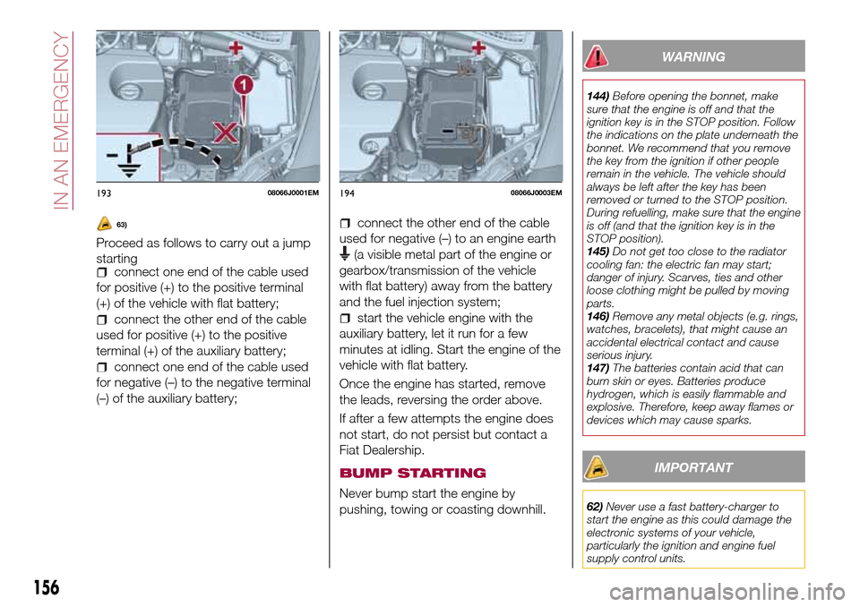
63)
Proceed as follows to carry out a jump
starting
connect one end of the cable used
for positive (+) to the positive terminal
(+) of the vehicle with flat battery;
connect the other end of the cable
used for positive (+) to the positive
terminal (+) of the auxiliary battery;
connect one end of the cable used
for negative (–) to the negative terminal
(–) of the auxiliary battery;
connect the other end of the cable
used for negative (–) to an engine earth
(a visible metal part of the engine or
gearbox/transmission of the vehicle
with flat battery) away from the battery
and the fuel injection system;
start the vehicle engine with the
auxiliary battery, let it run for a few
minutes at idling. Start the engine of the
vehicle with flat battery.
Once the engine has started, remove
the leads, reversing the order above.
If after a few attempts the engine does
not start, do not persist but contact a
Fiat Dealership.
BUMP STARTING
Never bump start the engine by
pushing, towing or coasting downhill.
WARNING
144)Before opening the bonnet, make
sure that the engine is off and that the
ignition key is in the STOP position. Follow
the indications on the plate underneath the
bonnet. We recommend that you remove
the key from the ignition if other people
remain in the vehicle. The vehicle should
always be left after the key has been
removed or turned to the STOP position.
During refuelling, make sure that the engine
is off (and that the ignition key is in the
STOP position).
145)Do not get too close to the radiator
cooling fan: the electric fan may start;
danger of injury. Scarves, ties and other
loose clothing might be pulled by moving
parts.
146)Remove any metal objects (e.g. rings,
watches, bracelets), that might cause an
accidental electrical contact and cause
serious injury.
147)The batteries contain acid that can
burn skin or eyes. Batteries produce
hydrogen, which is easily flammable and
explosive. Therefore, keep away flames or
devices which may cause sparks.
IMPORTANT
62)Never use a fast battery-charger to
start the engine as this could damage the
electronic systems of your vehicle,
particularly the ignition and engine fuel
supply control units.
19308066J0001EM19408066J0003EM
156
IN AN EMERGENCY
Page 159 of 264
63)Do not connect the cable to the
negative terminal (–) of the flat battery. The
following spark could lead to battery
explosion and cause serious harm. Only
use the specific earth point; do not use any
other exposed metallic part.FUEL CUT-OFF
SYSTEM
DESCRIPTION
Diesel and petrol versions
This intervenes in the case of an impact
causing:
the interruption of the fuel supply
with the engine consequently switching
off;
the automatic unlocking of the
doors;
turning on of the lights inside the
vehicle;
deactivation of climate control
system ventilation;
switching on of the hazard warning
lights (to deactivate the lights press the
button on the dashboard).
On some versions, the intervention of
the system is indicated by a message
shown on the display. In the same way,
a dedicated message on the display
warns the driver if system operation is
compromised.
IMPORTANT Carefully check the vehicle
for fuel leaks, for instance in the engine
compartment, under the vehicle or near
the tank area. After a collision, bring the
ignition device to STOP to prevent the
battery from running down.
LPG versions
On LPG versions, in addition to the
above, the fuel cut-off system stops
petrol supply immediately, closes the
LPG safety solenoid valve and stops
injection, consequently shutting off the
engine.
157
Page 160 of 264
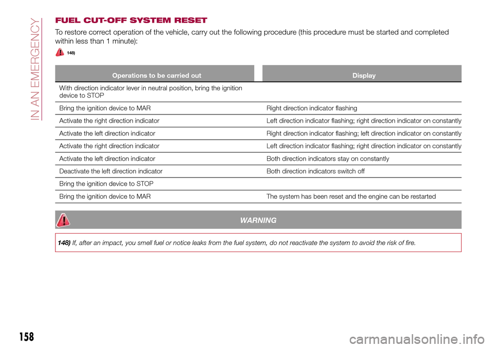
FUEL CUT-OFF SYSTEM RESET
To restore correct operation of the vehicle, carry out the following procedure (this procedure must be started and completed
within less than 1 minute):
148)
Operations to be carried out Display
With direction indicator lever in neutral position, bring the ignition
device to STOP
Bring the ignition device to MAR Right direction indicator flashing
Activate the right direction indicator Left direction indicator flashing; right direction indicator on constantly
Activate the left direction indicator Right direction indicator flashing; left direction indicator on constantly
Activate the right direction indicator Left direction indicator flashing; right direction indicator on constantly
Activate the left direction indicator Both direction indicators stay on constantly
Deactivate the left direction indicator Both direction indicators switch off
Bring the ignition device to STOP
Bring the ignition device to MAR The system has been reset and the engine can be restarted
WARNING
148)If, after an impact, you smell fuel or notice leaks from the fuel system, do not reactivate the system to avoid the risk of fire.
158
IN AN EMERGENCY