2017 FIAT TIPO 4DOORS Headlight
[x] Cancel search: HeadlightPage 63 of 240

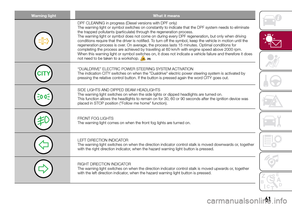
Warning light What it means
DPF CLEANING in progress (Diesel versions with DPF only)
The warning light or symbol switches on constantly to indicate that the DPF system needs to eliminate
the trapped pollutants (particulate) through the regeneration process.
The warning light or symbol does not come on during every DPF regeneration, but only when driving
conditions require that the driver is notified. To turn off the symbol, keep the vehicle in motion until the
regeneration process is over. On average, the process lasts 15 minutes. Optimal conditions for
completing the process are achieved by travelling at 60 km/h with engine speed above 2000 rpm.
When this warning light or symbol switches on, it does not indicate a vehicle failure and therefore it does
not need to be taken to a workshop.
24)
“DUALDRIVE” ELECTRIC POWER STEERING SYSTEM ACTIVATION
The indication CITY switches on when the "Dualdrive" electric power steering system is activated by
pressing the relative control button. If the button is pressed again the word CITY goes out.
SIDE LIGHTS AND DIPPED BEAM HEADLIGHTS
The warning light switches on when the side lights or dipped headlights are turned on.
This function allows the headlights to remain on for 30, 60 or 90 seconds after the ignition device was
placed in STOP position ("Follow me home" function).
FRONT FOG LIGHTS
The warning light comes on when the front fog lights are turned on.
LEFT DIRECTION INDICATOR
The warning light switches on when the direction indicator control stalk is moved downwards or, together
with the right direction indicator, when the hazard warning light button is pressed.
RIGHT DIRECTION INDICATOR
The warning light switches on when the direction indicator control stalk is moved upwards or, together
with the left direction indicator, when the hazard warning light button is pressed.
61
Page 64 of 240

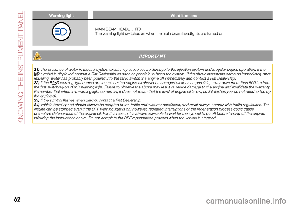
Warning light What it means
MAIN BEAM HEADLIGHTS
The warning light switches on when the main beam headlights are turned on.
IMPORTANT
21)The presence of water in the fuel system circuit may cause severe damage to the injection system and irregular engine operation. If thesymbol is displayed contact a Fiat Dealership as soon as possible to bleed the system. If the above indications come on immediately after
refuelling, water has probably been poured into the tank: switch the engine off immediately and contact a Fiat Dealership.
22)If the
warning light comes on, the exhausted engine oil should be changed as soon as possible, never drive more than 500 km from
the first switching-on of this warning light. Failure to observe the above may result in severe damage to the engine and invalidate the warranty.
Remember that when this warning light comes on, it does not mean that the level of engine oil is low, so if it flashes you do not need to top up
the engine oil.
23)If the symbol flashes when driving, contact a Fiat Dealership.
24)Vehicle travel speed should always be adapted to the traffic and weather conditions, and must always comply with traffic regulations. The
engine can be stopped even if the DPF warning light is on: however, repeated interruptions of the regeneration process could cause
premature deterioration of the engine oil. For this reason it is always advisable to wait for the symbol to go off before turning off the engine,
following the instructions above. Do not complete the DPF regeneration process when the vehicle is stopped.
62
KNOWING THE INSTRUMENT PANEL
Page 68 of 240

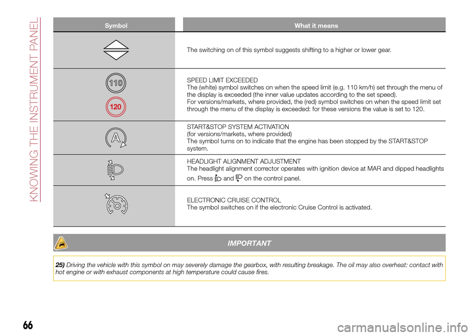
Symbol What it means
The switching on of this symbol suggests shifting to a higher or lower gear.
SPEED LIMIT EXCEEDED
The (white) symbol switches on when the speed limit (e.g. 110 km/h) set through the menu of
the display is exceeded (the inner value updates according to the set speed).
For versions/markets, where provided, the (red) symbol switches on when the speed limit set
through the menu of the display is exceeded: for these versions the value is set to 120.
START&STOP SYSTEM ACTIVATION
(for versions/markets, where provided)
The symbol turns on to indicate that the engine has been stopped by the START&STOP
system.
HEADLIGHT ALIGNMENT ADJUSTMENT
The headlight alignment corrector operates with ignition device at MAR and dipped headlights
on. Press
andon the control panel.
ELECTRONIC CRUISE CONTROL
The symbol switches on if the electronic Cruise Control is activated.
IMPORTANT
25)Driving the vehicle with this symbol on may severely damage the gearbox, with resulting breakage. The oil may also overheat: contact with
hot engine or with exhaust components at high temperature could cause fires.
66
KNOWING THE INSTRUMENT PANEL
Page 79 of 240

Under special conditions (e.g. vehicle
loaded asymmetrically on one side,
towing a trailer, damaged or worn tyre,
fitting the space-saver wheel, use of the
"Fix&Go Automatic" tyre repair kit, fitting
snow chains, fitting different tyres on
the axles) the system may provide false
indications or be temporarily
deactivated.
If the system is temporarily deactivated
the
warning light flashes for about
75 seconds and then is continuously
on; at the same time, the display shows
a warning message.
This indication is displayed also after
the engine has been switched off and
then on again if the correct operating
conditions are not restored.
In the case of abnormal signals, it is
recommended to perform the RESET
procedure. If the signals reappear once
the RESET procedure has started,
check that the type of tyres used are
the same on all four wheels and that the
tyres are not damaged; if the
space-saver wheel is being used, refit
the wheel with a tire with normal
dimensions instead of the space-saver
wheel as soon as possible; if possible
remove the snow chains; make sure
that the load is distributed correctly and
repeat the RESET procedure, driving on
a clean and surfaced road. If the signals
persist, contact a Fiat Dealership.
WARNING
60)The system is an aid for the driver, who
must always pay full attention while driving.
The responsibility always rests with the
driver, who must take into account the
traffic conditions in order to drive in
complete safety. The driver must always
maintain a safe distance from the vehicle in
front.
61)If the driver depresses the brake pedal
fully or carries out a fast steering during
system operation, the automatic braking
function may stop (e.g. to allow a possible
manoeuvre to avoid the obstacle).
62)The system intervenes on vehicles
travelling in the same lane. People, animals
and things (e.g. pushchairs) are not taken
into consideration.
63)If the car must be placed on a roller
bench for maintenance interventions or if it
is washed in an automatic roller washing
tunnel with an obstacle in the front part
(e.g. another car, a wall or another
obstacle), the system may detect its
presence and activate. In this case the
system must be deactivated through the
settings of the5”Uconnect™system.
64)If the iTMPS system signals a pressure
decrease on the tyres, it is recommended
to check the pressure on all four tyres.
65)The iTPMS does not relieve the driver
from the obligation to check the tyre
pressure every month; it is not even to be
considered a replacing system for
maintenance or a safety system.66)Tyre pressure must be checked with
tyres cold. Should it become necessary for
whatever reason to check pressure with
warm tyres, do not reduce pressure even
though it is higher than the prescribed
value, but repeat the check when tyres are
cold
67)The iTPMS cannot indicate sudden tyre
pressure drops (e.g. if a tyre bursts). In this
case, stop the vehicle, braking with caution
and avoiding abrupt steering.
68)The system only warns that the tyre
pressure is low: it is not able to inflate
them.
69)Insufficient tyre inflation increases fuel
consumption, reduces the tread duration
and may affect the capacity to drive safely.
IMPORTANT
26)The system may have limited or absent
operation due to weather conditions such
as: heavy rain, hail, thick fog, heavy snow.
27)The section of the bumper before the
sensor must not be covered with
adhesives, auxiliary headlights or any other
object.
28)System intervention might be
unexpected or delayed when other vehicles
transport loads projecting from the side,
above or from the rear, with respect to the
normal size of the vehicle.
29)Operation can be adversely affected by
any structural change made to the vehicle,
such as a modification to the front
geometry, tyre change, or a heavier load
than the standard load of the vehicle.
77
Page 123 of 240

HAZARD WARNING
LIGHTS
CONTROL
Press the fig. 110 button to switch the
lights on/off.
When the hazard warning lights are on,
the
andwarning lights flash.
IMPORTANT The use of hazard warning
lights is governed by the highway code
of the country you are driving in:
comply with legal requirements.
Emergency braking
In the event of emergency braking the
hazard warning lights switch on
automatically as well as warning lights
andin the instrument panel.
The lights switch off automatically when
emergency braking ceases.
BULB
REPLACEMENT
127) 128) 129)
49)
GENERAL
INSTRUCTIONS
Before replacing a bulb check the
contacts for oxidation;
replace blown bulbs with others of
the same type and power;
after replacing a headlight bulb,
always check its alignment;
when a light is not working, check
that the corresponding fuse is intact
before changing the bulb. For the
location of fuses, refer to the paragraph
"If a fuse blows" in this chapter.
IMPORTANT When the weather is cold
or damp or after heavy rain or washing,
the surface of headlights or rear lights
may steam up and/or form drops of
condensation on the inside. This is a
natural phenomenon due to the
difference in temperature and humidity
between the inside and the outside of
the glass which does not indicate a
fault and does not compromise the
normal operation of lighting devices.
The mist disappears quickly when the
lights are turned on, starting from the
centre of the diffuser, extending
progressively towards the edges.
11008016J0001EM
121
Page 125 of 240

Light bulbs Type Power Figure reference
Front side lights/Daytime running lights (DRL) H15 15W 4
Main beam headlights (halogen) H15 55 W 4
Dipped headlights H7 55 W 3
Front direction indicators PY21W 21 W 2
Number plate W5W 5 W 1
Rear side/brake light P21W 21 W 2
Rear direction indicators WY16W 16 W 1
Reversing light W16W 16 W 1
3rd stop W5W 5 W 1
Fog lights H11 55 W 4
Rear fog light W16W 16 W 1
Front ceiling light C5W 5 W 1
Front roof lights (sun visors) C5W 5 W 1
Rear ceiling light C5W 6W 1
Luggage compartment light W5W 5 W 1
Glove compartment light W5W 5 W 1
123
Page 126 of 240

REPLACING AN
EXTERNAL BULB
Front bulb position
1. Dipped beam headlights
2. Fog lights
3. Main beam headlights/Daytime
running lights (DRL)
4. Direction indicator.Main beam headlights/Daytime
running lights (DRL)
To replace the bulb 3 fig. 111, proceed
as follows:
working from inside the engine
compartment, remove rubber cap 1
fig. 112;
rotate the bulb-bulb holder assembly
anticlockwise and extract it;
disconnect the electrical connector
and replace the bulb-bulb holder
assembly 2;
reconnect the electrical connector to
the new assembly;
then insert the assembly in its
housing and turn it clockwise, making
sure that it is locked correctly;
refit the rubber cap 1.
IMPORTANT Only replace the bulb
when the engine is off. Also ensure that
the engine is cold, to prevent the risk of
burns.
Dipped headlights
Right headlight
To replace the bulb 1 fig. 111, proceed
as follows:
steer the vehicle wheels completely
inwards;
undo screw 1 fig. 113 using the
screwdriver provided and remove
inspection flap 2;
remove the rubber plug
disconnect the electrical connector;
extract the bulb, releasing it from the
retaining springs;
replace the new bulb and carry out
the procedure described previously in
reverse.
11108026J0002EM
11208026J0025EM
113P08026J004
124
IN AN EMERGENCY
Page 127 of 240

Left headlight
working from inside the engine
compartment, remove the rubber cap
from the dipped beam headlight bulb 1
fig. 111;
extract the bulb, releasing it from the
retaining springs;
disconnect the electrical connector
and replace the bulb 1 fig. 111;
reconnect the electrical connector to
the new bulb;
reposition the assembly in the seat;
refit the rubber cap.
IMPORTANT Only replace the bulb
when the engine is off. Also ensure that
the engine is cold, to prevent the risk of
burns.
Front direction indicators
To replace the bulb 4 fig. 111, proceed
as follows:
using the screwdriver provided with
the car, remove the indicated fasteners
and remove the cover 1 fig. 114;
rotate the bulb-bulb holder assembly
anticlockwise;
replace the "bayonet-fitted" bulb;
then insert the bulb-bulb holder
assembly in its housing and turn it
clockwise, making sure that it is locked
correctly;
refit the cover and block it by placing
the fasteners back in position.Front fog lights
To replace the bulbs, proceed as
follows:
steer the vehicle wheels completely
inwards;
undo screw 1 fig. 115 using the
screwdriver provided and remove
inspection flap 2;
11408026J0011EM
115P08026J0012
11608026J0016EM
125