Page 169 of 350
RADIO OPERATION AND MOBILE PHONES
Under certain conditions, the mobile phone being on in
your vehicle can cause erratic or noisy performance
from your radio. This condition may be lessened or
eliminated by relocating the mobile phone antenna.
This condition is not harmful to the radio. If your radio
performance does not satisfactorily “clear” by the repo-
sitioning of the antenna, it is recommended that the
radio volume be turned down or off during mobile
phone operation.
CLIMATE CONTROLS
Manual Climate Control Overview
Manual Climate Control
4
UNDERSTANDING YOUR INSTRUMENT PANEL 167
Page 170 of 350
Manual Climate Control Descriptions
IconDescription
A/C Button
Push the A/C button to engage the Air Conditioning (A/C). A LED will illuminate when
the A/C system is engaged.
Recirculation Setting
When this setting is on, the system between recirculation mode and outside air mode.
Recirculation can be used when outside conditions such as smoke, odors, dust, or high
humidity are present.
NOTE:
•Continuous use of the Recirculation mode may make the inside air stuffy and window
fogging may occur. Extended use of this mode is not recommended.
•The use of the Recirculation mode in cold or damp weather could cause windows to fog
on the inside, because of moisture buildup inside the vehicle. Select the outside air posi-
tion for maximum defogging.
•Recirculation can be used in all modes except for Defrost.
•The A/C can be deselected manually without disturbing the mode control selection.
168 UNDERSTANDING YOUR INSTRUMENT PANEL
Page 171 of 350

IconDescription
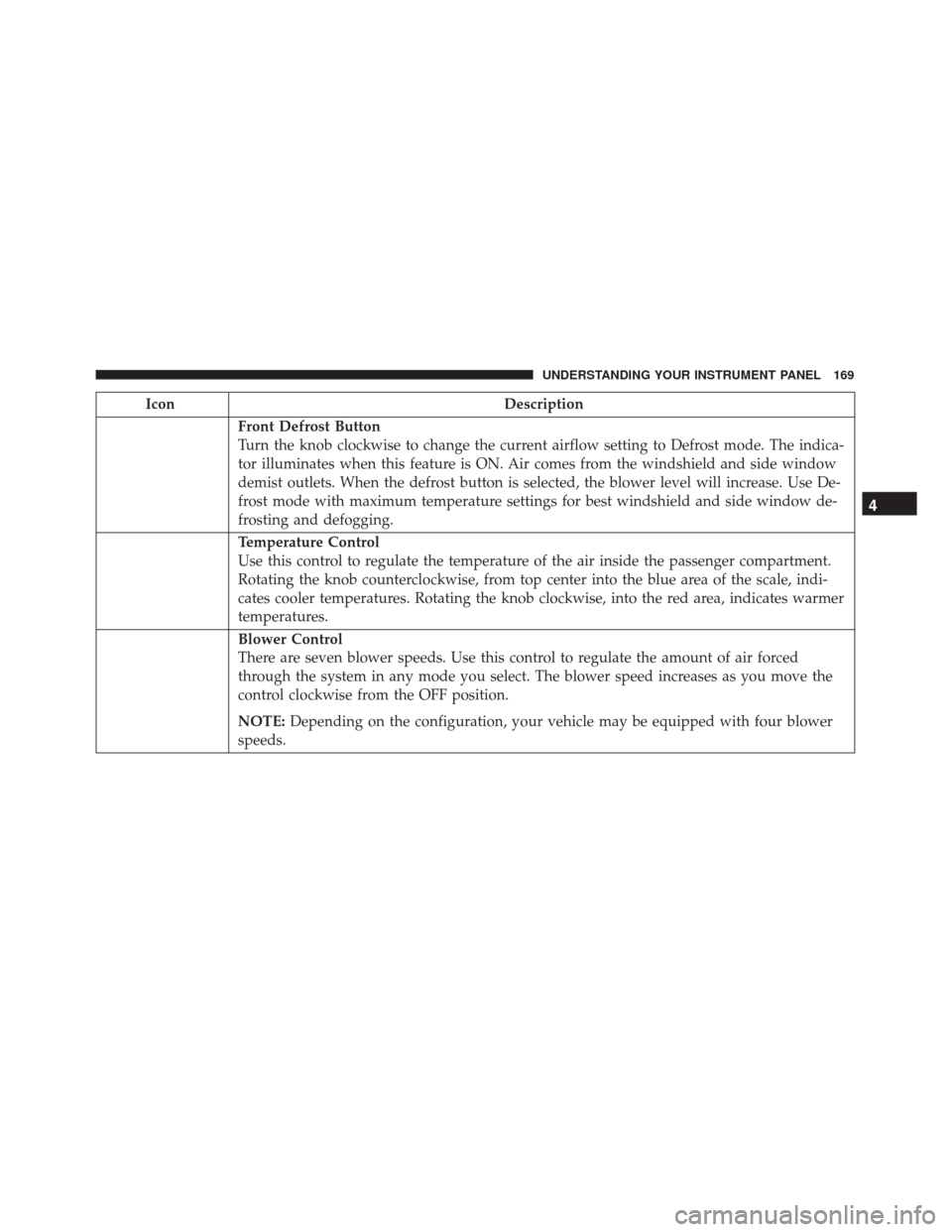
Front Defrost Button
Turn the knob clockwise to change the current airflow setting to Defrost mode. The indica-
tor illuminates when this feature is ON. Air comes from the windshield and side window
demist outlets. When the defrost button is selected, the blower level will increase. Use De-
frost mode with maximum temperature settings for best windshield and side window de-
frosting and defogging.
Temperature Control
Use this control to regulate the temperature of the air inside the passenger compartment.
Rotating the knob counterclockwise, from top center into the blue area of the scale, indi-
cates cooler temperatures. Rotating the knob clockwise, into the red area, indicates warmer
temperatures.
Blower Control
There are seven blower speeds. Use this control to regulate the amount of air forced
through the system in any mode you select. The blower speed increases as you move the
control clockwise from the OFF position.
NOTE:Depending on the configuration, your vehicle may be equipped with four blower
speeds.
4
UNDERSTANDING YOUR INSTRUMENT PANEL 169
Page 172 of 350

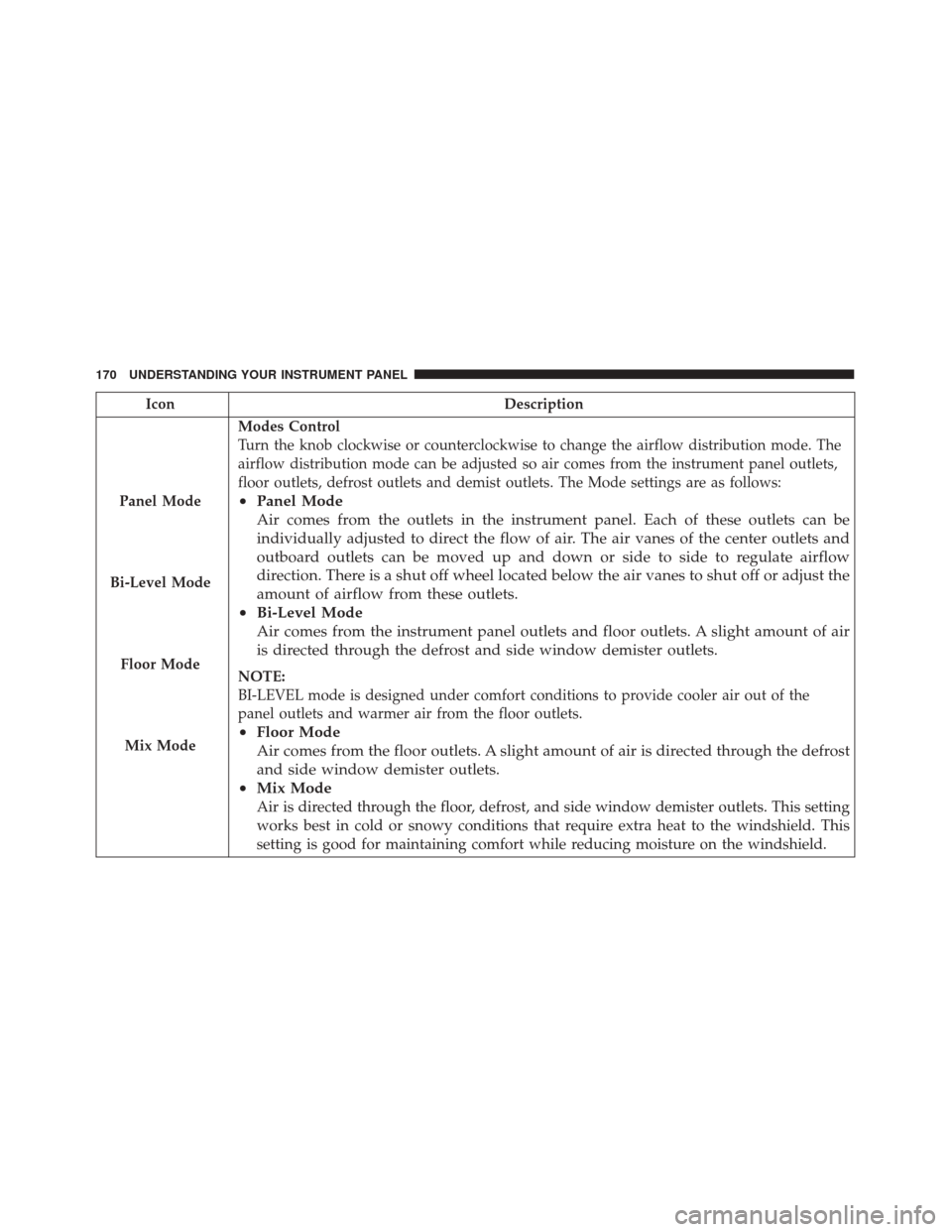
IconDescription
Panel Mode
Bi-Level Mode
Floor Mode
Mix Mode
Modes Control
Turn the knob clockwise or counterclockwise to change the airflow distribution mode. The
airflow distribution mode can be adjusted so air comes from the instrument panel outlets,
floor outlets, defrost outlets and demist outlets. The Mode settings are as follows:
• Panel Mode
Air comes from the outlets in the instrument panel. Each of these outlets can be
individually adjusted to direct the flow of air. The air vanes of the center outlets and
outboard outlets can be moved up and down or side to side to regulate airflow
direction. There is a shut off wheel located below the air vanes to shut off or adjust the
amount of airflow from these outlets.
• Bi-Level Mode
Air comes from the instrument panel outlets and floor outlets. A slight amount of air
is directed through the defrost and side window demister outlets.
NOTE:
BI-LEVEL mode is designed under comfort conditions to provide cooler air out of the
panel outlets and warmer air from the floor outlets.
•Floor Mode
Air comes from the floor outlets. A slight amount of air is directed through the defrost
and side window demister outlets.
• Mix Mode
Air is directed through the floor, defrost, and side window demister outlets. This setting
works best in cold or snowy conditions that require extra heat to the windshield. This
setting is good for maintaining comfort while reducing moisture on the windshield.
170 UNDERSTANDING YOUR INSTRUMENT PANEL
Page 173 of 350
CAUTION!
Failure to follow these cautions can cause damage
to the heating elements:
•Use care when washing the inside of the rear
window. Do not use abrasive window cleaners on
the interior surface of the window. Use a soft
cloth and a mild washing solution, wiping paral-
lel to the heating elements. Labels can be peeled
off after soaking with warm water.
• Do not use scrapers, sharp instruments, or abra-
sive window cleaners on the interior surface of
the window.
• Keep all objects a safe distance from the window.
Automatic Temperature Control Overview
Automatic Temperature Controls
4
UNDERSTANDING YOUR INSTRUMENT PANEL 171
Page 174 of 350

Control Descriptions
IconDescription
A/C Button
Push and release to change the current setting, the indicator illuminates when A/C is ON.
Performing this function again will cause the A/C operation to switch into manual mode
and the A/C indicator will turn off.
Recirculation Button
Push and release this button to change the system between recirculation mode and outside
air mode. Recirculation can be used when outside conditions such as smoke, odors, dust,
or high humidity are present.
NOTE:
•Continuous use of the Recirculation mode may make the inside air stuffy and window
fogging may occur. Extended use of this mode is not recommended.
•The use of the Recirculation mode in cold or damp weather could cause windows to fog
on the inside, because of moisture buildup inside the vehicle. Select the outside air posi-
tion for maximum defogging.
•Recirculation can be used in all modes except for Defrost.
•The A/C can be deselected manually without disturbing the mode control selection.
172 UNDERSTANDING YOUR INSTRUMENT PANEL
Page 175 of 350

IconDescription
AUTO Button — If Equipped
Automatically controls the interior cabin temperature by adjusting airflow distribution and
amount. Performing this function will cause the system to switch between manual mode
and automatic modes. Refer to “Automatic Operation” for more information.
Front Defrost Button
Push and release to change the current airflow setting to Defrost mode. The indicator illu-
minates when this feature is ON. Air comes from the windshield and side window demist
outlets. When the defrost button is selected, the blower level will increase. Use Defrost
mode with maximum temperature settings for best windshield and side window defrosting
and defogging. Performing this function will cause the ATC to switch into manual mode. If
the front defrost mode is turned off the climate system will return the previous setting.
Blower Control UP And DOWN Button
Provides the passenger with blower control. Push the UP button to increase blower speed.
Push the DOWNbutton to decrease blower speed
4
UNDERSTANDING YOUR INSTRUMENT PANEL 173
Page 176 of 350

IconDescription
Panel Mode
Floor Mode
Bi-Level Mode
Mix Mode
Modes Control
Push the button in the center of the knob to change the airflow distribution mode. The air-
flow distribution mode can be adjusted so air comes from the instrument panel outlets,
floor outlets, defrost outlets and demist outlets. The Mode settings are as follows:
• Panel Mode
Air comes from the outlets in the instrument panel. Each of these outlets can be
individually adjusted to direct the flow of air. The air vanes of the center outlets and
outboard outlets can be moved up and down or side to side to regulate airflow
direction. There is a shut off wheel located below the air vanes to shut off or adjust the
amount of airflow from these outlets.
• Floor Mode
Air comes from the floor outlets. A slight amount of air is directed through the defrost
and side window demister outlets.
• Bi-Level Mode
Air comes from the instrument panel outlets and floor outlets. A slight amount of air
is directed through the defrost and side window demister outlets. To access this mode,
press both the Panel and Floor Mode buttons
NOTE:
BI-LEVEL mode is designed under comfort conditions to provide cooler air out of the
panel outlets and warmer air from the floor outlets.
174 UNDERSTANDING YOUR INSTRUMENT PANEL