2017 FIAT 124 SPIDER steering
[x] Cancel search: steeringPage 191 of 300
7. Install the new bulb in the reverse
order of the removal procedure.
Headlights (high beam) with
Daytime Running Lights
(If Equipped with LED Lamps)
Proceed as follows:
1. If you are changing the right bulb,
start the engine, turn the steering wheel
all the way to the right, and turn off
engine. If you are changing the left bulb,
turn the steering wheel to the left.
2. Make sure the ignition is placed in
the OFF mode, and the headlight
switch is off.
3. Remove the fasteners in the seven
locations and partially peel back the
mud guard.
4. Turn the socket and bulb assembly
counterclockwise and remove it.
5. Turn the cover counterclockwise and
remove it, disconnect the connector
from the unit by pressing the tab on the
connector with your finger and pulling
the connector.
6. Turn the socket and bulb assembly
counterclockwise and remove it.
7. Disconnect the bulb from the
socket.
8. Install the new bulb in the reverse
order of the removal procedure.Front Direction Indicator Lights
Proceed as follows:
1. If you are changing the right bulb,
start the engine, turn the steering wheel
all the way to the right, and turn off
engine. If you are changing the left bulb,
turn the steering wheel to the left.
2. Make sure the ignition is switched
off, and the headlight switch is off.
3. Remove the fasteners in the five
locations and partially peel back the
mud guard.
4. Disconnect the connector from the
unit by pressing the tab on the
connector with your finger and pulling
the connector rearward.
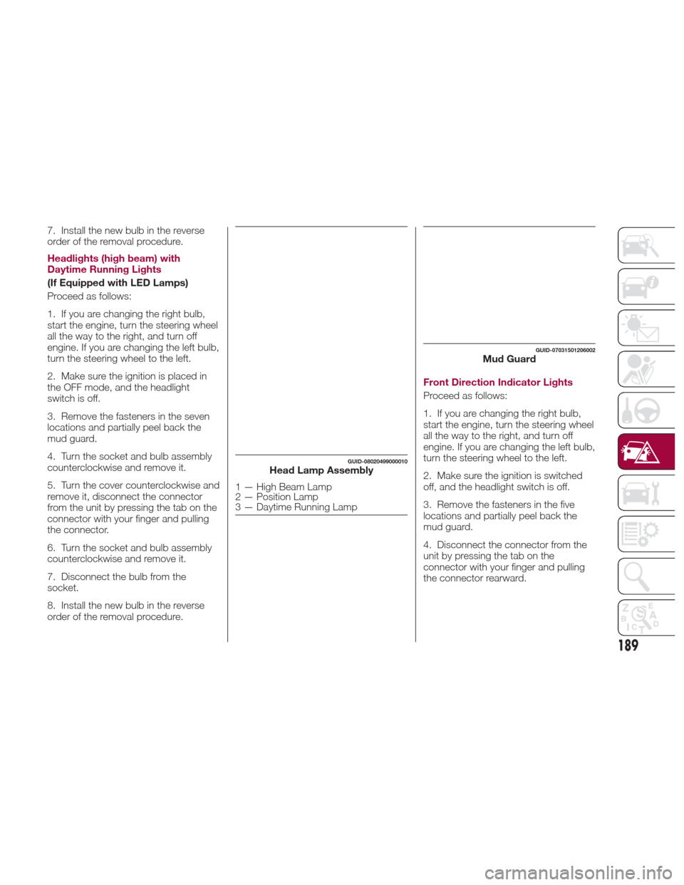
GUID-08020499000010Head Lamp Assembly
1 — High Beam Lamp
2 — Position Lamp
3 — Daytime Running Lamp
GUID-07031501206002Mud Guard
189
Page 192 of 300
5. Turn the socket and bulb assembly
counterclockwise and remove it.
6. Disconnect the bulb from the
socket.7. Install the new bulb in the reverse
order of the removal procedure.
Fog Lights
Proceed as follows:
1. If you are changing the right bulb,
start the engine, turn the steering wheel
all the way to the right, and turn off
engine. If you are changing the left bulb,
turn the steering wheel to the left.
2. Make sure the ignition is switched
off, and the headlight switch is off.
3. Remove the fasteners in the five
locations and partially peel back the
mud guard.
4. Disconnect the connector from the
unit by pressing the tab on the
connector with your finger and pulling
the connector.
5. Turn the socket and bulb assembly
counterclockwise, extract the bulb and
remove it;
6. Disconnect the bulb from the
socket.
7. Install the new bulb in the reverse
order of the removal procedure.Brake lights / Tail lights
Go to your authorized dealer when the
replacement of this lights is necessary.
Side Direction Indicator Lights
Proceed as follows:
1. Make sure the ignition is placed in
the OFF mode, and the headlight
switch is off.
2. If you are changing the right bulb,
start the engine, turn the steering wheel
all the way to the right, and turn off
engine. If you are changing the left bulb,
turn the steering wheel to the left.
3. Remove the fasteners in the five
locations and partially peel back the
mud guard.
4. Disconnect the electrical connector
from the bulb by pressing the tab on
the connector with your finger and
pulling the connector.
5. Remove the lens assembly by
pressing the tab on the unit with your
finger and pulling the unit forward to
compress in the internal catch, then pull
the cluster outwards.
6. Lift up the lens assembly, and then
remove the cluster and install the new
side direction indicator lens assembly in
the reverse order of the removal
procedure.
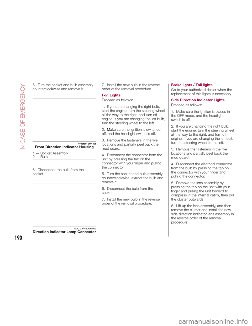
07031501-207-001Front Direction Indicator Housing
1 — Socket Assembly
2 — Bulb
GUID-07031501208002Direction Indicator Lamp Connector
190
IN CASE OF EMERGENCY
Page 198 of 300
REPLACING FUSES
General Information
Warning!
When replacing a blown fuse, always
use an appropriate replacement fuse with
the same amp rating as the original fuse.
Never replace a fuse with another fuse of
higher amp rating. Never replace a blown
fuse with metal wires or any other material.
Failure to use proper fuses may result in
serious personal injury, fire and/or property
damage.
Before replacing a fuse, make sure that
the ignition is off and that all the other
services are switched off and/or
disengaged.
If the replaced fuse blows again, contact
an authorized dealer.
If a general protection fuse for safety
systems (air bag system, braking system),
power unit systems (engine system,
gearbox system) or steering system blows,
contact an authorized dealer.
Your vehicle's electrical system is
protected by fuses.
If any lights, accessories, or controls do
not work, inspect the appropriate circuit
protector. If a fuse has blown, the inside
element will be melted. If the same fuse
blows again, go to an Authorized Dealer
as soon as possible.
Fuse location
Fuses are grouped together in two fuse
boxes located in the interior on the left
side of the vehicle and under the hood.
Interior Fuses
If the electrical system does not work,
first inspect the fuses on the vehicle's
left side.
Proceed as follows:
1. Make sure the ignition is placed in
the OFF mode, and other switches are
turned off.
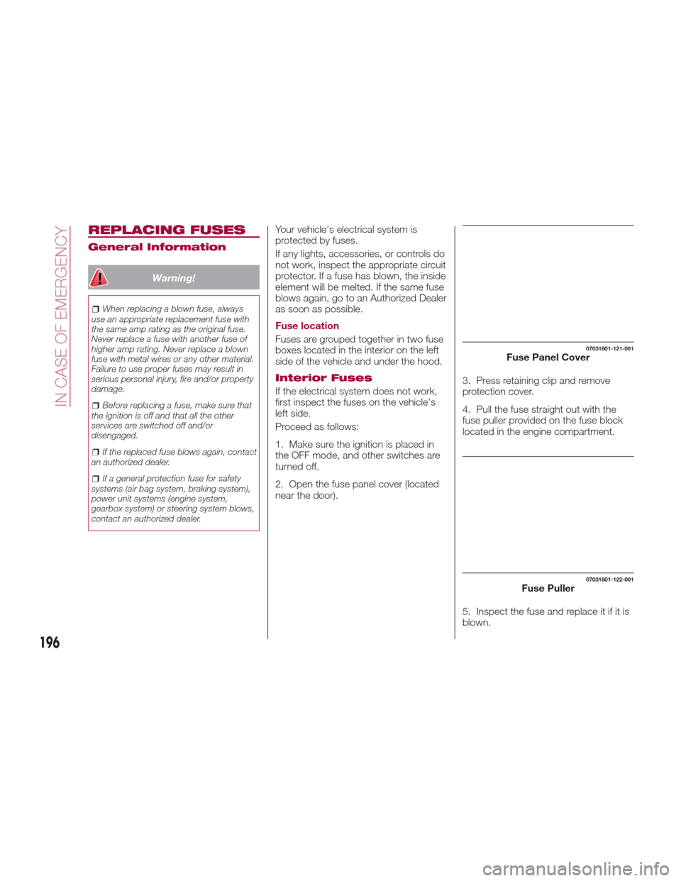
2. Open the fuse panel cover (located
near the door). 3. Press retaining clip and remove
protection cover.
4. Pull the fuse straight out with the
fuse puller provided on the fuse block
located in the engine compartment.
5. Inspect the fuse and replace it if it is
blown.
07031601-121-001Fuse Panel Cover
07031601-122-001Fuse Puller
196
IN CASE OF EMERGENCY
Page 202 of 300
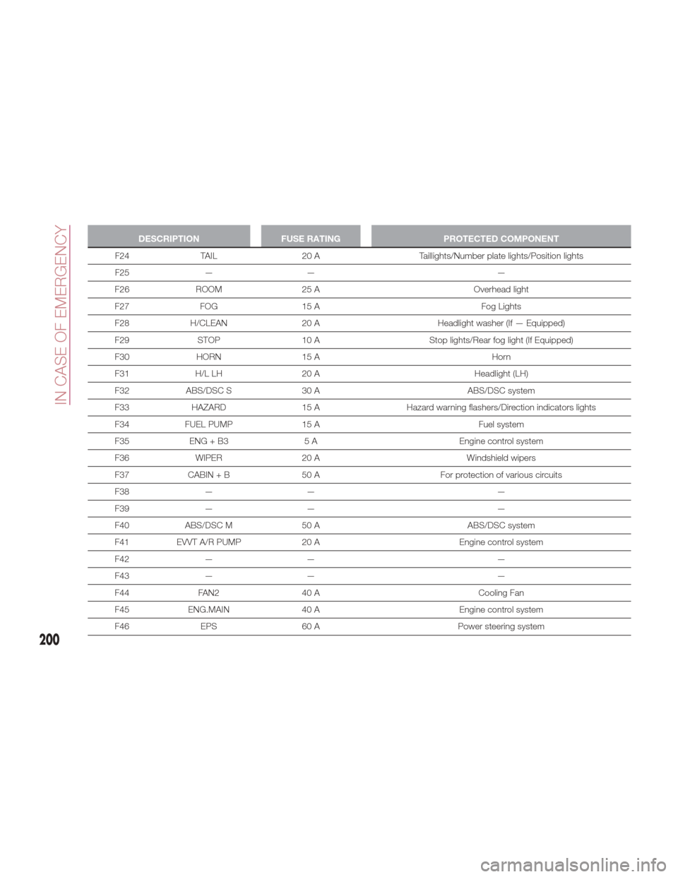
DESCRIPTIONFUSE RATING PROTECTED COMPONENT
F24 TAIL 20 A Taillights/Number plate lights/Position lights
F25
— — —
F26 ROOM 25 A Overhead light
F27 FOG 15 A Fog Lights
F28 H/CLEAN 20 A Headlight washer (If — Equipped)
F29 STOP 10 A Stop lights/Rear fog light (If Equipped)
F30 HORN 15 A Horn
F31 H/L LH 20 A Headlight (LH)
F32 ABS/DSC S 30 A ABS/DSC system
F33 HAZARD 15 AHazard warning flashers/Direction indicators lights
F34 FUEL PUMP 15 A Fuel system
F35 ENG + B3 5 A Engine control system
F36 WIPER 20 A Windshield wipers
F37 CABIN + B 50 A For protection of various circuits
F38 — — —
F39 — — —
F40 ABS/DSC M 50 A ABS/DSC system
F41 EVVT A/R PUMP 20 A Engine control system
F42 — — —
F43 — — —
F44 FAN2 40 A Cooling Fan
F45 ENG.MAIN 40 A Engine control system
F46 EPS 60 A Power steering system
200
IN CASE OF EMERGENCY
Page 215 of 300
Warning!
Never use the air compressor above
43.5 psi (3 Bar). Using the air compressor
at an inflation pressure above 3 Bar
(43.5 psi) continuously is dangerous. If the
air compressor overheats, hot air will be
exhausted and you could get burned.
Caution!
If the tire inflation pressure does not
increase, repair of the tire is not possible. If
the tire does not reach the specified tire
inflation pressure within 10 minutes, it may
have received extensive damage. In this
case, the repair using the tire service kit
was not successful.
Do not operate the air compressor for a
continuous 10 minutes or longer because
using it for long periods could cause a
malfunction.
13. Adhere the speed restriction sticker
to an area where it can be viewed easily
by the driver.
Warning!
Do not adhere the speed restriction sticker
to the padded area on the steering wheel.
Adhering the speed restriction sticker to
the padded area on the steering wheel is
dangerous because the air bag may not
operate (deploy) normally resulting in
serious injury. In addition, do not adhere
the sticker to areas where warning lights or
the speedometer cannot be viewed.
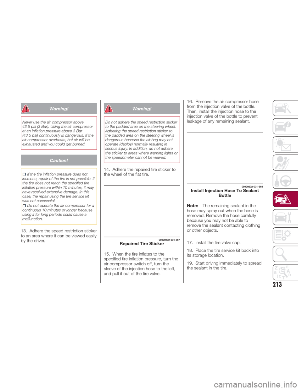
14. Adhere the repaired tire sticker to
the wheel of the flat tire.
15. When the tire inflates to the
specified tire inflation pressure, turn the
air compressor switch off, turn the
sleeve of the injection hose to the left,
and pull it out of the tire valve. 16. Remove the air compressor hose
from the injection valve of the bottle.
Then, install the injection hose to the
injection valve of the bottle to prevent
leakage of any remaining sealant.
Note:
The remaining sealant in the
hose may spray out when the hose is
removed. Remove the hose carefully
because you may not be able to
remove the sealant contacting clothing
or other objects.
17. Install the tire valve cap.
18. Place the tire service kit back into
its storage location.
19. Start driving immediately to spread
the sealant in the tire.
08020202-031-667Repaired Tire Sticker
08020202-031-668Install Injection Hose To Sealant Bottle
213
Page 219 of 300
13. Reinsert the valve core into the
valve and turn it clockwise to install.
Note:
The tire sealant cannot be reused.
If the tire sealant kit has been used, or
is expired, purchase new one at an
Authorized Dealer.
Do not throw away the empty tire
sealant bottle after use. Return the
empty tire sealant bottle to an
Authorized Dealer when replacing the
tire. The empty tire sealant bottle will
need to be used to extract and dispose
of the used sealant from the tire.
14. Install the injection hose to the tab
of the bottle to prevent leakage of any
remaining sealant.
15. Adhere the speed restriction sticker
to an area where it can be viewed easily
by the driver.
Warning!
Do not adhere the speed restriction sticker
to the padded area on the steering wheel.
Adhering the speed restriction sticker to
the padded area on the steering wheel is
dangerous because the air bag may not
operate (deploy) normally resulting in
serious injury. In addition, do not adhere
the sticker to areas where warning lights or
the speedometer cannot be viewed.
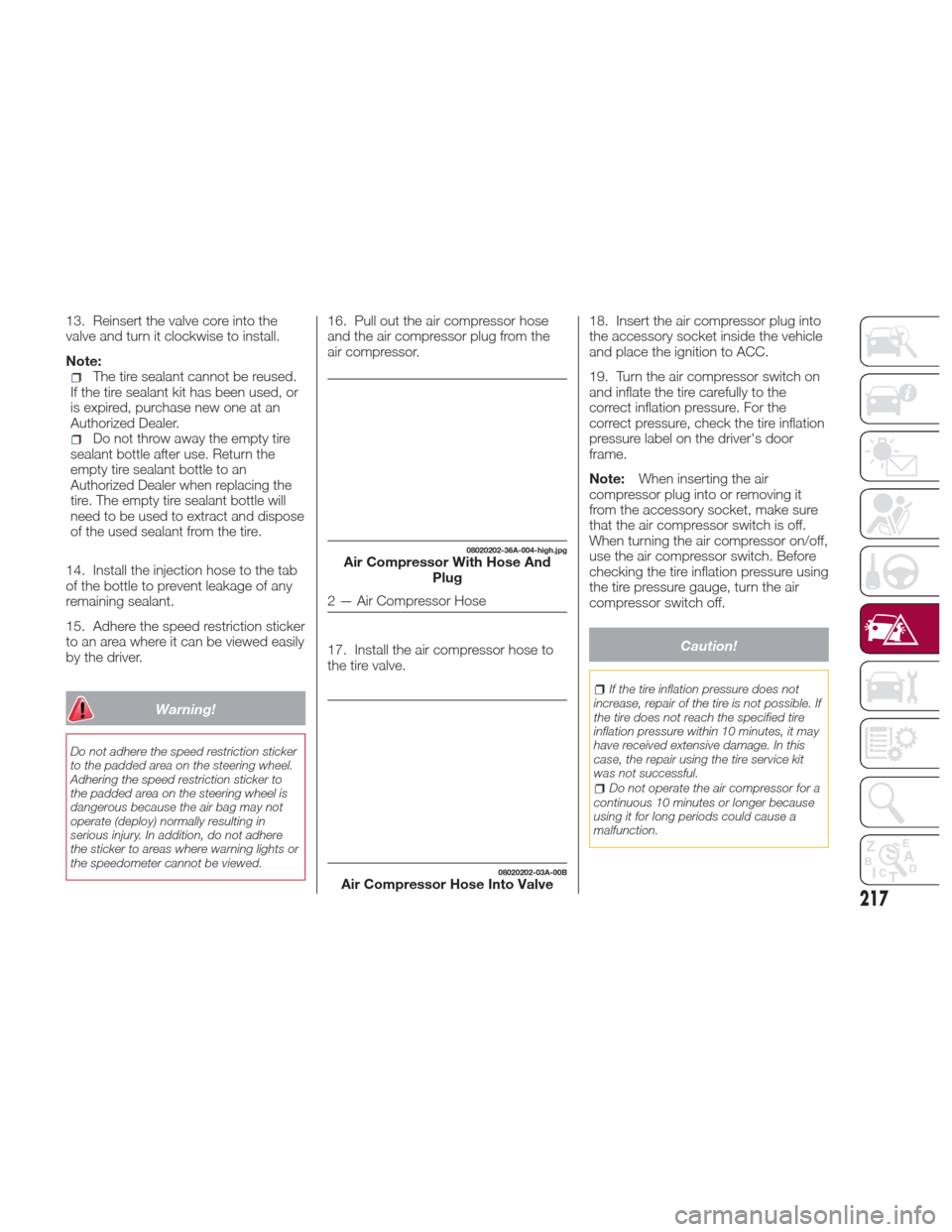
16. Pull out the air compressor hose
and the air compressor plug from the
air compressor.
17. Install the air compressor hose to
the tire valve. 18. Insert the air compressor plug into
the accessory socket inside the vehicle
and place the ignition to ACC.
19. Turn the air compressor switch on
and inflate the tire carefully to the
correct inflation pressure. For the
correct pressure, check the tire inflation
pressure label on the driver's door
frame.
Note:
When inserting the air
compressor plug into or removing it
from the accessory socket, make sure
that the air compressor switch is off.
When turning the air compressor on/off,
use the air compressor switch. Before
checking the tire inflation pressure using
the tire pressure gauge, turn the air
compressor switch off.
Caution!
If the tire inflation pressure does not
increase, repair of the tire is not possible. If
the tire does not reach the specified tire
inflation pressure within 10 minutes, it may
have received extensive damage. In this
case, the repair using the tire service kit
was not successful.
Do not operate the air compressor for a
continuous 10 minutes or longer because
using it for long periods could cause a
malfunction.
08020202-36A-004-high.jpgAir Compressor With Hose And Plug
2 — Air Compressor Hose
08020202-03A-00BAir Compressor Hose Into Valve
217
Page 225 of 300
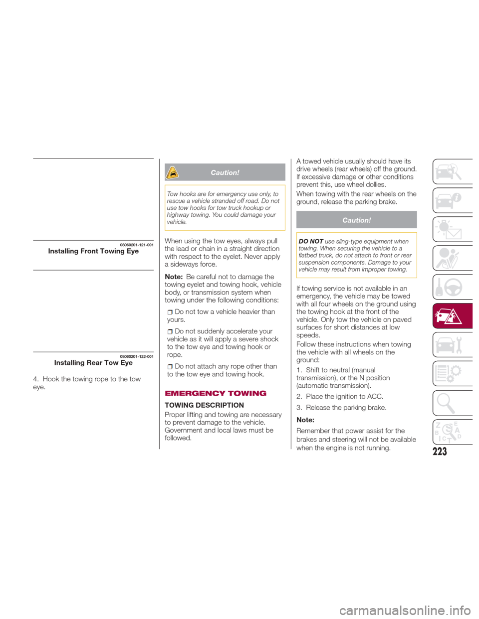
4. Hook the towing rope to the tow
eye.
Caution!
Tow hooks are for emergency use only, to
rescue a vehicle stranded off road. Do not
use tow hooks for tow truck hookup or
highway towing. You could damage your
vehicle.
When using the tow eyes, always pull
the lead or chain in a straight direction
with respect to the eyelet. Never apply
a sideways force.
Note:Be careful not to damage the
towing eyelet and towing hook, vehicle
body, or transmission system when
towing under the following conditions:
Do not tow a vehicle heavier than
yours.
Do not suddenly accelerate your
vehicle as it will apply a severe shock
to the tow eye and towing hook or
rope.
Do not attach any rope other than
to the tow eye and towing hook.
EMERGENCY TOWING
TOWING DESCRIPTION
Proper lifting and towing are necessary
to prevent damage to the vehicle.
Government and local laws must be
followed.
A towed vehicle usually should have its
drive wheels (rear wheels) off the ground.
If excessive damage or other conditions
prevent this, use wheel dollies.
When towing with the rear wheels on the
ground, release the parking brake.
Caution!
DO NOT use sling-type equipment when
towing. When securing the vehicle to a
flatbed truck, do not attach to front or rear
suspension components. Damage to your
vehicle may result from improper towing.
If towing service is not available in an
emergency, the vehicle may be towed
with all four wheels on the ground using
the towing hook at the front of the
vehicle. Only tow the vehicle on paved
surfaces for short distances at low
speeds.
Follow these instructions when towing
the vehicle with all wheels on the
ground:
1. Shift to neutral (manual
transmission), or the N position
(automatic transmission).
2. Place the ignition to ACC.
3. Release the parking brake.
Note:
Remember that power assist for the
brakes and steering will not be available
when the engine is not running.
08060201-121-001Installing Front Towing Eye
08060201-122-001Installing Rear Tow Eye
223
Page 230 of 300

Mileage or time passed(whichever comes first)
10,000
20,000
30,000
40,000
50,000
60,000
70,000
80,000
90,000
100,000
110,000
120,000
130,000
140,000
150,000
Years123 456789101112131415
Or Kilometers16,000
32,000
48,000
64,000
80,000
96,000
112,000
128,000
144,000
160,000
176,000
192,000
208,000
224,000
240,000
Check engine control
system operation (via
diagnostic tool). •••••••••••••••
Visually inspect condition
of: exterior bodywork,
underbody protection,
pipes and hoses (exhaust -
fuel system - brakes),
rubber elements (boots,
sleeves, bushings, etc.). •••• • • •
Visually inspect conditions
of steering elements and
check their operation. •••• • • •
Check the front and rear
suspension, tie rods, CV
Joints, and replace if
necessary. •••• • • •
Check endfloat of wheel
bearings. •••• • • •
228
SERVICING AND MAINTENANCE