2017 DODGE GRAND CARAVAN engine
[x] Cancel search: enginePage 249 of 530

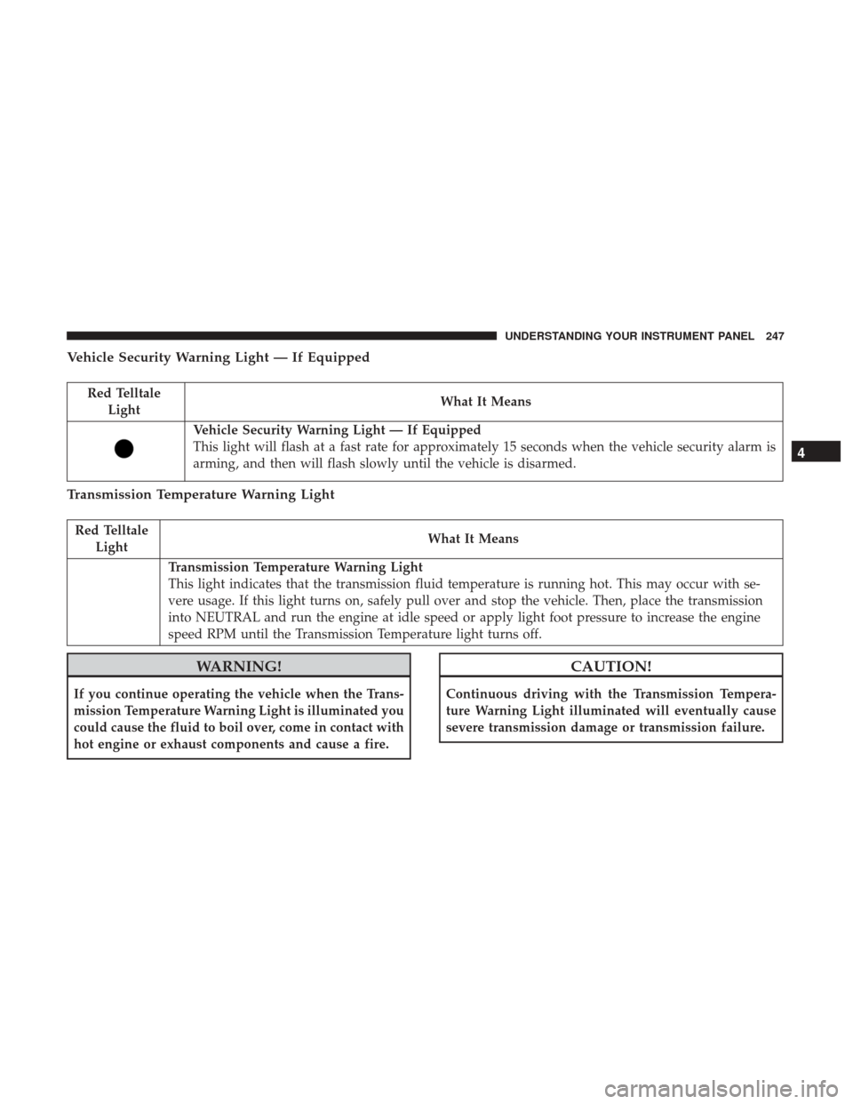
Vehicle Security Warning Light — If Equipped
Red TelltaleLight What It Means
Vehicle Security Warning Light — If Equipped
This light will flash at a fast rate for approximately 15 seconds when the vehicle security alarm is
arming, and then will flash slowly until the vehicle is disarmed.
Transmission Temperature Warning Light
Red Telltale
Light What It Means
Transmission Temperature Warning Light
This light indicates that the transmission fluid temperature is running hot. This may occur with se-
vere usage. If this light turns on, safely pull over and stop the vehicle. Then, place the transmission
into NEUTRAL and run the engine at idle speed or apply light foot pressure to increase the engine
speed RPM until the Transmission Temperature light turns off.
WARNING!
If you continue operating the vehicle when the Trans-
mission Temperature Warning Light is illuminated you
could cause the fluid to boil over, come in contact with
hot engine or exhaust components and cause a fire.
CAUTION!
Continuous driving with the Transmission Tempera-
ture Warning Light illuminated will eventually cause
severe transmission damage or transmission failure.
4
UNDERSTANDING YOUR INSTRUMENT PANEL 247
Page 252 of 530

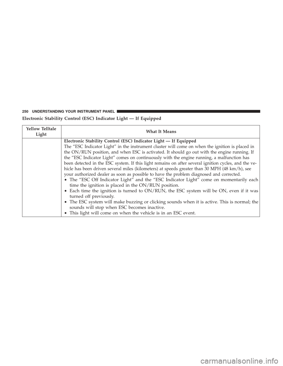
Electronic Stability Control (ESC) Indicator Light — If Equipped
Yellow TelltaleLight What It Means
Electronic Stability Control (ESC) Indicator Light — If Equipped
The “ESC Indicator Light” in the instrument cluster will come on when the ignition is placed in
the ON/RUN position, and when ESC is activated. It should go out with the engine running. If
the “ESC Indicator Light” comes on continuously with the engine running, a malfunction has
been detected in the ESC system. If this light remains on after several ignition cycles, and the ve-
hicle has been driven several miles (kilometers) at speeds greater than 30 MPH (48 km/h), see
your authorized dealer as soon as possible to have the problem diagnosed and corrected.
•
The “ESC Off Indicator Light” and the “ESC Indicator Light” come on momentarily each
time the ignition is placed in the ON/RUN position.
• Each time the ignition is turned to ON/RUN, the ESC system will be ON, even if it was
turned off previously.
• The ESC system will make buzzing or clicking sounds when it is active. This is normal; the
sounds will stop when ESC becomes inactive.
• This light will come on when the vehicle is in an ESC event.
250 UNDERSTANDING YOUR INSTRUMENT PANEL
Page 254 of 530

Low Washer Fluid Indicator Light — If Equipped
Yellow TelltaleLight What It Means
Low Washer Fluid Indicator Light — If Equipped
This indicator will illuminate when the windshield washer fluid is low.
Engine Check/Malfunction Indicator Light (MIL)
Yellow Telltale
Light What It Means
Engine Check/Malfunction Indicator Light (MIL)
The Engine Check/Malfunction Indicator Light (MIL) is a part of an Onboard Diagnostic System
called OBD II that monitors engine and automatic transmission control systems. The light will
illuminate when the ignition is in the ON/RUN position before engine start. If the bulb does not
come on when turning the key from OFF to ON/RUN, have the condition checked promptly.
Certain conditions, such as a loose or missing gas cap, poor quality fuel, etc., may illuminate the
light after engine start. The vehicle should be serviced if the light stays on through several typical
driving styles. In most situations, the vehicle will drive normally and will not require towing.
When the engine is running, the MIL may flash to alert serious conditions that could lead to im-
mediate loss of power or severe catalytic converter damage. The vehicle should be serviced as
soon as possible if this occurs.
252 UNDERSTANDING YOUR INSTRUMENT PANEL
Page 255 of 530

WARNING!
A malfunctioning catalytic converter, as referenced
above, can reach higher temperatures than in normal
operating conditions. This can cause a fire if you drive
slowly or park over flammable substances such as dry
plants, wood, cardboard, etc. This could result in death
or serious injury to the driver, occupants or others.
CAUTION!
Prolonged driving with the Malfunction Indicator
Light (MIL) on could cause damage to the engine
control system. It also could affect fuel economy and
driveability. If the MIL is flashing, severe catalytic
converter damage and power loss will soon occur.
Immediate service is required.
4
UNDERSTANDING YOUR INSTRUMENT PANEL 253
Page 265 of 530

permanently unavailable. The driver will receive an
Instrument Cluster Display message and the BSM dis-
play warning in both mirrors will be permanently
illuminated. If this message is present, see an authorized
dealer.
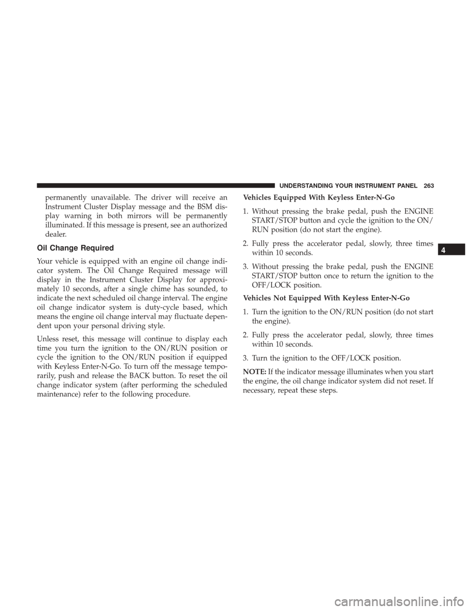
Oil Change Required
Your vehicle is equipped with an engine oil change indi-
cator system. The Oil Change Required message will
display in the Instrument Cluster Display for approxi-
mately 10 seconds, after a single chime has sounded, to
indicate the next scheduled oil change interval. The engine
oil change indicator system is duty-cycle based, which
means the engine oil change interval may fluctuate depen-
dent upon your personal driving style.
Unless reset, this message will continue to display each
time you turn the ignition to the ON/RUN position or
cycle the ignition to the ON/RUN position if equipped
with Keyless Enter-N-Go. To turn off the message tempo-
rarily, push and release the BACK button. To reset the oil
change indicator system (after performing the scheduled
maintenance) refer to the following procedure.Vehicles Equipped With Keyless Enter-N-Go
1. Without pressing the brake pedal, push the ENGINE
START/STOP button and cycle the ignition to the ON/
RUN position (do not start the engine).
2. Fully press the accelerator pedal, slowly, three times within 10 seconds.
3. Without pressing the brake pedal, push the ENGINE START/STOP button once to return the ignition to the
OFF/LOCK position.
Vehicles Not Equipped With Keyless Enter-N-Go
1. Turn the ignition to the ON/RUN position (do not start the engine).
2. Fully press the accelerator pedal, slowly, three times within 10 seconds.
3. Turn the ignition to the OFF/LOCK position.
NOTE: If the indicator message illuminates when you start
the engine, the oil change indicator system did not reset. If
necessary, repeat these steps.
4
UNDERSTANDING YOUR INSTRUMENT PANEL 263
Page 268 of 530

To Reset A Trip Function
Reset will only occur while a resettable function is selected
(highlighted). Push and hold the RIGHT button to clear the
resettable function being displayed.
Tire Pressure
Push and release theUPorDOWNarrow button
until “Tire PSI:” displays highlighted in the Instrument
Cluster Display. Push and release the RIGHT
arrow
button to view a graphic of the vehicle with a tire
pressure value at each corner of the graphic.
Units
Push and release the UPorDOWNarrow button
until “Units” displays highlighted in the Instrument
Cluster Display and push the RIGHT
arrow button.
The Instrument Cluster Display, odometer, and naviga-
tion system (if equipped) can be changed between
English and Metric units of measure. To make your
selection, scroll up or down until the preferred setting is
highlighted, then push and release the RIGHT
arrow
button until a check-mark appears next to the setting,
showing that the setting has been selected. Vehicle Info (Customer Information Features)
Push and release the
UPorDOWNarrow button
until “Vehicle Info” displays in the Instrument Cluster
Display. Then, push and release the RIGHT
arrow
button. Push and release the UP
orDOWNarrow
button to scroll through the available information dis-
plays, then push and release RIGHT
arrow button to
display any one of the following choices.
• Coolant Temp
Displays the actual coolant temperature.
• Oil Temp
Displays the actual oil temperature.
• Oil Pressure
Displays the actual oil pressure.
• Engine Hours
Displays the number of hours of engine operation.
Messages #
Select from Main Menu using the UPorDOWN
arrow button. This feature shows the number of
stored warning messages (in the # place holder). Push-
ing the RIGHT
arrow button will allow you to see
266 UNDERSTANDING YOUR INSTRUMENT PANEL
Page 269 of 530

what the stored messages are. Push and release theUP
orDOWNarrow button if there is more than one
message to step through the remaining stored messages.
Pushing the BACKbutton takes you back to the Main
Menu.
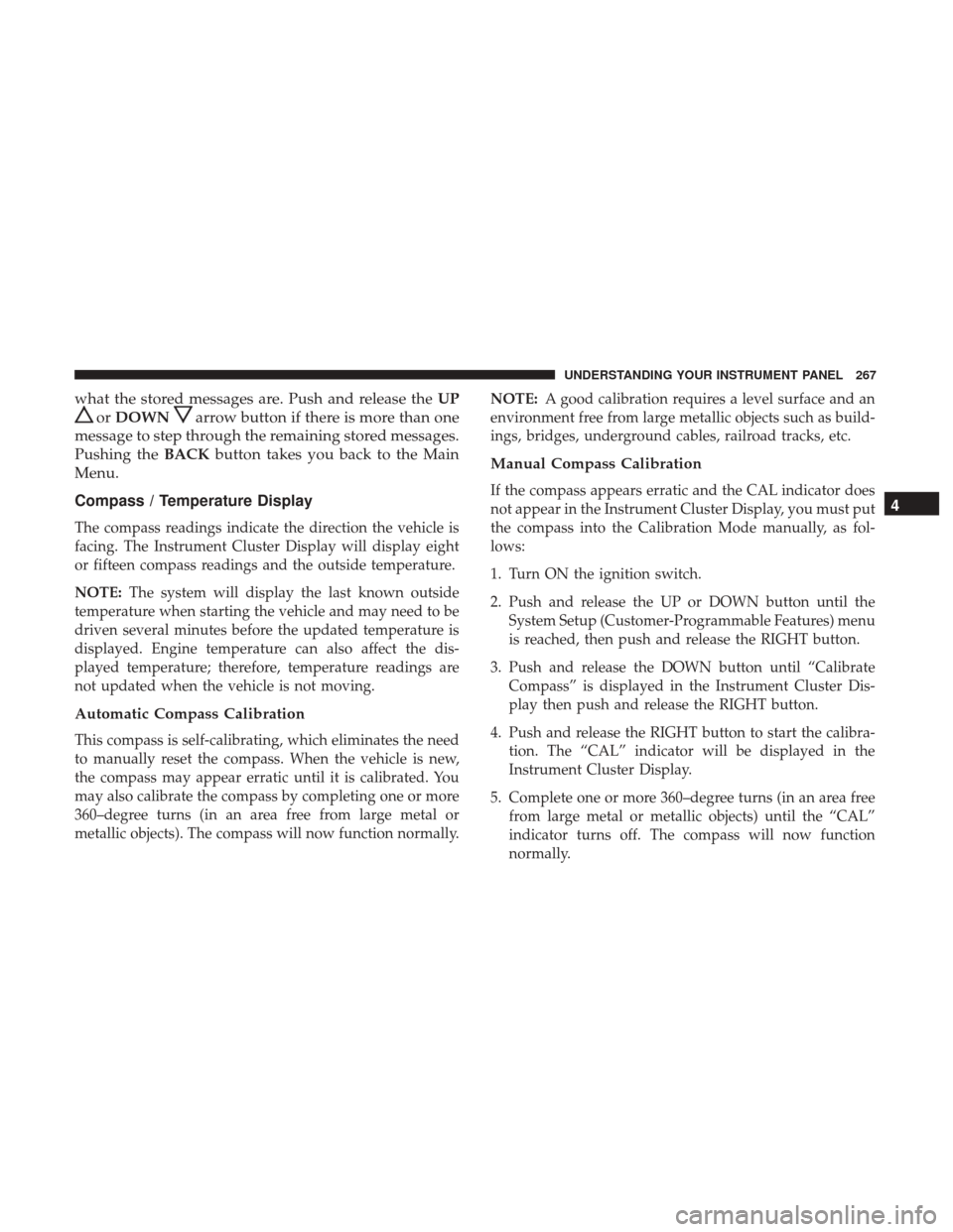
Compass / Temperature Display
The compass readings indicate the direction the vehicle is
facing. The Instrument Cluster Display will display eight
or fifteen compass readings and the outside temperature.
NOTE: The system will display the last known outside
temperature when starting the vehicle and may need to be
driven several minutes before the updated temperature is
displayed. Engine temperature can also affect the dis-
played temperature; therefore, temperature readings are
not updated when the vehicle is not moving.
Automatic Compass Calibration
This compass is self-calibrating, which eliminates the need
to manually reset the compass. When the vehicle is new,
the compass may appear erratic until it is calibrated. You
may also calibrate the compass by completing one or more
360–degree turns (in an area free from large metal or
metallic objects). The compass will now function normally. NOTE:
A good calibration requires a level surface and an
environment free from large metallic objects such as build-
ings, bridges, underground cables, railroad tracks, etc.
Manual Compass Calibration
If the compass appears erratic and the CAL indicator does
not appear in the Instrument Cluster Display, you must put
the compass into the Calibration Mode manually, as fol-
lows:
1. Turn ON the ignition switch.
2. Push and release the UP or DOWN button until the System Setup (Customer-Programmable Features) menu
is reached, then push and release the RIGHT button.
3. Push and release the DOWN button until “Calibrate Compass” is displayed in the Instrument Cluster Dis-
play then push and release the RIGHT button.
4. Push and release the RIGHT button to start the calibra- tion. The “CAL” indicator will be displayed in the
Instrument Cluster Display.
5. Complete one or more 360–degree turns (in an area free from large metal or metallic objects) until the “CAL”
indicator turns off. The compass will now function
normally.4
UNDERSTANDING YOUR INSTRUMENT PANEL 267
Page 322 of 530

This product incorporates proprietary technology under
license from Verance Corporation and is protected by U.S.
Patent 7,369,677 and other U.S. and worldwide patents
issued and pending as well as copyright and trade secret
protection for certain aspects of such technology. Cinavia is
a trademark of Verance Corporation. Copyright 2004-2010
Verance Corporation. All rights reserved by Verance. Re-
verse engineering or disassembly is prohibited.
•This product incorporates copyright protection technol-
ogy that is protected by U.S. patents and other intellec-
tual property rights. Use of this copyright protection
technology must be authorized by Macrovision, and is
intended for home and other limited viewing uses only
unless otherwise authorized by Macrovision. Reverse
engineering or disassembly is prohibited.
• Manufactured under license under U.S. Patent #’s:
5,451,942; 5,956,674; 5,974,380; 5,978,762; 6,487,535 &
other U.S. and worldwide patents issued & pending.
DTS is a registered trademark and the DTS logos,
Symbol and DTS 2.0 Channel are trademarks of DTS,
Inc. © 1996-2007 DTS, Inc. All Rights Reserved.
• Manufactured under license from Dolby Laboratories.
Dolby and the double-D symbol are trademarks of
Dolby Laboratories. ABOUT DIVX VIDEO: DivX is a digital video format
created by DivX, LLC, a subsidiary of Rovi Corporation.
This is an official DivX Certified device that plays DivX
video. Visit divx.com for more information and software
tools to convert your files into DivX videos.
ABOUT DIVX VIDEO-ON-DEMAND: This DivX Certified
device must be registered in order to play purchased DivX
Video-on-Demand (VOD) movies. To obtain your registra-
tion code, locate the DivX VOD section in your device
setup menu. Go to vod.divx.com for more information on
how to complete your registration.
DivX, DivX Certified and associated logos are trademarks
of Rovi Corporation or its subsidiaries and are used under
license.
Trademark
•
Java is a registered trademark of Oracle and/or its
affiliates.
CAUTION!
Use of controls or adjustments or performance of
procedures other than those specified herein may re-
sult in hazardous radiation exposure.
320 UNDERSTANDING YOUR INSTRUMENT PANEL