Page 342 of 530
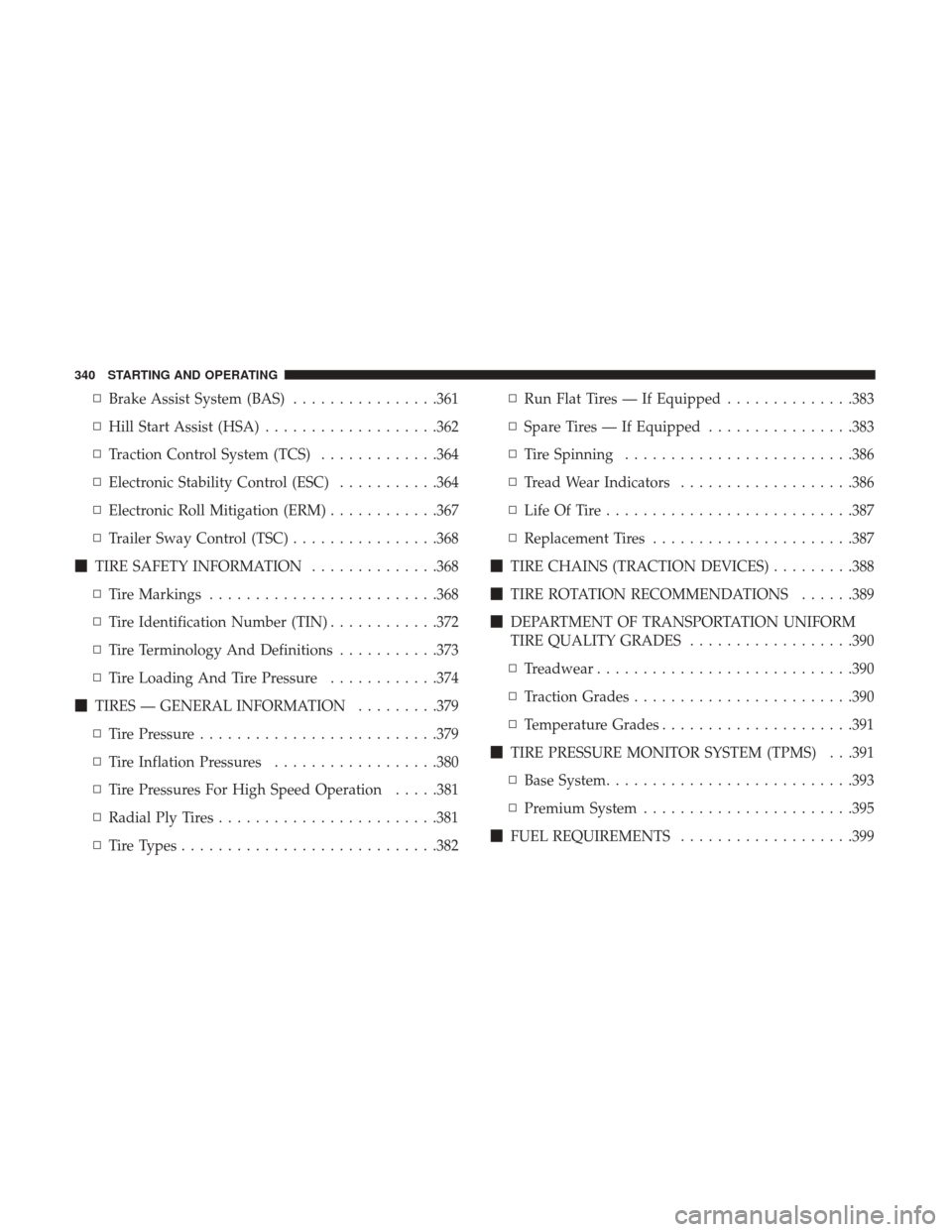
▫Brake Assist System (BAS) ................361
▫ Hill Start Assist (HSA) ...................362
▫ Traction Control System (TCS) .............364
▫ Electronic Stability Control (ESC) ...........364
▫ Electronic Roll Mitigation (ERM) ............367
▫ Trailer Sway Control (TSC) ................368
� TIRE SAFETY INFORMATION ..............368
▫ Tire Markings ........................ .368
▫ Tire Identification Number (TIN) ............372
▫ Tire Terminology And Definitions ...........373
▫ Tire Loading And Tire Pressure ............374
� TIRES — GENERAL INFORMATION .........379
▫ Tire Pressure ..........................379
▫ Tire Inflation Pressures ..................380
▫ Tire Pressures For High Speed Operation .....381
▫ Radial Ply Tires ........................381
▫ Tire Types ............................382 ▫
Run Flat Tires — If Equipped ..............383
▫ Spare Tires — If Equipped ................383
▫ Tire Spinning ........................ .386
▫ Tread Wear Indicators ...................386
▫ Life Of Tire .......................... .387
▫ Replacement Tires ..................... .387
� TIRE CHAINS (TRACTION DEVICES) .........388
� TIRE ROTATION RECOMMENDATIONS ......389
� DEPARTMENT OF TRANSPORTATION UNIFORM
TIRE QUALITY
GRADES..................390
▫ Treadwear ............................390
▫ Traction Grades ........................390
▫ Temperature Grades .....................391
� TIRE PRESSURE MONITOR SYSTEM (TPMS) . . .391
▫ Base System .......................... .393
▫ Premium System .......................395
� FUEL REQUIREMENTS ...................399
340 STARTING AND OPERATING
Page 363 of 530
WARNING!(Continued)
that could jeopardize the user ’s safety or the safety of
others.
ABS is designed to function with the OEM tires. Modifica-
tion may result in degraded ABS performance.
Anti-Lock Brake Warning Light
The yellow “Anti-Lock Brake Warning Light” will turn on
when the ignition switch is turned to the ON position and
may stay on for as long as four seconds.
If the “Anti-Lock Brake Warning Light” remains on or
comes on while driving, it indicates that the anti-lock
portion of the brake system is not functioning and that
service is required. However, the conventional brake sys-
tem will continue to operate normally if the “Brake System
Warning Light” is not on.
If the “Anti-Lock Brake Warning Light” is on, the brake
system should be serviced as soon as possible to restore the
benefits of anti-lock brakes. If the “Anti-Lock Brake Warn-
ing Light” does not come on when the ignition switch is
turned to the ON position, have the light repaired as soon
as possible.
Brake Assist System (BAS)
The BAS is designed to optimize the vehicle’s braking
capability during emergency braking maneuvers. The sys-
tem detects an emergency braking situation by sensing the
rate and amount of brake application and then applies
optimum pressure to the brakes. This can help reduce
braking distances. The BAS complements the anti-lock
brake system (ABS). Applying the brakes very quickly
results in the best BAS assistance. To receive the benefit of
the system, you must apply continuous braking pressure
during the stopping sequence, (do not “pump” the brakes).
Do not reduce brake pedal pressure unless braking is no
longer desired. Once the brake pedal is released, the BAS is
deactivated.
WARNING!
The Brake Assist System (BAS) cannot prevent the
natural laws of physics from acting on the vehicle, nor
can it increase the traction afforded by prevailing road
conditions. BAS cannot prevent collisions, including
those resulting from excessive speed in turns, driving
on very slippery surfaces, or hydroplaning. The capa-
bilities of a BAS-equipped vehicle must never be
(Continued)
5
STARTING AND OPERATING 361
Page 370 of 530

Trailer Sway Control (TSC)
TSC uses sensors in the vehicle to recognize an excessively
swaying trailer and will take the appropriate actions to
attempt to stop the sway. TSC will become active automati-
cally once an excessively swaying trailer is recognized.
Note that TSC cannot stop all trailers from swaying.
Always use caution when towing a trailer and follow the
trailer tongue weight recommendations. Refer to “Trailer
Towing” in this section for further information. When TSC
is functioning, the “ESC Activation/Malfunction Indicator
Light” will flash, the engine power may be reduced and
you may feel the brakes being applied to individual wheels
to attempt to stop the trailer from swaying. TSC is disabled
when the ESC system is in the “Partial Off” modes.
WARNING!
If TSC activates while driving, slow the vehicle down,
stop at the nearest safe location, and adjust the trailer
load to eliminate trailer sway.
TIRE SAFETY INFORMATION
Tire Markings
1 — U.S. DOT Safety Standards
Code (TIN)4 — Maximum Load
2 — Size Designation 5 — Maximum Pressure
3 — Service Description 6 — Treadwear, Traction and Temperature Grades
368 STARTING AND OPERATING
Page 371 of 530
NOTE:
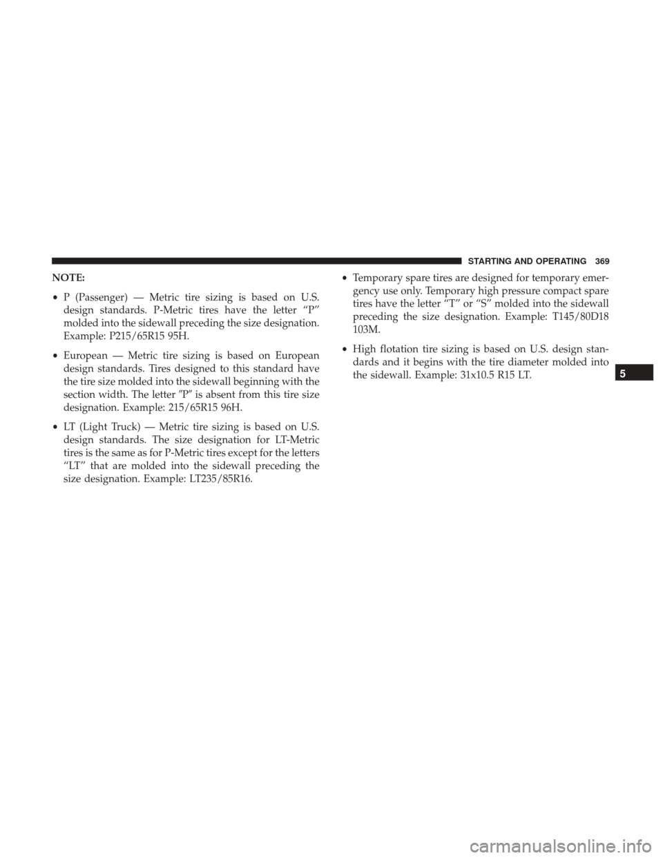
•P (Passenger) — Metric tire sizing is based on U.S.
design standards. P-Metric tires have the letter “P”
molded into the sidewall preceding the size designation.
Example: P215/65R15 95H.
• European — Metric tire sizing is based on European
design standards. Tires designed to this standard have
the tire size molded into the sidewall beginning with the
section width. The letter �P�is absent from this tire size
designation. Example: 215/65R15 96H.
• LT (Light Truck) — Metric tire sizing is based on U.S.
design standards. The size designation for LT-Metric
tires is the same as for P-Metric tires except for the letters
“LT” that are molded into the sidewall preceding the
size designation. Example: LT235/85R16. •
Temporary spare tires are designed for temporary emer-
gency use only. Temporary high pressure compact spare
tires have the letter “T” or “S” molded into the sidewall
preceding the size designation. Example: T145/80D18
103M.
• High flotation tire sizing is based on U.S. design stan-
dards and it begins with the tire diameter molded into
the sidewall. Example: 31x10.5 R15 LT.
5
STARTING AND OPERATING 369
Page 373 of 530
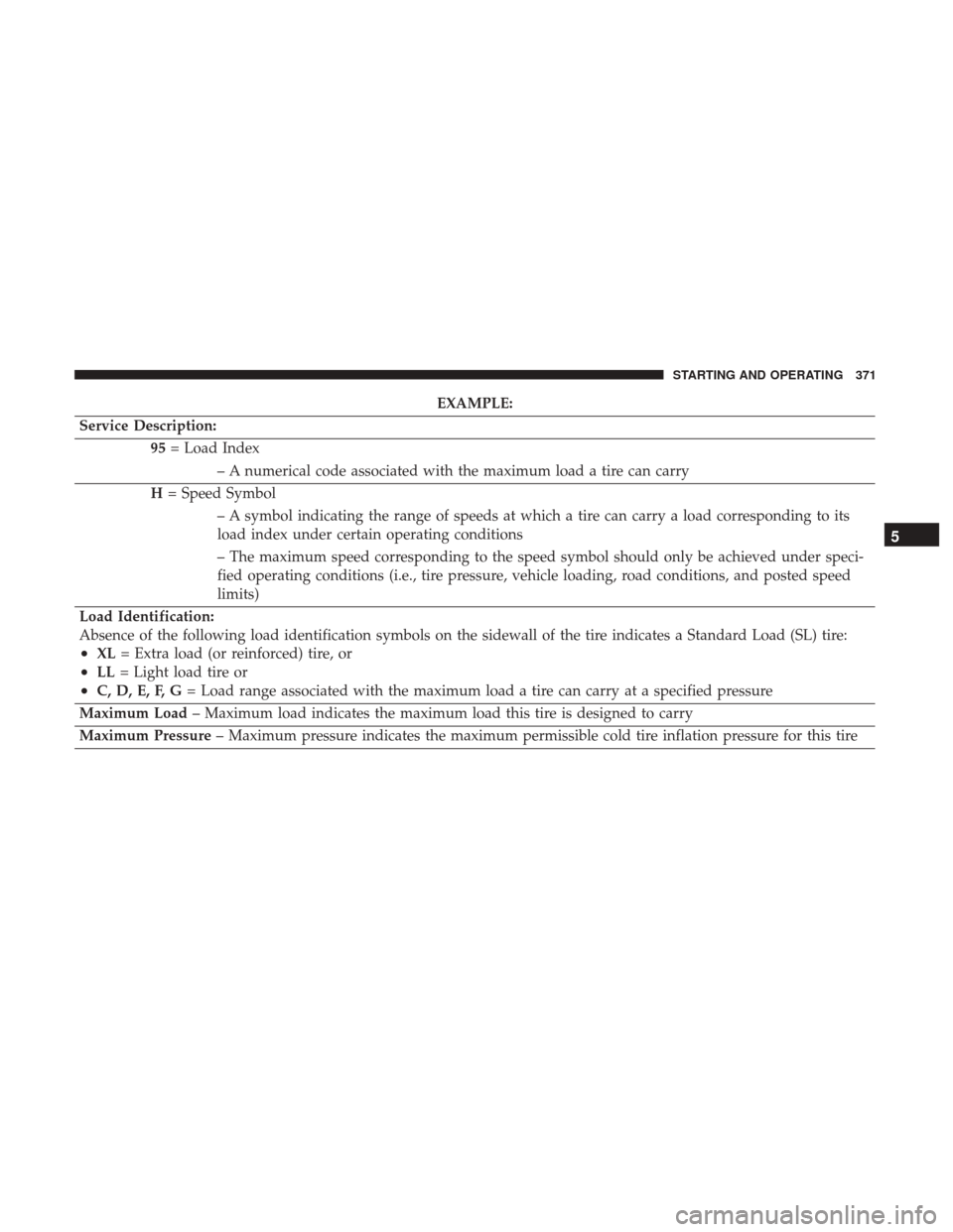
EXAMPLE:
Service Description: 95= Load Index
– A numerical code associated with the maximum load a tire can carry
H = Speed Symbol
– A symbol indicating the range of speeds at which a tire can carry a load corresponding to its
load index under certain operating conditions
– The maximum speed corresponding to the speed symbol should only be achieved under speci-
fied operating conditions (i.e., tire pressure, vehicle loading, road conditions, and posted speed
limits)
Load Identification:
Absence of the following load identification symbols on the sidewall of the tire indicates a Standard Load (SL) tire:
•XL = Extra load (or reinforced) tire, or
•LL= Light load tire or
•C, D, E, F, G = Load range associated with the maximum load a tire can carry at a specified pressure
Maximum Load – Maximum load indicates the maximum load this tire is designed to carry
Maximum Pressure – Maximum pressure indicates the maximum permissible cold tire inflation pressure for this tire
5
STARTING AND OPERATING 371
Page 375 of 530
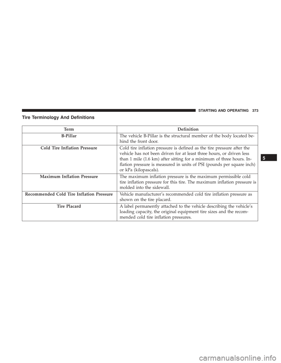
Tire Terminology And Definitions
TermDefinition
B-Pillar The vehicle B-Pillar is the structural member of the body located be-
hind the front door.
Cold Tire Inflation Pressure Cold tire inflation pressure is defined as the tire pressure after the
vehicle has not been driven for at least three hours, or driven less
than 1 mile (1.6 km) after sitting for a minimum of three hours. In-
flation pressure is measured in units of PSI (pounds per square inch)
or kPa (kilopascals).
Maximum Inflation Pressure The maximum inflation pressure is the maximum permissible cold
tire inflation pressure for this tire. The maximum inflation pressure is
molded into the sidewall.
Recommended Cold Tire Inflation Pressure Vehicle manufacturer’s recommended cold tire inflation pressure as
shown on the tire placard.
Tire Placard A label permanently attached to the vehicle describing the vehicle’s
loading capacity, the original equipment tire sizes and the recom-
mended cold tire inflation pressures.
5
STARTING AND OPERATING 373
Page 376 of 530
Tire Loading And Tire Pressure
Tire And Loading Information Placard Location
NOTE:The proper cold tire inflation pressure is listed on
the driver ’s side B-Pillar or the rear edge of the driver’s
side door.
Check the inflation pressure of each tire, including the
spare tire (if equipped), at least monthly and inflate to the
recommended pressure for your vehicle.
Example Tire Placard Location (Door)
Example Tire Placard Location (B-Pillar)
374 STARTING AND OPERATING
Page 377 of 530
WARNING!
•Overloading of your tires is dangerous. Overloading
can cause tire failure, affect vehicle handling, and
increase your stopping distance. Use tires of the
recommended load capacity for your vehicle. Never
overload them.
• Improperly inflated tires are dangerous and can
cause collisions. Under-inflation increases tire flex-
ing and can result in over-heating and tire failure.
Over-inflation reduces a tire’s ability to cushion
shock. Objects on the road and chuck holes can cause
damage that results in tire failure. Unequal tire
pressures can cause steering problems. You could
lose control of your vehicle. Over-inflated or under-
inflated tires can affect vehicle handling and can fail
suddenly, resulting in loss of vehicle control. Always
drive with each tire inflated to the recommended
cold tire inflation pressure.
Tire And Loading Information Placard
This placard tells you important information about the:
1. Number of people that can be carried in the vehicle.
2. Total weight your vehicle can carry.
3. Tire size designed for your vehicle.
4. Cold tire inflation pressures for the front, rear, and spare
tires.
Tire And Loading Information Placard
5
STARTING AND OPERATING 375