Page 336 of 530
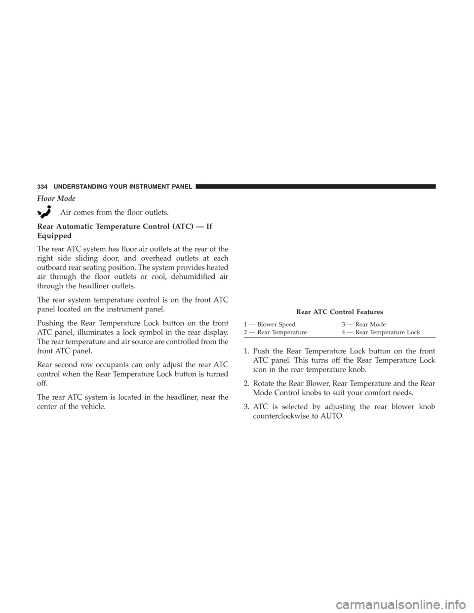
Floor ModeAir comes from the floor outlets.
Rear Automatic Temperature Control (ATC) — If
Equipped
The rear ATC system has floor air outlets at the rear of the
right side sliding door, and overhead outlets at each
outboard rear seating position. The system provides heated
air through the floor outlets or cool, dehumidified air
through the headliner outlets.
The rear system temperature control is on the front ATC
panel located on the instrument panel.
Pushing the Rear Temperature Lock button on the front
ATC panel, illuminates a lock symbol in the rear display.
The rear temperature and air source are controlled from the
front ATC panel.
Rear second row occupants can only adjust the rear ATC
control when the Rear Temperature Lock button is turned
off.
The rear ATC system is located in the headliner, near the
center of the vehicle. 1. Push the Rear Temperature Lock button on the front
ATC panel. This turns off the Rear Temperature Lock
icon in the rear temperature knob.
2. Rotate the Rear Blower, Rear Temperature and the Rear Mode Control knobs to suit your comfort needs.
3. ATC is selected by adjusting the rear blower knob counterclockwise to AUTO.
Rear ATC Control Features
1 — Blower Speed 3 — Rear Mode
2 — Rear Temperature 4 — Rear Temperature Lock
334 UNDERSTANDING YOUR INSTRUMENT PANEL
Page 337 of 530
Once the desired temperature is displayed, the ATC System
will automatically achieve and maintain that comfort level.
When the system is set up for your comfort level, it is not
necessary to change the settings. You will experience the
greatest efficiency by simply allowing the system to func-
tion automatically.
NOTE:
•It is not necessary to move the temperature settings. The
system automatically adjusts the temperature, mode and
fan speed to provide comfort as quickly as possible.
• The temperature can be displayed in English or Metric
units by selecting the “Display Units of Measure in”
customer-programmable feature. Refer to the “Instru-
ment Cluster Display” in this Section.
Rear Blower Control
The rear blower control knob can be manually set to off, or
any fixed blower speed, by rotating the knob from low to
high. This allows the rear seat occupants to control the
volume of air circulated in the rear of the vehicle.
CAUTION!
Interior air enters the Rear Automatic Temperature
Control System through an intake grille, located in the
right side trim panel behind the third row seats. The
heater outlets are located in the right side trim panel,
just behind the sliding door. Do not block or place
objects directly in front of the inlet grille or heater
outlets. The electrical system could overload causing
damage to the blower motor.
Rear Temperature Control
To change the temperature in the rear of the vehicle, rotate
the temperature knob counterclockwise to lower the tem-
perature, and clockwise to increase the temperature. The
rear temperature settings are displayed in the front ATC
panel.
When rear controls are locked by the front system, the Rear
Temperature Lock symbol on the temperature knob is
illuminated and any rear overhead adjustments are ig-
nored.
4
UNDERSTANDING YOUR INSTRUMENT PANEL 335
Page 338 of 530
Rear Mode Control
•Headliner Mode
Air comes from the outlets in the headliner. Each of
these outlets can be individually adjusted to direct
the flow of air. Moving the air vanes of the outlets to one
side will shut off the airflow.
• Bi-Level Mode
Air comes from both the headliner outlets and the
floor outlets.
NOTE: In many temperature positions, the Bi-Level mode
is designed to provide cooler air out of the headliner
outlets and warmer air from the floor outlets.
• Floor Mode
Air comes from the floor outlets.
Operating Tips
NOTE: Refer to the chart at the end of this section for
suggested control settings for various weather conditions.
Summer Operation
The engine cooling system must be protected with a
high-quality antifreeze coolant to provide proper corrosion
protection and to protect against engine overheating. OAT
coolant (conforming to MS.90032) is recommended. Refer
to “Maintenance Procedures” in “Maintaining Your Ve-
hicle” for proper coolant selection.
Winter Operation
To ensure the best possible heater and defroster perfor-
mance, make sure the engine cooling system is functioning
properly and the proper amount, type, and concentration
of coolant is used. Refer to “Maintenance Procedures” in
“Maintaining Your Vehicle” for proper coolant selection.
Use of the air Recirculation mode during Winter months is
not recommended, because it may cause window fogging.
336 UNDERSTANDING YOUR INSTRUMENT PANEL
Page 339 of 530
Vacation/Storage
Before you store your vehicle, or keep it out of service (i.e.,
vacation) for two weeks or more, run the air conditioning
system at idle for about five minutes, in fresh air with the
blower setting on high. This will ensure adequate system
lubrication to minimize the possibility of compressor dam-
age when the system is started again.
Window Fogging
Vehicle windows tend to fog on the inside in mild, rainy
and/or humid weather. To clear the windows, select De-
frost or Mix mode and increase the front blower speed. Do
not use the Recirculation mode without A/C for long
periods, as fogging may occur.
Outside Air Intake
Make sure the air intake, located directly in front of the
windshield, is free of obstructions such as leaves. Leaves
collected in the air intake may reduce airflow, and if they
enter the plenum, they could plug the water drains. In
winter months, make sure the air intake is clear of ice,
slush, and snow.
A/C Air Filter
The climate control system filters out dust and pollen from
the air. Refer to “Air Conditioning” in “Maintaining Your
Vehicle” for filter replacement instructions.
4
UNDERSTANDING YOUR INSTRUMENT PANEL 337
Page 340 of 530
Operating Tips Chart
338 UNDERSTANDING YOUR INSTRUMENT PANEL
Page 348 of 530
ignition when the ignition is in the LOCK/OFF position,
and the transmission is locked in PARK whenever the
ignition is in the LOCK/OFF position.
NOTE:If a malfunction occurs, the system will trap the key
fob in the ignition to warn you that this safety feature is
inoperable. The engine can be started and stopped but the
key fob cannot be removed until you obtain service.
Brake/Transmission Shift Interlock System
This vehicle is equipped with a Brake Transmission Shift
Interlock System (BTSI) that holds the transmission gear
selector in PARK unless the brakes are applied. To shift the
transmission out of PARK, the ignition must be turned to
the ON/RUN mode (engine running or not) and the brake
pedal must be pressed.
Fuel Economy (ECON) Mode
The Fuel Economy (ECON) mode can improve the vehi-
cle’s overall fuel economy during normal driving condi-
tions. Push the “econ” switch in the center stack of the
instrument panel and a green light will indicate the ECON
mode is engaged. When the Fuel Economy (ECON) Mode is engaged, the
vehicle control systems will change the following:
•
The transmission will upshift sooner and downshift
later.
• The transmission will skip select gears during shifts to
allow the engine to operate at lower speeds.
• The torque converter clutch may engage at lower engine
speeds and remain on longer.
• The engine idle speed will be lower.
Fuel Economy Mode Switch
346 STARTING AND OPERATING
Page 359 of 530

WARNING!
Fluid level should be checked on a level surface and
with the engine off to prevent injury from moving
parts and to ensure accurate fluid level reading. Do not
overfill. Use only manufacturer’s recommended power
steering fluid.
If necessary, add fluid to restore to the proper indicated
level. With a clean cloth, wipe any spilled fluid from all
surfaces.
PARKING BRAKE
Before leaving the vehicle, make sure that the parking
brake is fully applied and place the gear selector in the
PARK position.
The foot operated parking brake is positioned below the
lower left corner of the instrument panel. To apply the park
brake, firmly push the park brake pedal fully. To release the
parking brake, press the park brake pedal a second time
and let your foot up as you feel the brake disengage. When the parking brake is applied with the ignition switch
in the ON position, the “Brake Warning Light” in the
instrument cluster will illuminate.
NOTE:
•
When the parking brake is applied and the automatic
transmission is placed in gear, the “Brake Warning
Light” will flash. If vehicle speed is detected, a chime
will sound to alert the driver. Fully release the parking
brake before attempting to move the vehicle.
• This light only shows that the parking brake is applied.
It does not show the degree of brake application.Parking Brake
5
STARTING AND OPERATING 357
Page 365 of 530
Towing With HSA
HSA will also provide assistance to mitigate roll back while
towing a trailer.
WARNING!
•If you use a trailer brake controller with your trailer,
the trailer brakes may be activated and deactivated
with the brake switch. If so, there may not be enough
brake pressure to hold both the vehicle and the
trailer on a hill when the brake pedal is released. In
order to avoid rolling down an incline while resum-
ing acceleration, manually activate the trailer brake
or apply more vehicle brake pressure prior to releas-
ing the brake pedal.
• HSA is not a parking brake. Always apply the
parking brake fully when leaving your vehicle. Also,
be certain to leave the transmission in PARK.
• Failure to follow these warnings may cause the
vehicle to roll down the incline and could collide
with another vehicle, object or person, and cause
serious or fatal injury. Always remember to use the
parking brake while parking on a hill and that the
driver is responsible for braking the vehicle.
Disabling And Enabling HSA
This feature can be turned on or turned off. To change the
current setting, proceed as follows:
• For vehicles equipped with the instrument cluster dis-
play, refer to “Instrument Cluster Display” in “Under-
standing Your Instrument Panel” for further informa-
tion.
• If disabling HSA using Uconnect Settings, refer to
“Uconnect Settings” in “Understanding Your Instrument
Panel” for further information.
For vehicles not equipped with the instrument cluster
display, perform the following steps:
1. Center the steering wheel (front wheels pointing straight forward).
2. Shift the transmission into PARK.
3. Apply the parking brake.
4. Start the engine.
5. Rotate the steering wheel slightly more than one-half turn to the left.
5
STARTING AND OPERATING 363