Page 9 of 32

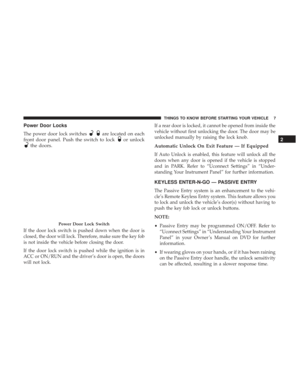
Power Door Locks
The power door lock switchesare located on each
front door panel. Push the switch to lock
or unlock
the doors.
If the door lock switch is pushed down when the door is
closed, the door will lock. Therefore, make sure the key fob
is not inside the vehicle before closing the door.
If the door lock switch is pushed while the ignition is in
ACC or ON/RUN and the driver’s door is open, the doors
will not lock. If a rear door is locked, it cannot be opened from inside the
vehicle without first unlocking the door. The door may be
unlocked manually by raising the lock knob.
Automatic Unlock On Exit Feature — If Equipped
If Auto Unlock is enabled, this feature will unlock all the
doors when any door is opened if the vehicle is stopped
and in PARK. Refer to “Uconnect Settings” in “Under-
standing Your Instrument Panel” for further information.
KEYLESS ENTER-N-GO — PASSIVE ENTRY
The Passive Entry system is an enhancement to the vehi-
cle’s Remote Keyless Entry system. This feature allows you
to lock and unlock the vehicle’s door(s) without having to
push the key fob lock or unlock buttons.
NOTE:
•
Passive Entry may be programmed ON/OFF. Refer to
“Uconnect Settings” in “Understanding Your Instrument
Panel” in your Owner ’s Manual on DVD for further
information.
• If wearing gloves on your hands, or if it has been raining
on the Passive Entry door handle, the unlock sensitivity
can be affected, resulting in a slower response time.
Power Door Lock Switch
2
THINGS TO KNOW BEFORE STARTING YOUR VEHICLE 7
Page 10 of 32
.
To Unlock From The Driver ’s Side:
With a")
•If the vehicle is unlocked by Passive Entry and no door
goes ajar within 60 seconds, the vehicle will re-lock and
will arm the theft alarm (if equipped).
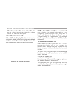
To Unlock From The Driver ’s Side:
With a valid Passive Entry key fob within 5 ft (1.5 m) of the
driver ’s door handle, grab the driver ’s front door handle to
unlock the driver ’s door automatically. The interior door
panel lock knob will raise when the door is unlocked. NOTE:
If “Unlock All Doors 1st Press” is programmed all
doors will unlock when you grab hold of the driver ’s front
door handle. To select between “Unlock Driver Door 1st
Press” and “Unlock All Doors 1st Press,” refer to
“Uconnect Settings” in “Understanding Your Instrument
Panel” in your Owner ’s Manual on DVD for further
information.
To Unlock From The Passenger Side:
With a valid Passive Entry key fob within 5 ft (1.5 m) of the
passenger door handle, grab the front passenger door
handle to unlock only the front doors automatically. The
interior door panel lock knob will raise when the door is
unlocked.
The vehicle doors can also be locked by using the key fob
lock button or the lock button located on the vehicle’s
interior door panel.
OCCUPANT RESTRAINTS
Driver/passenger air bags affect the way police equipment
can be safely mounted in police vehicles.
Any surface that could come into contact with an air bag,
once it has been deployed, must not damage the air bag or
alter its deployment path.
Grabbing The Driver ’s Door Handle
8 THINGS TO KNOW BEFORE STARTING YOUR VEHICLE
Page 11 of 32
, must be
installed such that it will not interfere or come in contact
with a deploying air bag. Air")
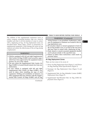
The addition of the supplemental equipment (such as
radios, weapons, mounting brackets, cage, etc.), must be
installed such that it will not interfere or come in contact
with a deploying air bag. Air bag deployment zones are
described below. Sharp edges, corners or protrusions on
supplemental equipment, could damage the nylon air bag
material and reduce the effectiveness of the air bag during
a deployment.
WARNING!
•Vehicles equipped with left and right Supplemental
Side Curtain Air Bags (SABIC) must use police cages,
which have been approved by the equipment manu-
facturer, for use in the vehicle.
• The area where the Supplemental Side Curtain Air
Bags (SABIC) is located should remain free from any
obstructions.
• If your vehicle is equipped with left and right
Supplemental Side Curtain Air Bags (SABIC), care
must be taken when installing any type of roof
equipment. Drilling and installation of fasteners or
other equipment that may interfere with the Supple-
mental Side Curtain Air Bags (SABIC) and air bag
(Continued)
WARNING! (Continued)
wiring harness is not permitted. Furthermore, make
sure no equipment or fasteners are located in the air
bag deployment zone.
• Do not place objects or mount equipment in front of
the air bag module cover, or in front of the seat areas
that may come in contact with a deploying air bag.
• Dash, tunnel or console mounted equipment should
not be placed outside of the specified zone.
• Failure to follow these instructions could result in
personal injury.
Air Bag Deployment Zones
There are four zones to be aware of:
1. Driver Air Bag Deployment Zone (Figure 1), and Driver Air Bag/Steering Wheel Specifications (Figure 2)
2. Passenger Air Bag Deployment Zone (Figure 3) and (Figure 4)
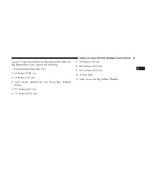
3. Supplemental Side Air Bag Inflatable Curtain (SABIC) Deployment Zone (Figure 5)
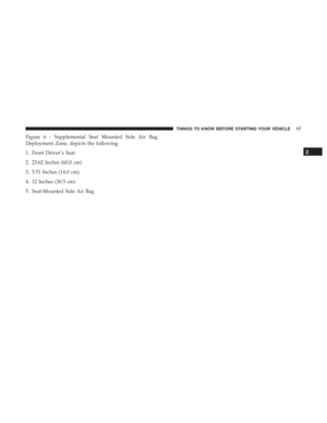
4. Supplemental Seat-Mounted Side Air Bag (SAB) De- ployment Zone (Figure 6)
2
THINGS TO KNOW BEFORE STARTING YOUR VEHICLE 9
Page 12 of 32
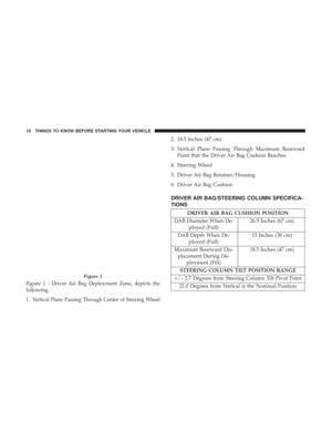
Figure 1 - Driver Air Bag Deployment Zone, depicts the
following.
1.
Vertical Plane Passing Through Center of Steering Wheel
2. 18.5 Inches (47 cm)
3. Vertical Plane Passing Through Maximum RearwardPoint that the Driver Air Bag Cushion Reaches
4. Steering Wheel
5. Driver Air Bag Retainer/Housing
6. Driver Air Bag Cushion
DRIVER AIR BAG/STEERING COLUMN SPECIFICA-
TIONS
DRIVER AIR BAG CUSHION POSITION
DAB Diameter When De- ployed (Full) 26.5 Inches (67 cm)
DAB Depth When De- ployed (Full) 15 Inches (38 cm)
Maximum Rearward Dis- placement During De- ployment (Fill) 18.5 Inches (47 cm)
STEERING COLUMN TILT POSITION RANGE
+/– 2.7 Degrees from Steering Column Tilt Pivot Point 21.0 Degrees from Vertical is the Nominal Position
Figure 1
10 THINGS TO KNOW BEFORE STARTING YOUR VEHICLE
Page 13 of 32
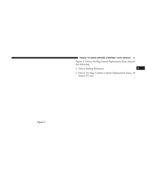
Figure 2 - Driver Air Bag Lateral Deployment Zone, depicts
the following.
1. Driver Seating Reference
2. Driver Air Bag Cushion Lateral Deployment Zone, 28Inches (71 cm)
Figure 2
2
THINGS TO KNOW BEFORE STARTING YOUR VEHICLE 11
Page 14 of 32
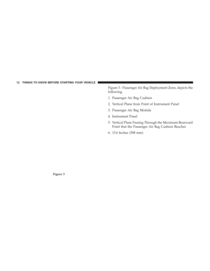
Figure 3 - Passenger Air Bag Deployment Zone, depicts the
following.
1. Passenger Air Bag Cushion
2. Vertical Plane from Point of Instrument Panel
3. Passenger Air Bag Module
4. Instrument Panel
5. Vertical Plane Passing Through the Maximum RearwardPoint that the Passenger Air Bag Cushion Reaches
6. 15.6 Inches (398 mm)
Figure 3
12 THINGS TO KNOW BEFORE STARTING YOUR VEHICLE
Page 15 of 32
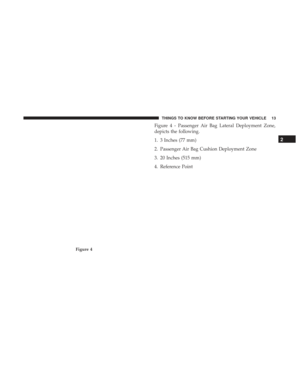
Figure 4 - Passenger Air Bag Lateral Deployment Zone,
depicts the following.
1. 3 Inches (77 mm)
2. Passenger Air Bag Cushion Deployment Zone
3. 20 Inches (515 mm)
4. Reference Point
Figure 4
2
THINGS TO KNOW BEFORE STARTING YOUR VEHICLE 13
Page 16 of 32
Figure 5
14 THINGS TO KNOW BEFORE STARTING YOUR VEHICLE


3. Vertical Plane Passing Through Maximum RearwardPo")

Figure 2
2
THINGS TO KNOW BEFO")


2. Passenger Air Bag Cushion Deployment Zone
3. 20 Inches (515 mm)
4. Reference Point
Figure 4
2
THINGS")
