2017 CHEVROLET MALIBU clock
[x] Cancel search: clockPage 206 of 419
Chevrolet Malibu Owner Manual (GMNA-Localizing-U.S./Canada/Mexico-10122664) - 2017 - crc - 5/23/16
Climate Controls 205
Climate Controls
Climate Control Systems
Climate Control Systems . . . . . 205Dual Automatic ClimateControl System . . . . . . . . . . . . . 208
Air Vents
Air Vents . . . . . . . . . . . . . . . . . . . . . . 211
Maintenance
Passenger Compartment AirFilter . . . . . . . . . . . . . . . . . . . . . . . . 212Service . . . . . . . . . . . . . . . . . . . . . . . 213
Climate Control Systems
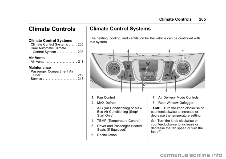
The heating, cooling, and ventilation for the vehicle can be controlled withthis system.
1. Fan Control
2. MAX Defrost
3. A/C (Air Conditioning) or Max/Eco Air Conditioning (Stop/Start Only)
4. TEMP (Temperature Control)
5. Driver and Passenger HeatedSeats (If Equipped)
6. Recirculation
7. Air Delivery Mode Controls
8. Rear Window Defogger
TEMP :Turn the knob clockwise orcounterclockwise to increase ordecrease the temperature setting.
^:Turn the knob clockwise orcounterclockwise to increase ordecrease the fan speed or turn thefan off.
Page 210 of 419
Chevrolet Malibu Owner Manual (GMNA-Localizing-U.S./Canada/Mexico-10122664) - 2017 - crc - 5/23/16
Climate Controls 209
Press@to manually select
recirculation and the indicator lightwill turn on. Press it again to selectoutside air and the indicator light willturn off.
Driver and PassengerTe m p e r a t u r e C o n t r o l s :Thetemperature can be adjustedseparately for the driver and thepassenger. Turn the knob clockwiseor counterclockwise to increase ordecrease the driver or passengertemperature setting.
SYNC :Press to link the passengertemperature settings to the driversetting. The SYNC indicator light willturn on. When the passengersettings are adjusted, the SYNCindicator light turns off.
Manual Operation
O:Press to turn the fan off or on.
^Qor^R:Press to increase ordecrease the fan speed. The fanspeed setting appears on the maindisplay. When the fan speed isdecreased completely, the fan turnsoff. Pressing either button cancels
automatic fan control and the fan iscontrolled manually. Press AUTO toreturn to automatic operation.
Air Delivery Mode Controls :
Press0,d,orcto change
the direction of the airflow. Anycombination of the three buttonscan be selected. The indicator lightin the button will turn on. Thecurrent mode appears in the displayscreen. Pressing any button cancelsautomatic air delivery control andthe direction of the airflow iscontrolled manually. Press AUTO toreturn to automatic operation.
To c h a n g e t h e c u r r e n t m o d e , s e l e c tone or more of the following modes:
0:Clears the windows of fog ormoisture. Air is directed to thewindshield.
d:Air is directed to the instrumentpanel outlets.
c:Air is directed to the flooroutlets.
0MAX :Air is directed to thewindshield, the fan runs at a higherspeed, and the temperature of theair is increased if not already at
maximum. This mode overrides theprevious mode selected and clearsfog or frost from the windshieldmore quickly. When the button ispressed again, the system returnsto the previous mode setting andfan speed.
For best results, clear all snow andice from the windshield beforedefrosting.
A/C :Press to turn the airconditioning system on or off. If thefan control is turned off or theoutside temperature falls belowfreezing, the air conditioner willnot run.
Pressing this button cancelsautomatic air conditioning and turnsoff the air conditioner. Press AUTOto return to automatic operation andthe air conditioner runsautomatically as needed. When theindicator light is on, the airconditioner runs automatically tocool the air inside the vehicle or todry the air needed to defog thewindshield faster.
Page 298 of 419
Chevrolet Malibu Owner Manual (GMNA-Localizing-U.S./Canada/Mexico-10122664) - 2017 - crc - 5/23/16
Vehicle Care 297
The coolant surge tank pressurecap can be removed when thecooling system, including the surgetank pressure cap and upperradiator hose, is no longer hot.
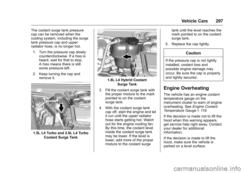
1. Turn the pressure cap slowlycounterclockwise. If a hiss isheard, wait for that to stop.Ahissmeansthereisstillsome pressure left.
2. Keep turning the cap andremove it.
1.5L L4 Turbo and 2.0L L4 Turbo
Coolant Surge Tank
1.8L L4 Hybrid Coolant
Surge Tank
3. Fill the coolant surge tank withthe proper mixture to the markpointed to on the coolantsurge tank.
4. With the coolant surge tankcap off, start the engine and letit run until the upper radiatorhose starts getting hot. Watchout for the engine cooling fan.By this time, the coolant levelinside the coolant surge tankmay be lower. If the level islower, add more of the propermixture to the coolant surge
tank until the level reaches themark pointed to on the coolantsurge tank.
5. Replace the cap tightly.
Caution
If the pressure cap is not tightly
installed, coolant loss and
possible engine damage may
occur. Be sure the cap is properly
and tightly secured.
Engine Overheating
The vehicle has an engine coolanttemperature gauge on theinstrument cluster to warn of engineoverheating. SeeEngine CoolantTe m p e r a t u r e G a u g e011 9.
If the decision is made not to lift thehood when this warning appears,get service help right away. Contactyour dealer for additionalinformation.
If the decision is made to lift thehood, make sure the vehicle isparked on a level surface.
Page 307 of 419
Chevrolet Malibu Owner Manual (GMNA-Localizing-U.S./Canada/Mexico-10122664) - 2017 - crc - 5/23/16
306 Vehicle Care
2. For the driver side bulb,remove the windshield washerbottle filler neck by firmlypulling it straight up and out ofthe bottle.
3. For hybrid vehicles, remove theengine air cleaner housing bygripping firmly and pullingstraight up.
4. Remove the cover from theback of the headlampassembly by turning itcounterclockwise.
5. Disconnect the electricalconnector.
6. Remove the bulb from the lampassembly by turningcounterclockwise.
7. Install a new bulb in the lampassembly.
8. Connect the electricalconnector.
9. Replace the cover from theback of the headlampassembly by turning itclockwise.
10. For the driver side, reinstall thewindshield washer bottle fillerneck by firmly pushing itstraight into the bottle. Makesure that the filler neck clipengages into the bracket onthe upper tie-bar.
11 . R e p l a c e t h e e n g i n e a i r c l e a n e rhousing by aligning the pegswith the grommets andpressing firmly down.
Front Turn Signal, Parking, and
Sidemarker Lamps
To r e p l a c e o n e o f t h e s e l a m p s :
1. For the driver side bulb,remove the windshield washerbottle filler neck by firmlypulling it straight up and out ofthe bottle.
2. For hybrid vehicles, remove theengine air cleaner housing bygripping firmly and pullingstraight up.
3. Remove the bulb socket fromthe headlamp assembly byturning it counterclockwise.
4. Remove the bulb from thesocket.
5. Replace the bulb in the bulbsocket.
6. Install the bulb socket in theheadlamp assembly by turningit clockwise.
7. For the driver side, reinstall thewindshield washer bottle fillerneck by firmly pushing itstraight into the bottle. Makesure that the filler neck clipengages into the bracket onthe upper tie-bar.
8. Replace the engine air cleanerhousing by aligning the pegswith the grommets andpressing firmly down.
Page 308 of 419
Chevrolet Malibu Owner Manual (GMNA-Localizing-U.S./Canada/Mexico-10122664) - 2017 - crc - 5/23/16
Vehicle Care 307
Taillamps, Turn Signal,
Stoplamps, and Back-Up
Lamps (LS and LT)
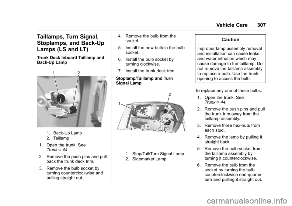
Trunk Deck Inboard Taillamp andBack-Up Lamp
1. Back-Up Lamp
2. Taillamp
1. Open the trunk. SeeTr u n k044.
2. Remove the push pins and pullback the trunk deck trim.
3. Remove the bulb socket byturning counterclockwise andpulling straight out.
4. Remove the bulb from thesocket.
5. Install the new bulb in the bulbsocket.
6. Install the bulb socket byturning clockwise.
7. Install the trunk deck trim.
Stoplamp/Taillamp and TurnSignal Lamp
1. Stop/Tail/Turn Signal Lamp
2. Sidemarker Lamp
Caution
Improper lamp assembly removal
and installation can cause leaks
and water intrusion which may
cause damage to the taillamp. Do
not remove the taillamp assembly
to replace a bulb. Use the trunk
opening to access the bulb.
To r e p l a c e a n y o n e o f t h e s e b u l b s :
1. Open the trunk. SeeTr u n k044.
2. Remove the push pins and pullthe trunk trim away from thetaillamp assembly.
3. Remove three hex-nuts fromeach stud.
4. Remove the lamp by pulling itstraight back.
5. Remove the bulb socket fromthe taillamp assembly byturning it counterclockwise.
6. Remove the bulb from thesocket by turning the bulbcounterclockwise one-quarterturn and pulling it straight out.
Page 309 of 419
Chevrolet Malibu Owner Manual (GMNA-Localizing-U.S./Canada/Mexico-10122664) - 2017 - crc - 5/23/16
308 Vehicle Care
7. Install a new bulb into thesocket.
8. Install the bulb socket into thetaillamp assembly by turning itclockwise.
9. Install the trunk trim, hex nuts,and push pins.
Taillamps, Turn Signal,
Stoplamps, and Back-Up
Lamps (LTZ)
Caution
Improper lamp assembly removal
and installation can cause leaks
and water intrusion which may
cause damage to the taillamp. Do
not remove the taillamp assembly
to replace a bulb. Use the trunk
opening to access the bulb.
The stoplamp/taillamp and trunkdeck inboard taillamp are LEDs. Toreplace, see your dealer.
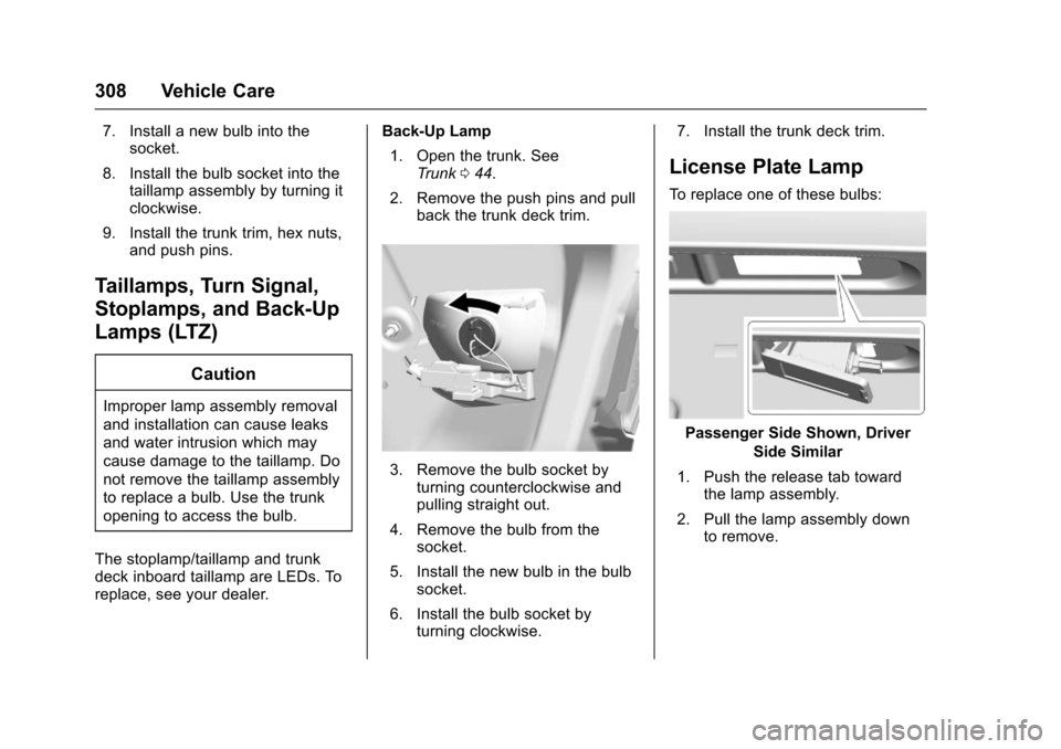
Back-Up Lamp
1. Open the trunk. SeeTr u n k044.
2. Remove the push pins and pullback the trunk deck trim.
3. Remove the bulb socket byturning counterclockwise andpulling straight out.
4. Remove the bulb from thesocket.
5. Install the new bulb in the bulbsocket.
6. Install the bulb socket byturning clockwise.
7. Install the trunk deck trim.
License Plate Lamp
To r e p l a c e o n e o f t h e s e b u l b s :
Passenger Side Shown, Driver
Side Similar
1. Push the release tab towardthe lamp assembly.
2. Pull the lamp assembly downto remove.
Page 310 of 419
Chevrolet Malibu Owner Manual (GMNA-Localizing-U.S./Canada/Mexico-10122664) - 2017 - crc - 5/23/16
Vehicle Care 309
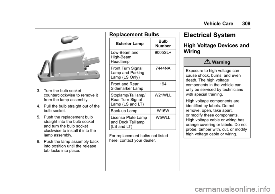
3. Turn the bulb socketcounterclockwise to remove itfrom the lamp assembly.
4. Pull the bulb straight out of thebulb socket.
5. Push the replacement bulbstraight into the bulb socketand turn the bulb socketclockwise to install it into thelamp assembly.
6. Push the lamp assembly backinto position until the releasetab locks into place.
Replacement Bulbs
Exterior LampBulbNumber
Low-Beam andHigh-BeamHeadlamp
9005SL+
Front Turn SignalLamp and ParkingLamp (LS Only)
7444NA
Front and RearSidemarker Lamp194
Stoplamp/Taillamp/Rear Turn SignalLamp (LS and LT)
W21WLL
Back-up Lamp W16W
License Plate Lampand Deck Taillamp(LS and LT)
W5WLL
For replacement bulbs not listedhere, contact your dealer.
Electrical System
High Voltage Devices and
Wiring
{Warning
Exposure to high voltage can
cause shock, burns, and even
death. The high voltage
components in the vehicle can
only be serviced by technicians
with special training.
High voltage components are
identified by labels. Do not
remove, open, take apart,
or modify these components.
High voltage cable or wiring has
orange covering or labels. Do not
probe, tamper with, cut, or modify
high voltage cable or wiring.
Page 342 of 419
Chevrolet Malibu Owner Manual (GMNA-Localizing-U.S./Canada/Mexico-10122664) - 2017 - crc - 5/23/16
Vehicle Care 341
Tire Sealant
Read and follow the safe handlinginstructions on the label adhered tothe tire sealant canister (4).
Check the tire sealant expirationdate on the tire sealant canister.The tire sealant canister (4) shouldbe replaced before its expirationdate. Replacement tire sealantcanisters are available at your localdealer.
There is only enough sealant to sealone tire. After usage, the tire sealantcanister must be replaced.
Using the Tire Sealant and
Compressor Kit to Temporarily
Seal and Inflate a
Punctured Tire
When using the tire sealant andcompressor kit during coldtemperatures, warm the kit in aheated environment for five minutes.This will help to inflate the tirefaster.
If a tire goes flat, avoid further tireand wheel damage by driving slowlyto a level place. Turn on the hazardwarning flashers. SeeHazardWarning Flashers0166.
SeeIf a Tire Goes Flat0338forother important safety warnings.
Do not remove any objects thathave penetrated the tire.
1. Remove the tire sealantcanister (4) and compressorfrom its storage location. SeeStoring the Tire Sealant andCompressor Kit0346.
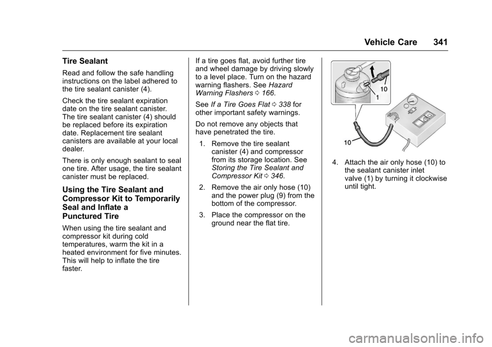
2. Remove the air only hose (10)and the power plug (9) from thebottom of the compressor.
3. Place the compressor on theground near the flat tire.
4. Attach the air only hose (10) tothe sealant canister inletvalve (1) by turning it clockwiseuntil tight.