2017 BMW 6 SERIES GRAN COUPE ignition
[x] Cancel search: ignitionPage 149 of 261
If active, the displayed speed is stored and the
vehicle reaches the stored speed when the
road is clear.▷Each time the rocker switch is pressed to
the point of resistance, the desired speed
increases or decreases by approx.
1 mph/1 km/h.▷Each time the rocker switch is pressed
past the point of resistance, the desired
speed increases or decreases by a maxi‐
mum of 5 mph/10 km/h.
The maximum speed that can be set de‐
pends on the vehicle.▷Pressing the rocker switch to the resist‐
ance point and holding it accelerates or de‐
celerates the vehicle without requiring
pressure on the accelerator pedal.
After the rocker switch is released, the ve‐
hicle maintains its final speed. Pressing the
switch beyond the resistance point causes
the vehicle to accelerate more rapidly.
Continuing cruise control
General information
An interrupted cruise control can be continued
by calling up the stored speed.
In the following cases, the stored speed value
is deleted and cannot be called up again:
▷When the system is switched off.▷When the ignition is switched off.
Information
Make sure that the difference between current
speed and stored speed is not too large before
calling up the stored speed. Otherwise, unin‐
tentional braking or accelerating may occur.
Calling up stored speed Press button.
The stored speed is reached and maintained.
Displays in the instrument cluster
Indicator lamp Depending on how the vehicle is equip‐
ped, the indicator lamp in the instru‐
ment cluster indicates whether the sys‐
tem is switched on.
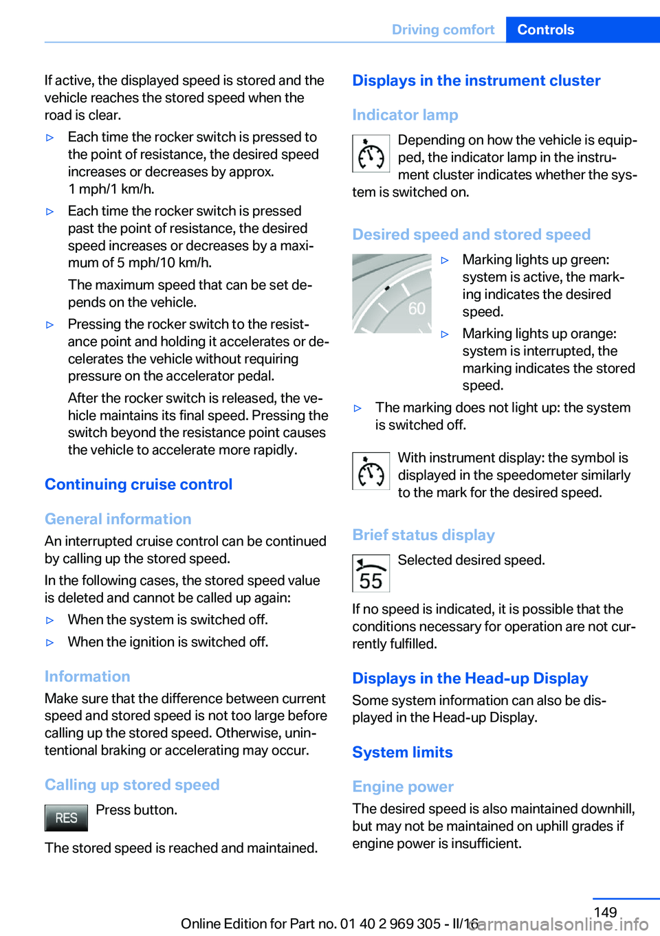
Desired speed and stored speed▷Marking lights up green:
system is active, the mark‐
ing indicates the desired
speed.▷Marking lights up orange:
system is interrupted, the
marking indicates the stored
speed.▷The marking does not light up: the system
is switched off.
With instrument display: the symbol is
displayed in the speedometer similarly
to the mark for the desired speed.
Brief status display Selected desired speed.
If no speed is indicated, it is possible that the
conditions necessary for operation are not cur‐
rently fulfilled.
Displays in the Head-up Display
Some system information can also be dis‐
played in the Head-up Display.
System limits
Engine power The desired speed is also maintained downhill,
but may not be maintained on uphill grades if
engine power is insufficient.
Seite 149Driving comfortControls149
Online Edition for Part no. 01 40 2 969 305 - II/16
Page 161 of 261

▷If a turn signal has been actuated contrary
to the desired side for parking.▷When switching to another function on the
Control Display.
A Check Control message is displayed.
Resume An interrupted parking procedure can be con‐
tinued if needed.
Reactivate the parking assistant, refer to
page 159, and follow the instructions on the
Control Display.
Switching off The system can be deactivated as follows:
▷Press park assistance button.▷Switching off the ignition.
System limits
Information WARNING
The system can react incorrectly or not
at all due to the system limits. There is risk of
accidents or risk of property damage. Observe
the information regarding the system limits
and actively intervene, if needed.◀
No parking assistance
The parking assistant does not offer assis‐
tance in the following situations:
▷In tight curves.
Functional limitations
The system may not be fully functional in the
following situations:
▷On bumpy road surfaces such as gravel
roads.▷On slippery ground.▷On steep uphill or downhill grades.▷With accumulations of leaves/snow in the
parking space.▷With ditches or edges, for example an edge
of a port.
Limits of ultrasonic measurement
Ultrasonic measuring might not function under
the following circumstances:
▷For small children and animals.▷For persons with certain clothing, for ex‐
ample coats.▷With external interference of the ultra‐
sound, for example from passing vehicles
or loud machines.▷When sensors are dirty, iced over, dam‐
aged or out of position.▷Under certain weather conditions such as
high relative humidity, rain, snowfall, ex‐
treme heat or strong wind.▷With tow bars and trailer couplings of other
vehicles.▷With thin or wedge-shaped objects.▷With moving objects.▷With elevated, protruding objects such as
ledges or cargo.▷With objects with corners and sharp edges.▷With objects with a fine surface structure
such as fences.▷For objects with porous surfaces.▷If cargo protrudes.
Low objects already displayed, for example,
curbs, can move into the blind area of the sen‐
sors before or after a continuous tone sounds.
It can happen that parking spaces are detected
that are not suitable or suitable parking spaces
are not detected.
Malfunction
A Check Control message is displayed.
The parking assistant failed. Have the system
checked.
Seite 161Driving comfortControls161
Online Edition for Part no. 01 40 2 969 305 - II/16
Page 164 of 261

Press the left or right side of the but‐
ton: decrease or increase intensity.
The selected intensity is shown on the display
of the automatic climate control.
Automatic recirculated-air control/
recirculated-air mode
You may respond to unpleasant odors or pollu‐
tants in the immediate environment by tempo‐
rarily suspending the supply of outside air. The
system then recirculates the air currently
within the vehicle.
Press button repeatedly to select an
operating mode:▷LEDs off: outside air flows in continuously.▷Left LED on, automatic recirculated-air
control: a sensor detects pollutants in the
outside air and shuts off automatically.▷Right LED on, recirculated-air mode: the
supply of outside air into the vehicle is per‐
manently blocked.
With constant recirculated-air mode, the air
quality in the car's interior deteriorates and the
fogging of the windows increases.
If the windows are fogged over, switch off the
recirculated-air mode and press the AUTO
button on the driver's side to utilize the con‐
densation sensor. Make sure that air can flow
to the windshield.
Air flow, manual To manually adjust air flow turn off AUTO pro‐
gram first.
Press the left or right side of the but‐
ton: decrease or increase air flow.
The selected air flow is shown on the display of
the automatic climate control.
The air flow of the automatic climate control
may be reduced automatically to save battery
power.
Manual air distribution
Press button repeatedly to select a
program:▷Upper body region.▷Upper body region and floor area.▷Floor area.▷Windows and floor area.▷Windows, upper body region, and floor
area.▷Windows: driver's side only.▷Windows and upper body region.
If the windows are fogged over, press the
AUTO button on the driver's side to utilize the
condensation sensor.
SYNC program The current settings on the driver's
side for temperature, air flow, air distri‐
bution, and AUTO program are transferred to the front passenger side and to the left and
right rear.
The program is also switched off if the settings
on the front passenger side or in the rear are
changed.
Residual heat The heat stored in the engine is used to heat
the interior.
Functional requirement
▷Up to 15 minutes after switching off the
engine.▷Warm engine.▷The battery is sufficiently charged.▷External temperature below 77 ℉/25 ℃.
The availability of the function is shown on the
display of the automatic climate control.
Switching on
1.Switching off the ignition.Seite 164ControlsClimate control164
Online Edition for Part no. 01 40 2 969 305 - II/16
Page 165 of 261
2. Press the right side of the button
on the driver's side.
The symbol appears on the automatic cli‐
mate Control Display.
The interior temperature, air flow and air distri‐
bution can be adjusted with the ignition
switched on.
Switching off
At the lowest fan speed, press the left side of
the button on the driver's side.
The symbol on the display of the automatic
climate control flashes.
Defrosts windows and removes
condensation
Press button.
Ice and condensation are quickly re‐
moved from the windshield and the front side
windows.
For this purpose, point the side vents onto the
side windows as needed.
Adjust air flow with the program active.
If the windows are fogged over, you can also
switch on the cooling function or press the AUTO button to utilize the condensation sen‐
sor.
Rear window defroster Press button.
The rear window defroster switches
off automatically after a certain period of time.
Microfilter/activated-charcoal filter
The microfilter removes dust and pollen from
the incoming air.
The activated-charcoal filter removes gaseous
pollutants from the outside air that enters the
vehicle.
This combined filter should be replaced during
maintenance, refer to page 226, of the vehicle.
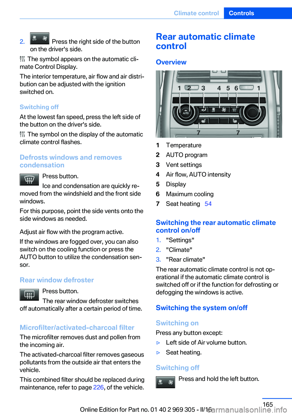
Rear automatic climate
control
Overview1Temperature2AUTO program3Vent settings4Air flow, AUTO intensity5Display6Maximum cooling7Seat heating 54
Switching the rear automatic climate
control on/off
1."Settings"2."Climate"3."Rear climate"
The rear automatic climate control is not op‐
erational if the automatic climate control is
switched off or if the function for defrosting or
defogging the windows is active.
Switching the system on/off
Switching on Press any button except:
▷Left side of Air volume button.▷Seat heating.
Switching off
Press and hold the left button.
Seite 165Climate controlControls165
Online Edition for Part no. 01 40 2 969 305 - II/16
Page 169 of 261
Interior equipmentVehicle features and optionsThis chapter describes all standard, country-
specific and optional features offered with the
series. It also describes features that are not
necessarily available in your car, e. g., due to
the selected options or country versions. This
also applies to safety-related functions and
systems. The respectively applicable country
provisions must be observed when using the
respective features and systems.
Universal Integrated Remote Control
The concept The Universal Integrated Remote Control can
operate up to 3 functions of remote-controlled
systems such as garage door drives or lighting
systems. The Universal Integrated Remote
Control replaces up to 3 different hand-held
transmitters. To operate the remote control,
the buttons on the interior mirror must be pro‐
grammed with the desired functions. The
hand-held transmitter for the particular system
is required in order to program the remote con‐
trol.
Before selling the vehicle, delete the stored
functions for the sake of security.
Information WARNING
Body parts can be jammed when operat‐
ing remote-controlled systems, e.g., the ga‐
rage door, using the integrated universal re‐
mote control. There is a risk of injury or risk of
property damage. Make sure that the area of
movement of the respective system is clear
during programming and operation. Also followthe safety instructions of the hand-held trans‐
mitter.◀
Compatibility If this symbol is printed on the packag‐
ing or in the owner's manual of the sys‐
tem to be controlled, the system is
generally compatible with the Universal Inte‐
grated Remote Control.
If you have any questions, please contact:▷A dealer’s service center or another quali‐
fied service center or repair shop.▷www.homelink.com on the Internet.
HomeLink is a registered trademark of Gentex
Corporation.
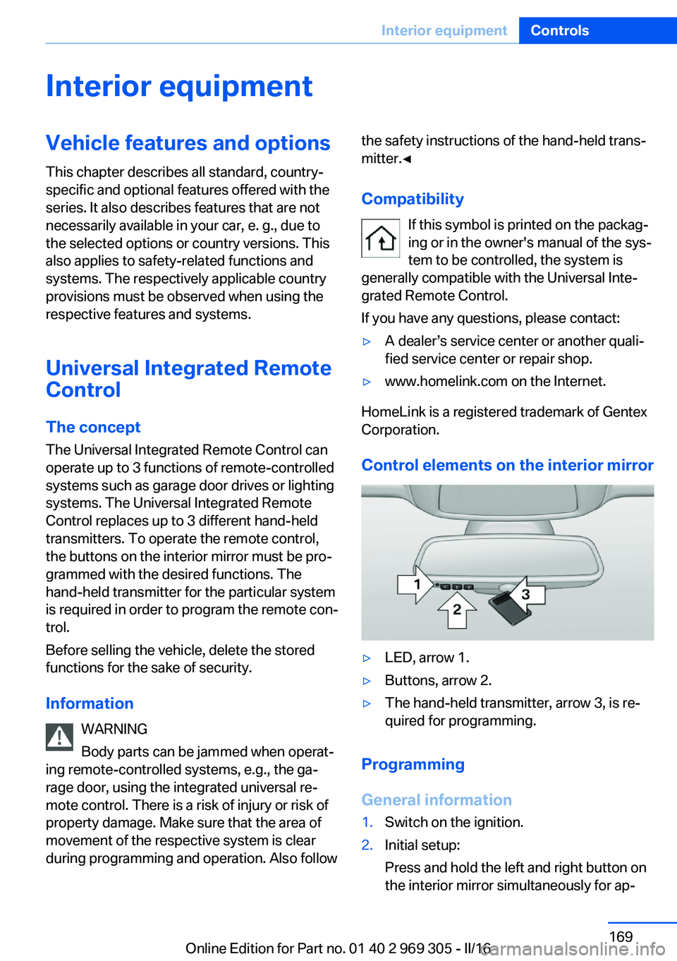
Control elements on the interior mirror
▷LED, arrow 1.▷Buttons, arrow 2.▷The hand-held transmitter, arrow 3, is re‐
quired for programming.
Programming
General information
1.Switch on the ignition.2.Initial setup:
Press and hold the left and right button on
the interior mirror simultaneously for ap‐Seite 169Interior equipmentControls169
Online Edition for Part no. 01 40 2 969 305 - II/16
Page 170 of 261
proximately 20 seconds until the LED on
the interior mirror flashes. This erases all
programming of the buttons on the interior
mirror.3.Hold the hand-held transmitter for the sys‐
tem to be controlled approx. 1 to 3 in‐
ches/2.5 to 8 cm away from the buttons of
the interior mirror. The required distance
depends on the manual transmitter.4.Simultaneously press and hold the button
of the desired function on the hand-held
transmitter and the button to be program‐
med on the interior mirror. The LED on the
interior mirror will begin flashing slowly.5.Release both buttons as soon as the LED
flashes more rapidly. The LED flashing
faster indicates that the button on the inte‐
rior mirror has been programmed.
If the LED does not flash faster after at
least 60 seconds, change the distance be‐
tween the interior mirror and the hand-held
transmitter and repeat the step. Several
more attempts at different distances may
be necessary. Wait at least 15 seconds be‐
tween attempts.
Canada: if programming with the hand-
held transmitter was interrupted, hold
down the interior mirror button and repeat‐
edly press and release the hand-held
transmitter button for 2 seconds.6.To program other functions on other but‐
tons, repeat steps 3 to 5.
The systems can be controlled using the inte‐
rior mirror buttons.
Special feature of the alternating-code wireless system
If you are unable to operate the system after
repeated programming, please check if the
system to be controlled features an alternat‐
ing-code radio system.
Read the system's owner's manual, or press
the programmed button on the interior mirror
longer. If the LED on the interior mirror starts
flashing rapidly and then stays lit constantly for
2 seconds, the system features an alternating-
code radio system. Flashing and continuous il‐
lumination of the LED will repeat for approxi‐
mately 20 seconds.
For systems with an alternating-code radio
system, the universal remote control and the
system also have to be synchronized.
Please read the owner's manual to find out
how to synchronize the system.
Synchronizing is easier with the aid of a sec‐
ond person.
Synchronizing the universal remote control
with the system:1.Park the vehicle within range of the re‐
mote-controlled system.2.Program the relevant button on the interior
mirror as described.3.Locate and press the synchronizing button
on the system being programmed. You
have approx. 30 seconds for the next step.4.Hold down the programmed button on the
interior mirror for approximately 3 seconds
and then release it. If necessary, repeat this
step up to three times in order to finish
synchronization. Once synchronization is
complete, the programmed function will be
carried out.
Reprogramming individual buttons
1.Switch on the ignition.2.Press and hold the interior mirror button to
be programmed.3.As soon as the interior mirror LED starts
flashing slowly, hold the hand-held trans‐
mitter for the system to be controlled ap‐
prox. 1 to 3 inches/2.5 to 8 cm away from
the buttons of the interior mirror. The re‐
quired distance depends on the manual
transmitter.Seite 170ControlsInterior equipment170
Online Edition for Part no. 01 40 2 969 305 - II/16
Page 171 of 261
4.Likewise, press and hold the button of the
desired function on the hand-held trans‐
mitter.5.Release both buttons as soon as the inte‐
rior mirror LED flashes more rapidly. The
LED flashing faster indicates that the but‐
ton on the interior mirror has been pro‐
grammed. The system can then be con‐
trolled by the button on the interior mirror.
If the LED does not flash faster after at
least 60 seconds, change the distance and
repeat the step. Several more attempts at
different distances may be necessary. Wait
at least 15 seconds between attempts.
Canada: if programming with the hand-
held transmitter was interrupted, hold
down the interior mirror button and repeat‐
edly press and release the hand-held
transmitter button for 2 seconds.
Controls
WARNING
Body parts can be jammed when operat‐
ing remote-controlled systems, e.g., the ga‐
rage door, using the integrated universal re‐
mote control. There is a risk of injury or risk of
property damage. Make sure that the area of
movement of the respective system is clear
during programming and operation. Also follow
the safety instructions of the hand-held trans‐
mitter.◀
The system, such as the garage door, can be
operated using the button on the interior mirror
while the engine is running or when the ignition is started. To do this, hold down the button
within receiving range of the system until the
function is activated. The interior mirror LED
stays lit while the wireless signal is being
transmitted.
Deleting stored functions Press and hold the left and right button on the
interior mirror simultaneously for approxi‐
mately 20 seconds until the LED flashes rap‐
idly. All stored functions will be deleted. The
functions cannot be deleted individually.
Sun visor Glare shieldFold the sun visor down or up.
Vanity mirror A vanity mirror is located in the sun visor be‐
hind a cover. When the cover is opened, the
mirror lighting switches on.
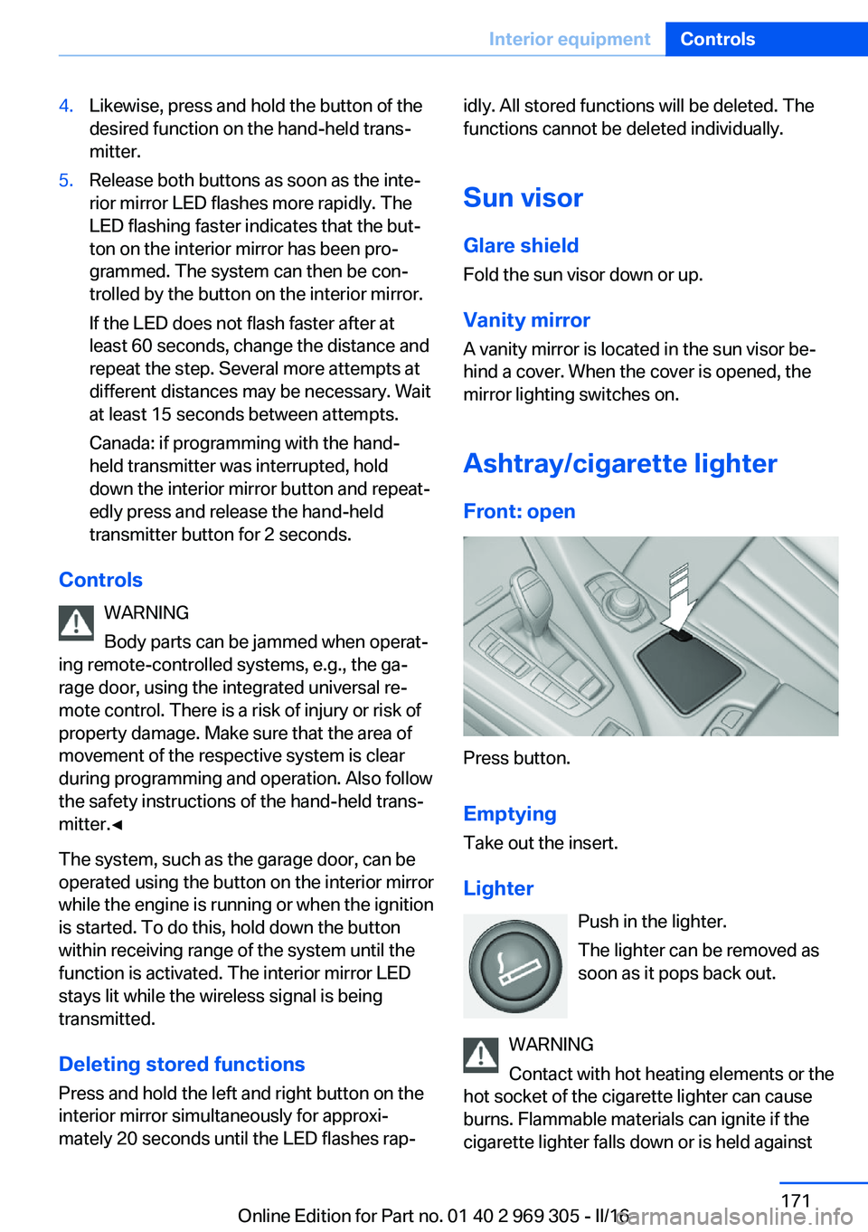
Ashtray/cigarette lighterFront: open
Press button.
Emptying Take out the insert.
Lighter Push in the lighter.
The lighter can be removed as
soon as it pops back out.
WARNING
Contact with hot heating elements or the
hot socket of the cigarette lighter can cause
burns. Flammable materials can ignite if the
cigarette lighter falls down or is held against
Seite 171Interior equipmentControls171
Online Edition for Part no. 01 40 2 969 305 - II/16
Page 172 of 261
the respective objects. There is risk of fire and
injuries. Hold the cigarette lighter on its handle.
Make sure that children do not use the ciga‐
rette lighter and do not burn themselves, e.g.,
by carrying the remote control along when ex‐
iting the vehicle.◀
ATTENTION
If metal objects fall into the socket, they
can cause a short circuit. There is a risk of
damage to property. Replace the cigarette
lighter or socket cover again after using the
socket.◀
Connecting electrical
devices
Information ATTENTION
Battery chargers for the vehicle battery
can work with high voltages and currents,
which means that the 12 volt on-board net‐
work can be overloaded or damaged. There is
a risk of damage to property. Only connect
battery chargers for the vehicle battery to the
starting aid terminals in the engine compart‐
ment.◀
ATTENTION
If metal objects fall into the socket, they
can cause a short circuit. There is a risk of
damage to property. Replace the cigarette
lighter or socket cover again after using the
socket.◀
Sockets
General information
The lighter socket can be used as a socket for
electrical equipment while the engine is run‐
ning or when the ignition is switched on.Information
The total load of all sockets must not exceed
140 watts at 12 volts.
Do not damage the socket by using non-com‐
patible connectors.
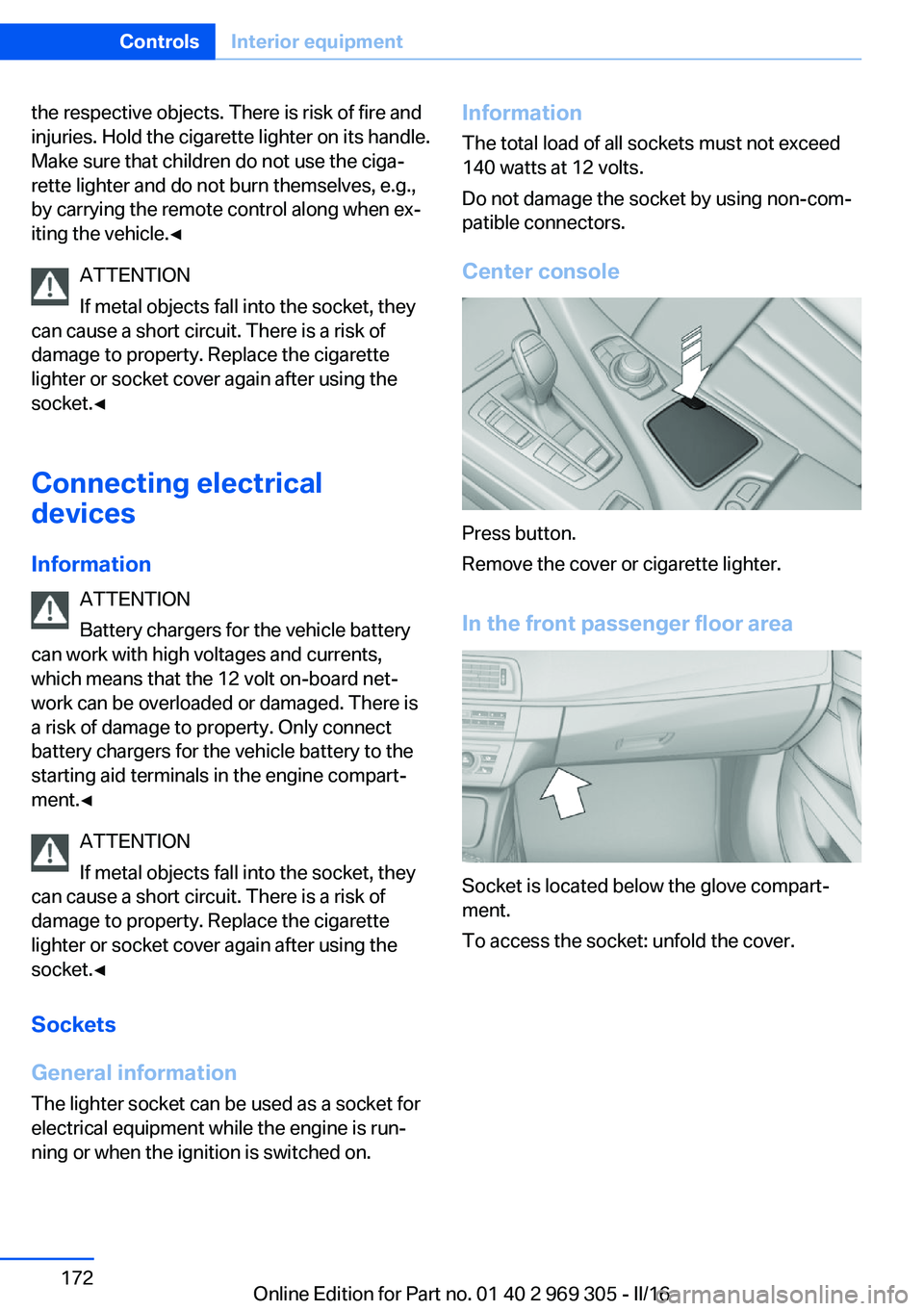
Center console
Press button.
Remove the cover or cigarette lighter.
In the front passenger floor area
Socket is located below the glove compart‐
ment.
To access the socket: unfold the cover.
Seite 172ControlsInterior equipment172
Online Edition for Part no. 01 40 2 969 305 - II/16