2017 AUDI TT ROADSTER towing
[x] Cancel search: towingPage 4 of 314

Table of content s
About this Owne r's Manual . .. .. .
5
Cockpi t . . . . . . . . . . . . . . . . . . . . . . . . . . . 6
Cockpit overview . . . . . . . . . . . . . . . . . 6
Controls at a glance . . . . . . . . . . . . . . . . . . 6
Instruments and indicator lights 8
Instruments . . . . . . . . . . . . . . . . . . . . . . . . 8
Indicator lights . . . . . . . . . . . . . . . . . . . . . 9
On-Board Diagnostic system (OBD) . . . . .
17
Drive r information system . . . . . . 19
Overview . . . . . . . . . . . . . . . . . . . . . . . . . . . 19
M ultifunction steering wheel plus . . . . . . 20
Mu ltifunction steering wheel . . . . . . . . . . 22
Tachometer . . . . . . . . . . . . . . . . . . . . . . . . 23
Odometer . . . . . . . . . . . . . . . . . . . . . . . . . . 23
On-board computer . . . . . . . . . . . . . . . . . . 23
Start ing and driving . . . . . . . . . . . . . 24
Opening and clo sing ........... . .
Cent ral lock ing .... ........... .... .. . 24
24
L uggage compa rtment lid . . . . . . . . . . . . . 29
P ower w indow . . . . . . . . . . . . . . . . . . . . . . 30
Garage doo r opener (Home link) . . . . . . . .
3 1
Power top . . . . . . . . . . . . . . . . . . . . . . . . 34
P ower top . . . . . . . . . . . . . . . . . . . . . . . . . . 34
Wind deflector . . . . . . . . . . . . . . . . . . . . . . 36
Power top emergency operation . . . . . . . . 37
Ligh ts and Vi sion . . . . . . . . . . . . . . . . . 39
Exterior lighting . . . . . . . . . . . . . . . . . . . . . 39
Interior lighting . . . . . . . . . . . . . . . . . . . . .
41
V1s1on . . . . . . . . . . . . . . . . . . . . . . . . . . . . . 42
W indshield wipers . . . . . . . . . . . . . . . . . . . 43
Dig ital compass . . . . . . . . . . . . . . . . . . . . . 45
Seats and storage ................ 47
General information . . . . . . . . . . . . . . . . . 47
Front seats . . . . . . . . . . . . . . . . . . . . . . . . . 47
Ashtray . . . . . . . . . . . . . . . . . . . . . . . . . . . . 48
Cigarette lighter and socket . . . . . . . . . . . 48
S to rage . . . . . . . . . . . . . . . . . . . . . . . . . . . . 49
L uggage compartment . . . . . . . . . . . . . . . 5 0
2
Warm and cold . . . . . . . . . . . . . . . . . . . 52
Climate contro l system . . . . . . . . . . . . . . . 52
Dr1v1ng ... .. .. .. .. .. .. .. .. .... ... . .
Genera l information .. ... . .. .... ... . .
Steering . ... .. .. .. .. ... .. ..... ... . .
Start ing and stopping the engine
Electromechanical parking brake ...... .
Start ing from a stop .. ... ....... ... . .
Automat ic transmission ....... ..... . .
Tra ile r towing ...................... .
Driver assistance .............. .. .
Assist ............................ .
Electronic speed lim iter ..... ....... .. .
Speed warning sy stem . .. ........... . .
Cruise cont rol sys tem
Audi active lane assist ... . ... .... ... . .
Audi side assist . ... ... .. .. ..... ... . .
Audi drive select (drive settings) ... ... . .
Park ing sy stem s
Genera l information
Rear parking system
Parking system plus . .. .. ........... . .
Rearv iew camera . .. .. .............. .
Adjusting the d isplay and the warning
tones ........ ... ................ .. .
Er ror messages .. .. .. ... ....... ... . .
Intelligent Technology ......... .
Electron ic stabilization control (ESC) .. . .
B rakes ............................ .
El ectrome chanical steering .......... .
A ll wheel drive (quattro) .. .. ..... ... . .
Rear spoiler ... .. .. .. ... .. ..... ... . .
Energy management .. .. . ... .... ... . .
Information about data recorded by
57
57
59
59
62
63
63
71
72
72
72
72
72
74
76
79
82
82
83
83
84
86
86
88
88 89
91
91
92
93
vehicle control modules . . . . . . . . . . . . . . 94
Infotainment system . . . . . . . . . . . . 96
Multi Media Inte rface . . . . . . . . . . . . 96
Traffic safety information . . . . . . . . . . . . . 96
Introduction . . . . . . . . . . . . . . . . . . . . . . . . 96
MMI On/Off knob with joystick function . . 96
MM I ope ration . . . . . . . . . . . . . . . . . . . . . . 97
MM I touch . . . . . . . . . . . . . . . . . . . . . . . . . 98
Operat ing . . . . . . . . . . . . . . . . . . . . . . . . . .
101
Page 36 of 314

Power top
Power top
Power top
General information
The power top opens and closes automatically .
When open, the power top is stored completely
in the power top compartment. The power top
can be opened or closed at speeds up to 30 mph
(SO km/h).
Under normal conditions, the power top is wind
and waterproof. In rare cases, small droplets of
water may form under extreme weather condi
tions such as torrential or prolonged rain. That is
normal and no cause for concern.
Follow the care instructions to keep the power
top free of leaks and to maintain its appearance
~ page 266, Core and cleaning. Also observe the
following:
- Open and stow the power top only when it is
clean and dry . Sharp-edged dirt particles can
cause damage to the rear window and the pow
er top . Stowing the power top when it is damp
can create imprints in it, and if it is left that
way for long periods of time, mildew and other
damage can form .
- Do not leave the power top open for several weeks or the creases in it may become discol
ored.
- Remove ice and snow before opening the power
top. Do not use any sharp edged objects to re move ice and snow or the power top could be
scratched or damaged . The rear window may be
cleared with a standard ice scraper .
- Do not open the power top when the tempera
ture is below 32 °F (0 °C). The fabric in the
power top loses elasticity in sub-zero tempera
tu res .
34
Opening and closing the power top
Fig. 28 Center conso le: power top sw itch
Opening/closing the power top
.,. Switch on the ignition.
.,. To open or close the power top, pull/press and
hold the button during the entire process.
Opening/closing the power top using the
one-touch function
.,. Switch on the ignition .
.,. To open/close the power top all the way, briefly
pull/press the power top switch. It is not neces
sary to hold the switch. The one-touch function
is only available at speeds between 4 mph (6
km/h) and 30 mph (SO km/h).
The status of the power top is shown in the in
strument cluster when operating the power top
switch.
A message will appear in the instrument cluster
if the power top cannot be opened or closed
~ page 35.
A WARNING
-When operating the power top, make sure
the function is not affected by wind or other
factors and that it does not interfere with
other drivers.
- Never drive when the power top is not
locked correctly. The wind from driving
could cause the power top to open. This can
result in injuries and damage to the vehicle .
- Make sure no one will be injured by the pow
er top supports and other moving compo
nents when opening and closing the top.
Page 43 of 314
CD
CD
.... N
" N .... 0 r--. V, co
Canada models: this function cannot be switched
off . They activate automatically each time the ig
n ition is switched on . This menu item is shown
with a "gray background".
Coming home, Leaving home
The coming home function illuminates the area
outside the vehicle when you turn the ignition off
and open the driver's door. To switch on the func
tion, se lect
Entry/exit lighting.
The leaving home illumi nates the area outs ide
the vehicle when you unlock the vehicle . To
switch on the function, select
Entry/exit light
ing .
The coming home and leaving home funct ions
only operate when it is dark and the light switch
is in the
AUTO position.
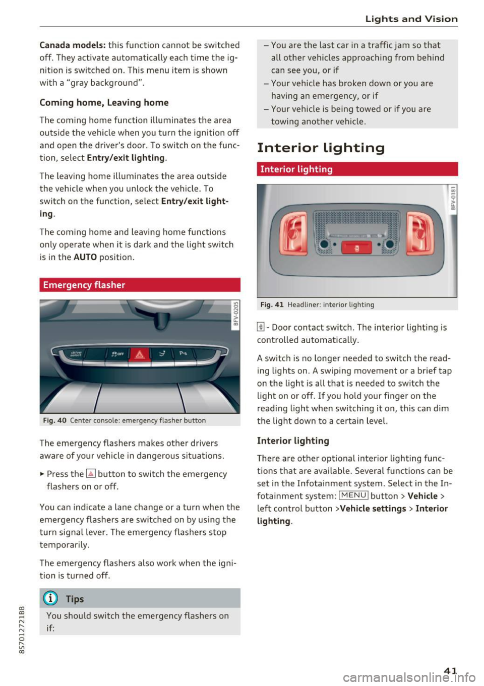
Emergency flasher
Fig. 40 Center conso le: emergency f las her button
The emergency flashers makes other drivers
aware of yo ur vehicle in dangerous situations .
.. Press the
[!J button to switch the emergency
flashers on or off.
You can indicate a lane change or a turn when the
emergency flas hers are switched on by using the
turn signal lever. The eme rgency flashers s top
temporarily.
The emergency flashers also wo rk when the igni
tion is turned off.
(D} Tips
You should sw itch the emergency flashers on
if:
Lights and V ision
-You are the last ca r in a traffic jam so that
all other vehicles approaching from behind
can see you, or i f
- Your vehicle has broken down or yo u are
having an emergency, or if
- Your vehicle is be ing towed o r if you are
towing another vehicle .
Interior lighting
Interior lighting
Fig. 41 Headliner: interior lighti ng
[!l-Door contact switch. The interior lighting is
controlled automatically.
A switch is no longer needed to switch the read
ing lights on.
A swiping movement or a brief tap
on the light is all that is needed to switch the
light on or off. If you hold your finger on the
read ing light when switching it on, this can d im
the light down to a certain level.
Interior lighting
There are other opt ional interior lighting func
tions that are available . Several functions can be
set in the Infotainment system. Select in the In
fotainment system:
I MENU I button> Vehicle>
left control button >Vehicle settings > Interior
lighting .
41
Page 52 of 314
Sea ts and stor age
Storage compartment between the seat
backrests
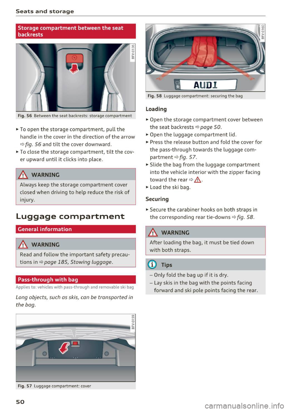
Fig . 56 Between th e seat backrests: storage compartment
• To open the storage compartment, pull the
handle in the cover in the direction of the ar row
r::::> fig . 56 a nd til t the cover downward.
• To close the s torage compa rtment, t ilt the cov
er upward until it clicks into place .
_& WARNING
Always keep the storage compartment cover
closed when dr iv ing to help reduce the risk of
injury.
Luggage compartment
General information
A WARNING
Read and follow the important safety precau
tions in¢
page 185, Stowing luggage.
Pass-through with bag
Applies to: vehicles with pass-through and removable s ki bag
Long objects , such as skis, can be transported in
the bag .
Fig . 57 Luggage compartme nt: cover
50
fl AUD I 1
Fig. 58 Luggage compa rtment: secu ring the bag
Loading
• Open the storage compartment cover between
the seat backrests ¢
page 50.
• Open the luggage compa rtment lid .
• Press the release button and fo ld the cove r fo r
t he pass-th rough towards the luggage com
partment ¢
fig. 57.
• Slide the bag from the luggage compartment
into the vehicle inter ior with the zipper facing
toward the rear
r::::> .&_.
• Load the ski bag.
Securing
• Secure the carabine r hooks on both straps in
the corresponding rea r tie-downs
r::::> fig . 58.
A WARNING
After loading the bag, it must be tied down
with both straps.
(I} Tips
-Only fold the bag up if it is dry.
- Lay skis in the bag with the points facing
forward and ski pole points facing the rear.
-
Page 70 of 314

Driving - The transmission can overheat and be dam
aged under certain driving and traffic condi
tions such as frequent starts, creeping for a
long time, or stop -and-go traffic. When the
@] or. indicator light turns on, stop the
vehicle at the next opportunity and let the
transmission cool
r=;, page 70 .
-Allowing the vehicle to roll when the engine
is stopped will damage the S tronic trans
mission because it is not lubricated
¢ page 286, Towing with a tow truck.
@ Tips
For safety reasons, the parking brake is re
leased automatically only when the driver's
safety belt is engaged in the buckle.
Hill descent control
The hill descent control system assists the driver
when driving down hills .
Hill descent control is ac tivated when the selec
tor lever is in the Dor S position and you press
the brake pedal. The transmission automatically
selects a gear that is suitable for the hill. Hill de
scent control tries to maintain the speed ach
ieved at the time of braking, within physical and
technical limitations.
If may still be necessary to
adjust the speed with the brakes. Because hill de
scent control cannot shift down farther than 3rd
gear, it may be necessary to shift into tiptronic
mode in very steep areas. In this case, shift man
ually into 1st or 2nd gear in tiptronic mode to
use the engine's braking force to relieve the
brakes .
Hill descent control switches off once the hill lev
els out or you press the accelerator pedal.
On vehicles with a cruise control system*
¢ page 72, hill descent control is also activated
when the speed is set.
A WARNING
Hill descent control cannot overcome physical
limitations, so it may not be able to maintain
a constant speed under all conditions. Always
be ready to apply the brakes.
68
Shifting manually (tiptronic mode)
The tiptronic mode allows the driver to shi~ the
gears manually .
Fig. 73 C enter conso le: sh ift ing ma nuall y wi th the selecto r
lever
Fig. 74 Steering whee l: ma nual shifting wit h the shift pad
dles•
Shifting with the selector lever
You can shift into tiptronic mode while stationary
and whi le driving.
.,. To shift into tiptronic mode, push the selector
lever from the D/S setting to the right in the
tiptronic shift gate. Once the transmission has
sw itched modes, the selector lever position
M
is shown in the Infotainment system display
r=;, page 64, fig. 70 . For example M4 means the
fourth gear is engaged .
.,. To shift up a gear, tap the selector lever for
ward
G) ¢ fig. 73.
.,. To shift down a gear, tap the selector lever to
back
0 .
Shifting with the shift paddles*
You can operate the shift paddles in the D/S or
M
(tiptronic shift gate) selector lever positions.
.,. To shift up one gear, tap the shift paddle
0
r=;, fig. 7 4.
Page 73 of 314
CD
CD
.... N
" N ,-I 0
" V, co
Selector lever emergency release
If the vehicle's power supply fails, the selector lever can be released in an emergency.
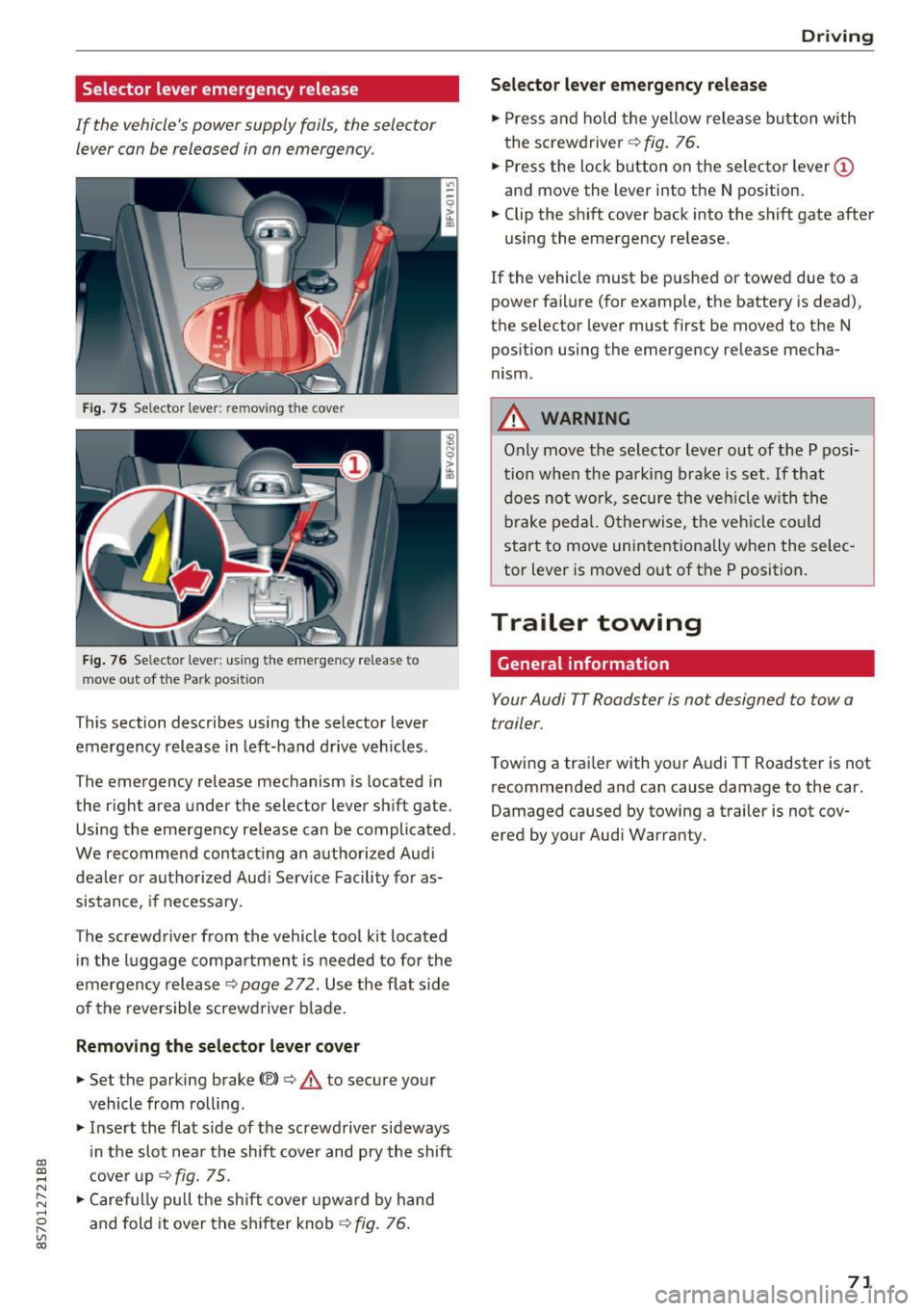
Fig . 75 Selector lever: remov ing t he cover
Fi g. 76 Selec tor lever : us ing the eme rgency re lease to
move out of t he Park pos it ion
This section describes using the selector lever
emergency release in left-hand drive veh icles .
The emergency re lease mechanism is located in
the right area under the selector lever shift gate.
Using the emergency release can be complicated.
We recommend contact ing an authorized Audi
dealer o r authorized Aud i Serv ice Facility fo r as
sistance, if necessary .
The screwdriver from the vehicle tool kit located
i n the luggage compartment is needed to for the
emergency release ¢
page 2 72. Use the flat sid e
of the revers ible screwd river b lade.
Removing the selector lever cover
.,. Set the parking brake CV)¢ A to secure your
vehicle from ro lling .
.,. In se rt the flat side of the screwdriver sideways
in the slot nea r the sh ift cover and pry the shift
c ove r up
¢fig. 75 .
.,. Caref ully pull t he shift cover upw ard by hand
and fold it over the sh ifter knob ¢
fig. 76.
Drivi ng
Selector l ever emergency release
.,. Press and hold t he ye llow release b utton with
the screwdriver ¢
fig. 76.
.,. Press the lock button on the selecto r lever
(D
and move the lever into the N position .
.,. Clip the shift cover back into the shift gate after
using the emergency re lease.
If the vehicle must be pushed or towed due to a
power failure (for example, the battery is dead),
the selector lever must first be moved to the N
pos ition using the emergency re lease mecha
nism.
A WARNING
Only move the selector lever out of the P pos i
tion when the parking bra ke is set. If that
d oes no t wo rk, secure the ve hicle w ith the
bra ke ped al. Otherwise, t he veh icle co ul d
st art to move uninte ntiona lly w hen the selec
tor lever is moved out of the P position.
Trailer towing
General information '
Your Audi TT Roadster is not designed to tow a
trailer.
Towing a trailer with you r Audi TT Roadster is not
recommended and can cause damage to the car.
Damaged caused by towing a trailer is not cov
ered by your Audi Warranty.
71
Page 187 of 314
co
co
.... N
" N .... 0
" "' c:o
A WARNING ,~
Pedals that cannot move freely can cause loss
of vehicle control and increase the risk of seri
ous injury .
- Never place any objects in the driver's foot
well. An object could get into the pedal area
and interfere w ith pedal function . In case of
sudden braking or an accident, you would
not be able to brake or accelerate!
- Always make sure that nothing can fall o r
move into the dr iver's footwe ll.
Floor mats on the driver side
Always use floor mats that can be securely at
tached to the floor mat fasteners and do not in
terfere with the free movement of the pedals .
.,. Make sure that the floor mats are properly se
cured and cannot move and interfe re with the
peda ls ¢ ,&. .
Use o nly floor mats that leave the pedal area un
obstructed and that are firmly secured so that
they cannot slip out of pos it ion . You can obtain
suitable floo r mats from yo ur au tho riz ed A ud i
Dea le r.
Floor mat fasteners are installed in your Audi.
F loor mats used in your vehicle must be attached
to these fasteners. Properly securing the floor mats w ill prevent them from sliding into posi
tions that could interfere with the pedals or im
pa ir safe operation of your veh icle in other ways .
A WARNING
Pedals that cannot move free ly can resul t in a
loss of vehicle control and increase the risk of
ser ious personal in jury.
- Always ma ke sure tha t floor mats are p rop
erly se cured.
- Never place o r insta ll floo r mats or other
floo r coverings in the ve hicle tha t cannot be
properly se cured in place to prevent them
from slipp ing and interfering with the ped
als or the ability to control the vehicle .
- Never place or inst all floo r ma ts or o ther
floo r coverings on top of a lready installed
Safe d riv ing
floor mats. Additional floor mats and other
cover ings will reduce the size of the pedal
area and interfere with the pedals.
- Always properly re insta ll and secure floor
mats that have been taken out for clean ing .
- Always make sure that objects cannot fall
into the driver footwell whi le the vehicle is
mov ing . Objects can become trapped under
the brake pedal and accelerator pedal caus i n g a loss of vehicle control.
Stowing luggage
Loading the luggage compartment
All luggage and other objects must be properly
stowed and secured in the luggage compart
ment .
Loose items in the luggage compa rtme nt can
shift suddenly , changing veh icle hand lin g charac
te ris tics. Loose i tems can a lso incre ase the risk of
serious persona l injury in a sudden veh icle ma
neuver or in a collision.
.. Distribute the load evenly in the luggage com
par tment .
.. Always p lace and properly sec ure heavy items in
the l uggage compartment as far forward as
possible .
.. Secure luggage using the t ie-downs provided
¢page 186.
A WARNING ~
Improperly stored luggage or o ther items can
f ly through the veh icle ca using se rious per
sona l injury i n the event of ha rd bra king or an
a ccident. To help reduce the risk of serio us
p ersonal injury:
- Always put objects, for example, l uggage or
o ther heavy items in the l uggage compart
ment .
- Always secure objects in the luggage com
pa rtment us ing the tie-down eyelets and
suitable st raps.
185
Page 262 of 314
Wheels
NEVER EXCEED XXX KG OR XXX
LBS"on your vehicle's placard
(tire inflation pressure label)
¢ page 256, fig. 190.
2. Determine the combined
weight of the driver and pas
sengers that will be riding in
your vehicle.
3. Subtract the combined weight
of the driver and passengers
from
"XXX" kilograms or "XXX"
pounds shown on the sticker
¢ page 256, fig. 190.
4. The resulting figure equals the
available amount of cargo and
luggage load capacity. For ex
ample, if the "XXX" amount
equals 1400 lbs and there will
be five 150 lbs passengers in
your vehicle, the amount of available cargo and luggage
load capacity is 650 lbs
(1400-750 (5
X 150) = 650 lbs)
5. Determine the combined weight of luggage and cargo
being loaded on the vehicle.
That weight may not safely ex ceed the available cargo and luggage load capacity calculat
ed in Step 4.
6. If your vehicle will be towing a
trailer, load from your trailer
will be transferred to your ve-
260
hicle. Consult this manual to
determine how this reduces
the available cargo and lug
gage load capacity of your vehi
cle.
~check the tire sidewall
(¢ page 246, fig. 188) to deter
mine the designated load rating
for a specific tire.
· Wheel bolts and rims
Wheel bolts
Wheel bolts must be clean and loosen/tighten
easily.
Rims
Rims with a bolted rim ring* or with bolted wheel
covers* consist of multiple pieces. These compo
nents were bolted together using special bolts
and a special procedure. You must not repair or
disassemble them
¢ &..
_8. WARNING
-Wheel bolts that are tightened or repaired in
correctly can become loose and result in loss
of vehicle control, which increases the risk of
an accident. For the correct tightening specifi
cation, see
¢ page 2 78, Finishing.
- Always keep the wheel bolts and the threads in the wheel hub clean and free of
grease .
- Only use wheel bolts that fit the rim.
- Always have damaged rims repaired by an
authorized Audi dealer or authorized Audi
Service Facility . Never repair or disassemble
rims yourself, because this increases the risk
of an accident .
Winter tires
Winter tires significantly improve the vehicle's
handling when driving in winter conditions . Be-
cause of their construction (width, compound, ..,.