2017 Alfa Romeo Giulia warning light
[x] Cancel search: warning lightPage 166 of 268
If the obstacle is detected in the rear left
and/or right area, a single flashing arc
will be shown in the corresponding area
on the display and the system will emit
an acoustic signal, either at frequent
intervals or constantly.
In general, the vehicle is closer to the
obstacle when a single flashing arc is
shown on the display and the acoustic
signal becomes continuous.
If several obstacles are detected
simultaneously in the rear area, the
display will show all of them, regardless
of the area in which they were detected.
The color on the display depends on
the distance from and position of the
obstacle.
It is possible to exit from the display
screen by pressing the Rotary Pad,
however, the acoustic alert will remain
active.
Fault Indication
Parking sensor faults, if any, will be
indicated when REVERSE is engaged
by a message on the instrument cluster
display. Refer to "Warning Lights And
Messages" in "Getting To Know Your
Instrument Panel".
Messages On The Display
In case of system failure, a dedicated
message appears on the instrument
cluster for about 5 seconds.Cleaning The Front Sensors:Ifthe
display shows a message requiring the
sensors to be cleaned, make sure that
the outer surface and the underside of
the rear bumper is free of debris (e.g.
snow, mud, ice, etc.). Once these areas
are clear, place the ignition in STOP
mode. Then, return it to ON mode. If
the message is still displayed, contact
an authorized dealer.
Audio System Not Available :Ifthe
display shows a message that the
audio system is not available, it means
that the acoustic signal will be emitted
by the instrument panel, and not
through the vehicles speakers.
Note: Some conditions may influence
the performance of the ParkSense
system:
Reduced sensor sensitivity could
be due to the presence of ice, snow,
mud, or thick paint on the surface of
the sensor.
The sensors may detect a false
obstacle (echo interference) due to
mechanical interference, for example
when washing the vehicle or in
extreme weather.
The signals sent by the sensors can
be altered by the presence of
ultrasonic systems (e.g. pneumatic
brake systems of trucks or pneumatic
drills) near the vehicle.
System performance can be
influenced by the position of the
sensors. For example, due to a change
in the ride setting (caused by wear to
the shock absorbers or suspension),
by changing tires, overloading the
vehicle or operations that require the
vehicle to be lowered.
Be sure not to place bumper
stickers or other adhesives over the
sensors as this will affect system
performance.
Warning!
Drivers must be careful when backing up
even when using the Parking Sensor
system. Always check carefully behind your
vehicle, and be sure to check for
pedestrians, animals, other vehicles,
obstructions, or blind spots before backing
up. You are responsible for the safety of
your surroundings and must continue to
pay attention while backing up. Failure to
do so can result in serious injury or death.
164
STARTING AND OPERATING
Page 168 of 268
Note:If the sensors detect several
front and rear obstacles, the closest
obstacle is considered. An intermittent
signal will sound if the obstacles are at
the same distance (front and rear).
When the system emits an acoustic
signal, the volume of the Connect
system, if activated, is automatically
lowered.
Indication On Display
The driver can select the type of
warning they would like to be displayed
through the Connect system. To access
the function on the main menu, select in
the following order:
1. “Settings”
2. “Driver assistance”
3. “Park Sensors”
4. “Mode”
5. “Sound-Display”
Visual Indications
The system indicates the presence of
an obstacle by displaying a single arc in
the detected areas, in relation to the
distance of the object and the position
of the vehicle.
If the obstacle is detected in the front or
rear central area, a single arc will be
displayed as the obstacle approaches,
first constant, then flashing, in addition
to an acoustic signal. If the obstacle is detected in the front or
rear left and/or right area, a single
flashing arc will be shown in the
corresponding area on the display and
the system will emit an acoustic signal,
either at frequent intervals or constantly.
If several obstacles are detected
simultaneously in the front and rear
area, the display will show all of them,
regardless of the area in which they
were detected.
In general, the vehicle is closer to the
obstacle when a single or several
flashing arcs are shown on the display
and the acoustic signal becomes
continuous. The color on the display
depends on the distance from and
position of the obstacle.
It is possible to exit from the display
screen by pressing the Rotary Pad,
however, the acoustic alert will remain
active.
Fault Indication
Parking sensor faults, if any, will be
indicated by a message on the display
on the instrument cluster. Refer to
"Warning Lights And Messages" in
"Getting To Know Your Instrument
Panel".
Messages On The Display
In case of system failure, a dedicated
message appears on the instrument
cluster for about 5 seconds.Cleaning the front or rear
sensors: If the display shows a
message requiring the sensors to be
cleaned, make sure that the outer
surface and the underside of the front
and rear bumpers are free of debris
(e.g. snow, mud, ice, etc.). Once these
areas are clear, place the ignition in
STOP mode. Then, return it to ON
mode. If the message is still displayed,
contact an authorized dealer.
Audio system not available :Ifthe
display shows a message that the
audio system is not available, it means
that the acoustic signal will be emitted
by the instrument panel, and not
through the vehicles speakers.
Note: Some conditions may influence
the performance of the ParkSense
system:
Reduced sensor sensitivity could
be due to the presence of ice, snow,
mud, or thick paint on the surface of
the sensor.
The sensors may detect a false
obstacle (echo interference) due to
mechanical interference, for example
when washing the vehicle or in
extreme weather.
The signals sent by the sensors can
be altered by the presence of
ultrasonic systems (e.g. pneumatic
brake systems of trucks or pneumatic
drills) near the vehicle.
166
STARTING AND OPERATING
Page 169 of 268
System performance can be
influenced by the position of the
sensors. For example, due to a change
in the ride setting (caused by wear to
the shock absorbers or suspension),
by changing tires, overloading the
vehicle or operations that require the
vehicle to be lowered.
Be sure not to place bumper
stickers or other adhesives over the
sensors as this will affect system
performance.
Warning!
Drivers must be careful when backing up
even when using the Parking Sensor
system. Always check carefully behind your
vehicle, and be sure to check for
pedestrians, animals, other vehicles,
obstructions, or blind spots before backing
up. You are responsible for the safety of
your surroundings and must continue to
pay attention while backing up. Failure to
do so can result in serious injury or death.
Caution!
The Parking Sensor system is only a
parking aid and it is unable to recognize
every obstacle, including small obstacles.
Parking curbs might be temporarily
detected or not detected at all. Obstacles
located above or below the sensors will not
be detected when they are in close
proximity
The vehicle must be driven slowly when
using the Parking Sensor system in order
to be able to stop in time when an obstacle
is detected. It is recommended that the
driver looks over his/her shoulder when
using the Parking Sensor system.
LANE DEPARTURE
WARNING (LDW)
SYSTEM
Description
The Lane Departure Warning system
uses a forward looking camera located
on the windshield to detect lane
markings and measure vehicle position
within the lane boundaries.
When one or both lane limits are
detected and the vehicle passes over
one without the an activated turn signal,
the system emits an acoustic signal.
If the vehicle continues to go beyond
the line of the lane without any
intervention from the driver, the
surpassed line will light up on the
display (left or right) to urge the driver to
bring the vehicle back into the limits of
the lane.
167
Page 173 of 268
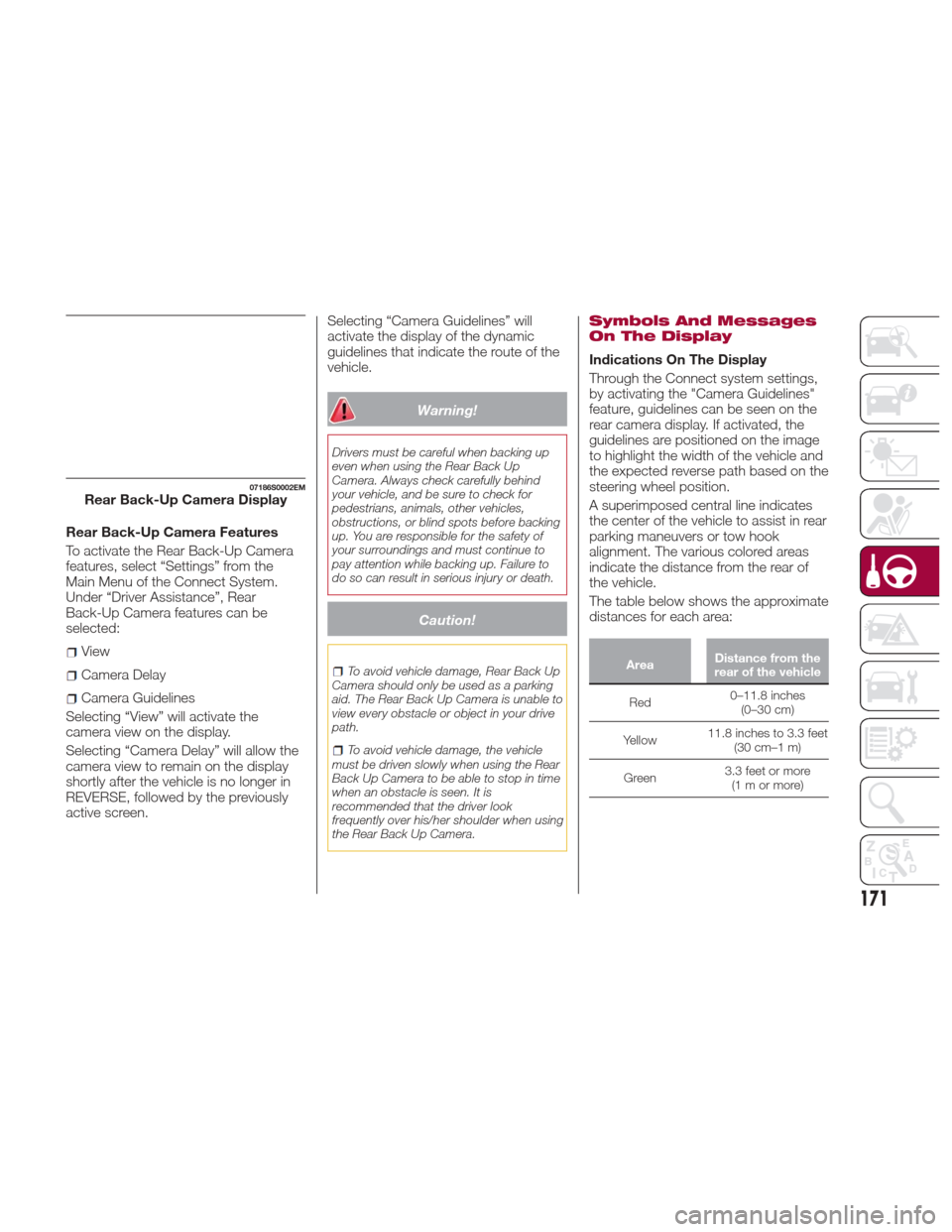
Rear Back-Up Camera Features
To activate the Rear Back-Up Camera
features, select “Settings” from the
Main Menu of the Connect System.
Under “Driver Assistance”, Rear
Back-Up Camera features can be
selected:
View
Camera Delay
Camera Guidelines
Selecting “View” will activate the
camera view on the display.
Selecting “Camera Delay” will allow the
camera view to remain on the display
shortly after the vehicle is no longer in
REVERSE, followed by the previously
active screen. Selecting “Camera Guidelines” will
activate the display of the dynamic
guidelines that indicate the route of the
vehicle.
Warning!
Drivers must be careful when backing up
even when using the Rear Back Up
Camera. Always check carefully behind
your vehicle, and be sure to check for
pedestrians, animals, other vehicles,
obstructions, or blind spots before backing
up. You are responsible for the safety of
your surroundings and must continue to
pay attention while backing up. Failure to
do so can result in serious injury or death.
Caution!
To avoid vehicle damage, Rear Back Up
Camera should only be used as a parking
aid. The Rear Back Up Camera is unable to
view every obstacle or object in your drive
path.
To avoid vehicle damage, the vehicle
must be driven slowly when using the Rear
Back Up Camera to be able to stop in time
when an obstacle is seen. It is
recommended that the driver look
frequently over his/her shoulder when using
the Rear Back Up Camera.
Symbols And Messages
On The Display
Indications On The Display
Through the Connect system settings,
by activating the "Camera Guidelines"
feature, guidelines can be seen on the
rear camera display. If activated, the
guidelines are positioned on the image
to highlight the width of the vehicle and
the expected reverse path based on the
steering wheel position.
A superimposed central line indicates
the center of the vehicle to assist in rear
parking maneuvers or tow hook
alignment. The various colored areas
indicate the distance from the rear of
the vehicle.
The table below shows the approximate
distances for each area:
Area Distance from the
rear of the vehicle
Red 0–11.8
inches
(0–30 cm)
Yellow 11.8 inches to 3.3 feet
(30 cm–1 m)
Green 3.3 feet or more
(1mormore)
07186S0002EMRear Back-Up Camera Display
171
Page 178 of 268

Max. Speed
Fuel consumption considerably
increases as speed increases. Maintain
a constant speed, avoiding
unnecessary braking and acceleration,
which cost in terms of both fuel
consumption and emissions.
Acceleration
Accelerating violently severely affects
consumption and emissions:
acceleration should be gradual and
should not exceed the maximum
torque.
Conditions Of Use
Cold Starting
Short trips and frequent cold starts will
not allow the engine to reach optimum
operating temperature. This results in a
significant increase in consumption
levels (from +15 to +30% in city driving)
and emissions.
Traffic And Road Conditions
High fuel consumption is caused by
heavy traffic, for instance when
travelling in traffic with frequent use of
low gears or in cities with many traffic
lights. Winding mountain roads and
rough road surfaces also adversely
affect consumption.
Stops In Traffic
During prolonged stops (e.g. railway
crossings) switch off the engine.
Transporting
Passengers
Warning!
It is extremely dangerous to leave
children in a parked vehicle when the
temperature outside is very high. The heat
inside the passenger compartment may
have serious, or even fatal, consequences.
Never travel in the trunk of the vehicle. In
the event of an accident, anyone inside the
trunk would be at greater risk of serious or
even fatal injury.
Ensure that all the occupants of the
vehicle wear their seat belts correctly and
that any children are positioned correctly
on the dedicated child restraint systems.
Transporting Animals
The intervention of the airbags may be
dangerous for an animal on the front
seat. It is therefore advised to arrange
animals on the rear seat inside
dedicated cages restrained by the
vehicle’s seat belts.
Keep in mind that, in the event of a
sudden braking or an accident, an
inadequately restrained animal may be
projected within the passenger
compartment, risking injury to the
animal itself and the other occupants of
the vehicle.
Exhaust Gas
Exhaust emissions are very dangerous,
and may be lethal. They contain carbon
monoxide, a colorless, odorless gas
which can cause fainting and poisoning
if inhaled.
To avoid inhaling carbon monoxide,
take the following measures:
Do not keep the engine running in
closed spaces.
If, for some reason (e.g. transporting
bulky loads), it is necessary to drive
with the trunk open, close all the
windows and run the climate control fan
at maximum speed. DO NOT activate
air recirculation mode.
Should it be necessary to stay in the
stationary vehicle with engine running,
adjust the ventilation/heating system
and operate the fan in such a way that
outside air will enter the passenger
compartment. Activate the maximum
fan speed.
Maintenance of the exhaust system
provides the best protection against
leaks of carbon monoxide into the
passenger compartment.
Should an unusual noise from the
exhaust system or the presence of
exhaust gas in the passenger
compartment be identified, or if the
underbody or rear section of the vehicle
is damaged, have the entire exhaust
system and bodywork areas checked
to identify any components which are
176
STARTING AND OPERATING
Page 181 of 268
IN CASE OF EMERGENCY
Have a flat tire or a burnt-out bulb?
At times, a problem such as these may
interfere with your driving experience.
The pages on emergencies can help
you to deal with critical situations
independently and with calm.
In an emergency, we recommend that
you call the phone number found in the
Warranty Book.
You may also consider contacting your
nearest authorized dealer.HAZARD WARNING LIGHTS . . . .180
BULB REPLACEMENT.........180
FUSES .................. .186
TIRE REPAIR KIT —
IF EQUIPPED ..............192
EMERGENCYSTARTING ......196
REFUELING IN EMERGENCY . . . .198
ENGINE OVERHEATING .......199
TOWING A DISABLED VEHICLE . .200
TOW HOOKS ..............201
ENHANCED ACCIDENT
RESPONSE SYSTEM (EARS) . . . .203
EVENT DATA RECORDER (EDR) . .203
179
Page 182 of 268
HAZARD WARNING
LIGHTS
The Hazard Warning flasher switch is
located in the switch bank below the
radio screen.Push the switch once
to turn the hazard
warning flasher on.
When the switch is
activated, all
directional turn signals
will flash on and off to warn oncoming
traffic of an emergency. Push the switch
a second time to turn the hazard
warning flashers off.
This is an emergency warning system
and it should not be used when the
vehicle is in motion. Use it when your
vehicle is disabled and is creating a
safety hazard for other motorists.
When you must leave the vehicle to
seek assistance, the hazard warning
flashers will continue to operate even
though the ignition is placed in the OFF
position.
Note:
With extended use the hazard warning
flashers may discharge your battery.
Caution!
Prolonged use of the hazard warning
flashers may discharge the vehicle’s
battery.
BULB
REPLACEMENT
General InstructionsBefore replacing a bulb, check the
contacts for oxidation.
Replace blown bulbs with others of
the same type and power.
After replacing a headlight bulb,
always check its alignment.
When a light is not working, check
that the corresponding fuse is intact
before changing the bulb. For the
location of fuses, refer to “Fuses” in this
chapter.
Note:
In some particular climate conditions,
such as low temperature, humidity, or
after washing the car, a thin
condensation layer may form on the
internal surfaces of the front and rear
headlights. This condensation will
disappear after switching on the
headlights.08016S0001EMHazard Warning Switch
180
IN CASE OF EMERGENCY
Page 197 of 268
12. Apply the adhesive label from the
sealant bottle where it can be easily
seen by the driver as a reminder that
the tire has been treated with a Tire
Repair Kit, as well as not to exceed the
speed restriction for the treated tire.
Warning!
Do not adhere the speed restriction sticker
to the padded area on the steering wheel.
Adhering the speed restriction sticker to
the padded area on the steering wheel is
dangerous because the air bag may not
operate (deploy) normally resulting in
serious injury. In addition, do not adhere
the sticker to areas where warning lights or
the speedometer cannot be viewed.
Checking And Restoring
Tire Pressure
The compressor can also be used to
check and, if necessary, restore the tire
pressure.
Proceed as follows:
1. Release the quick connector and
connect it directly to the valve of the tire
to be inflated.
2. Push the air release button.
Sealant Cartridge
Replacement
Note:Only use original cartridges,
which can be purchased at an
authorized dealer.
Proceed as follows:
1. Remove the sealant cartridge by
pushing the release button located on
the side of the compressor.
2. Insert the new sealant cartridge by
pushing downward firmly.
08066S0008EMAir Compressor Components
7— Air Release Button
8— Quick Connector
9— Release Button
08066S0009EMSealant Cartridge Replacement
1— Sealant Cartridge
9— Release Button
195