2017 Abarth 124 Spider clock
[x] Cancel search: clockPage 35 of 220

CONTROL SWITCHES
1– Temperature control dial. Turn it clockwise for hot and anticlockwise for cold.
2– Fan control dial. The fan has seven speeds.
3– Mode selector dial. Turn the mode selector dial to select air flow mode. The mode selector dial can be set at the
intermediate positions (●) between each mode.
4– Rear window defogger switch. Press the switch to turn on the rear window defogger. The rear window defogger operates
for about 15 minutes and then turns off automatically.
5– Air intake selector. Outside or recirculated air positions can be selected. Press the switch to select outside/recirculated air
positions.
6– A/C switch. Press the A/C switch to turn the air conditioner on.
33
Page 127 of 220

REFUELLING THE
VEHICLE
153) 154) 155) 156) 157) 158)
Always stop the engine before
refuelling.
FUEL REQUIREMENTS
Only use premium unleaded fuel
(conforming to EN 228 specification
within E10) with a number of octanes
not lower than 95.
IMPORTANT USE ONLY UNLEADED
FUEL. Leaded fuel is harmful to the
catalytic converter and oxygen sensors
and will lead to deterioration of the
emission control system and or failures.
IMPORTANT The use of E10 fuel with
10% ethanol in Europe is safe for your
vehicle. Damage to your vehicle may
occur when ethanol exceeds this
recommendation.
IMPORTANT Never add fuel system
additives, otherwise the emission
control system could be damaged.
Contact an Abarth Dealership for
details.
REFUELLING
PROCEDURE
When the fuel filler flap end is pressed
with the doors unlocked, the fuel filler
flap rises fig. 97.The fuel filler flap operates in
conjunction with the door
locking/unlocking mechanism.
To close, press the fuel filler flap until a
click sound is heard.
IMPORTANT Make sure to lock both
the doors when leaving the vehicle.
IMPORTANT Lock the doors after
closing the fuel flap. If the fuel flap is
closed after locking the doors, the fuel
flap cannot be locked.
Fuel filler cap
To remove the fuel filler cap, turn it
anticlockwise fig. 98. Attach the
removed cap to the inner side of the
fuel flap.
To close the fuel filler cap, turn it
clockwise until a click is heard.
EMERGENCY FLAP
OPENING
In case of emergency (e.g. when the
battery is dead), to open the fuel filler
flap proceed as follows:
open the boot lid and pull the center
section of the plastic fastener 1 and
remove the fastener fig. 99;
partially peel back the cover 2 inside
the boot, then pull the emergency
release lever 3 fig. 100.
9704040201-12A-002AB9804040202-12A-001AB
9908100100-121-002AB
125
Page 138 of 220

REPLACING EXTERIOR
LIGHT BULBS
Headlights (low beam)
(versions with halogen bulb)
Proceed as follows:
if you are changing the right bulb,
start the engine, turn the steering wheel
all the way to the right, and turn off
engine. If you are changing the left bulb,
turn the steering wheel to the left;
make sure the headlight switch is off;
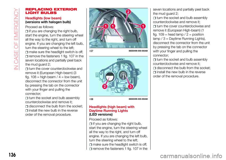
remove the fasteners 1 fig. 107 in the
seven locations and partially peel back
the mud guard 2;
turn the cover counterclockwise and
remove it (European High-beam) (3
fig.108=highbeam/4=lowbeam),
disconnect the connector from the unit
by pressing the tab on the connector
with your finger and pulling the
connector;
turn the socket and bulb assembly
counterclockwise and remove it;
disconnect the bulb from the socket;
install the new bulb in the reverse
order of the removal procedure.Headlights (high beam) with
Daytime Running Lights
(LED versions)
Proceed as follows:
if you are changing the right bulb,
start the engine, turn the steering wheel
all the way to the right, and turn off
engine. If you are changing the left bulb,
turn the steering wheel to the left;
make sure the headlight switch is off;
remove the fasteners 1 fig. 107 in theseven locations and partially peel back
the mud guard 2;
turn the socket and bulb assembly
counterclockwise and remove it;
turn the cover counterclockwise and
remove it (European High-beam) (1
fig.109=headlamp/2=position
lamp/3=DaytimeRunning Lights),
disconnect the connector from the unit
by pressing the tab on the connector
with your finger and pulling the
connector;
turn the socket and bulb assembly
counterclockwise and remove it;
disconnect the bulb from the socket;
install the new bulb in the reverse
order of the removal procedure.
10708020499-000-003AB
10808020499-000-002AB
136
IN CASE OF EMERGENCY
Page 139 of 220

Front direction indicator lights
Proceed as follows:
if you are changing the right bulb,
start the engine, turn the steering wheel
all the way to the right, and turn off
engine. If you are changing the left bulb,
turn the steering wheel to the left.
make sure the ignition is switched
off, and the headlight switch is off;
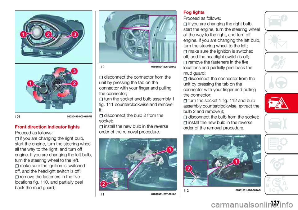
remove the fasteners in the five
locations fig. 110, and partially peel
back the mud guard;
disconnect the connector from the
unit by pressing the tab on the
connector with your finger and pulling
the connector;
turn the socket and bulb assembly 1
fig. 111 counterclockwise and remove
it;
disconnect the bulb 2 from the
socket;
install the new bulb in the reverse
order of the removal procedure.Fog lights
Proceed as follows:
if you are changing the right bulb,
start the engine, turn the steering wheel
all the way to the right, and turn off
engine. If you are changing the left bulb,
turn the steering wheel to the left;
make sure the ignition is switched
off, and the headlight switch is off;
remove the fasteners in the five
locations and partially peel back the
mud guard;
disconnect the connector from the
unit by pressing the tab on the
connector with your finger and pulling
the connector;
turn the socket 1 fig. 112 and bulb
assembly counterclockwise, extract the
bulb 2 and remove it;
disconnect the bulb from the socket;
install the new bulb in the reverse
order of the removal procedure.
10908020499-000-010AB
11007031501-206-002AB
11107031501-207-001AB11207031501-208-001AB
137
Page 140 of 220

Brake lights / Tail lights
Go to an Abarth Dealership when the
replacement of this lights is necessary.
Side direction indicator lights
Proceed as follows:
make sure the ignition is switched
off, and the headlight switch is off;
if you are changing the right bulb,
start the engine, turn the steering wheel
all the way to the right, and turn off
engine. If you are changing the left bulb,
turn the steering wheel to the left;
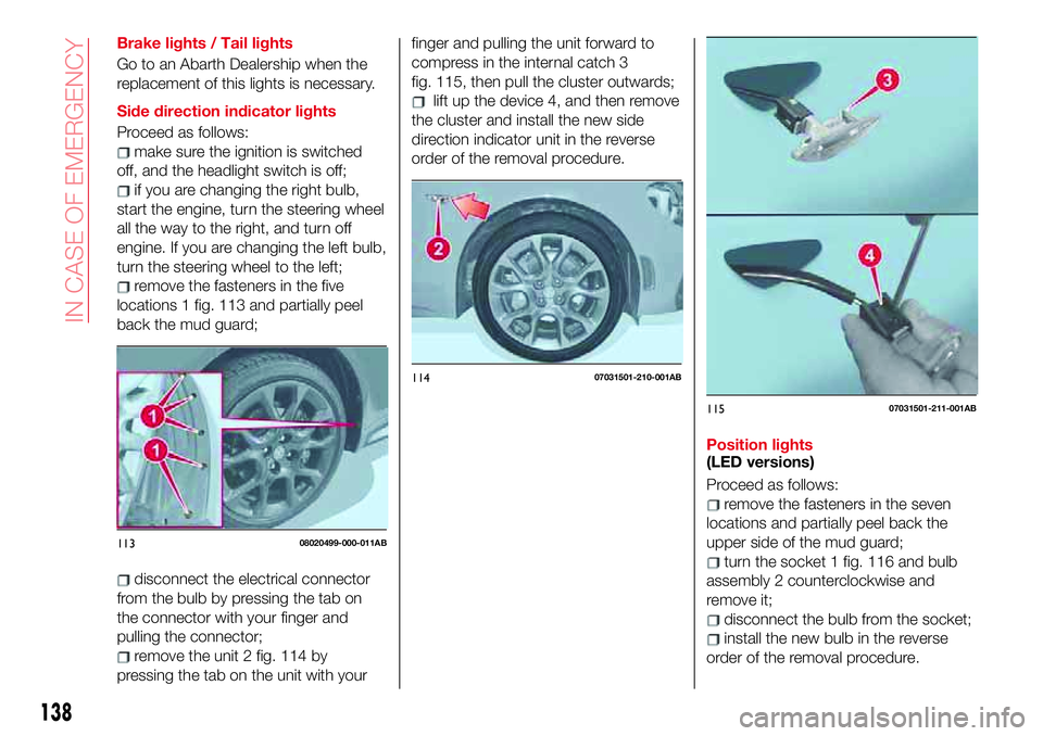
remove the fasteners in the five
locations 1 fig. 113 and partially peel
back the mud guard;
disconnect the electrical connector
from the bulb by pressing the tab on
the connector with your finger and
pulling the connector;
remove the unit 2 fig. 114 by
pressing the tab on the unit with yourfinger and pulling the unit forward to
compress in the internal catch 3
fig. 115, then pull the cluster outwards;
lift up the device 4, and then remove
the cluster and install the new side
direction indicator unit in the reverse
order of the removal procedure.
Position lights
(LED versions)
Proceed as follows:
remove the fasteners in the seven
locations and partially peel back the
upper side of the mud guard;
turn the socket 1 fig. 116 and bulb
assembly 2 counterclockwise and
remove it;
disconnect the bulb from the socket;
install the new bulb in the reverse
order of the removal procedure.
11308020499-000-011AB
11407031501-210-001AB
11507031501-211-001AB
138
IN CASE OF EMERGENCY
Page 141 of 220

Rear direction indicator lights
Proceed as follows:
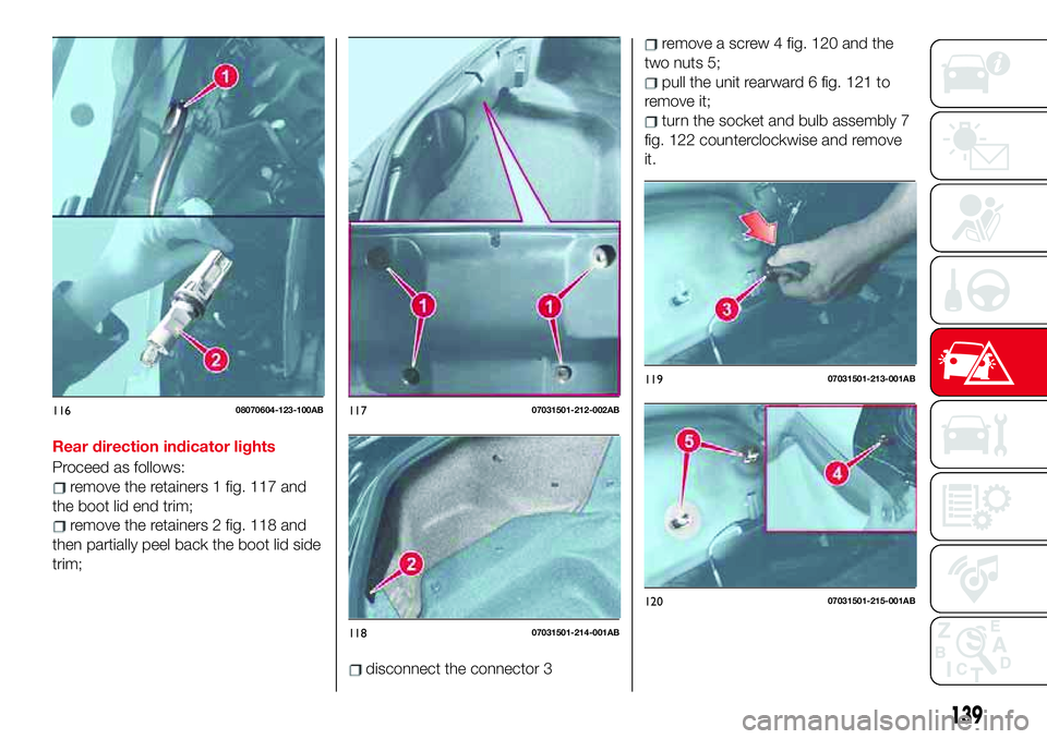
remove the retainers 1 fig. 117 and
the boot lid end trim;
remove the retainers 2 fig. 118 and
then partially peel back the boot lid side
trim;
disconnect the connector 3
remove a screw 4 fig. 120 and the
two nuts 5;
pull the unit rearward 6 fig. 121 to
remove it;
turn the socket and bulb assembly 7
fig. 122 counterclockwise and remove
it.
11608070604-123-100AB11707031501-212-002AB
11807031501-214-001AB
11907031501-213-001AB
12007031501-215-001AB
139
Page 142 of 220

Reverse light / Rear fog light
Proceed as follows:
make sure the ignition is switched
off, and the headlight switch is off;
disconnect the electrical connector
from the bulb by pressing the tab on
the connector with your finger and
pulling the connector;
turn the socket and bulb assembly
counterclockwise and remove it: 1 =reverse light/2=rearfoglight;
disconnect the bulb from the socket;
install the new bulb in the reverse
order of the removal procedure.
Number plate lights
Proceed as follows:
make sure the ignition is switched
off, and the headlight switch is off;
slide the unit 1 fig. 124 as shown in
the figure to remove it,
disconnect the electrical connector
from the unit;
install the new unit in the reverse
order of the removal procedure.
WARNING
161)Changes or repairs to the electrical
system carried out incorrectly and without
due consideration for the technical
specifications of the system may lead to
malfunctioning and generate a fire hazard.
162)Before replacing the bulb, wait for the
exhaust ducts to cool down: DANGER OF
SCALDING!
12107031501-216-001AB
12207031501-203-002AB
12308020499-000-012AB
12407031501-220-001AB
140
IN CASE OF EMERGENCY
Page 152 of 220

IMPORTANT If there is air remaining in
the tire when the valve core is removed,
the valve core could fly out. Remove
the valve core carefully.
turn the valve core 7 counter
clockwise with the valve core tool 8 and
remove the valve core fig. 134;
IMPORTANT Store the valve core in a
place where it will not get dirty.
insert the injection hose 9
fig. 135 into the valve 10;
hold the bottom of the bottle upright
11 fig. 136, squeeze the bottle with
your hands, and inject the entire
amount of tire sealant into the tire;
pull out the injection hose from the
valve fig. 137;
reinsert the valve core 12 into the
valve 13 and turn it clockwise to install.
IMPORTANT The tire sealant cannot be
reused. Purchase a new tire sealant kit
at an Abarth Dealership.
IMPORTANT Do not throw away the
empty tire sealant bottle after use.
Return the empty tire sealant bottle to
an Abarth Dealership when replacing
the tire. The empty tire sealant bottle
will need to be used to extract and
dispose of the used sealant from the
tire.
after that, install the injection hose to
the tab 14 fig. 138 of the bottle to
prevent leakage of any remaining
sealant;
adhere the speed restriction sticker
to an area where it can be viewed easily
by the driver;
pull out the air compressor hose and
the air compressor plug from the air
compressor 15 fig. 139;
13408020202-03A-005AB
13508020202-03A-006AB
13608020202-03A-008AB
13708020202-03A-007AB
150
IN CASE OF EMERGENCY