Page 237 of 356
KICKSTATER
5-44
EAS1SM9246
KICKSTATER
Removing the kick shaft
Order Part name Q’ty Remarks
Primary driven gear Refer to “CLUTCH” on page 5-35.
1 Kick idle gear 1
2 Kick shaft assembly 1
3 Spring guide 1
4 Torsion spring 1
5 Ratchet wheel 1
6 Kick gear 1
7 Kick shaft 1
For installation, reverse the removal proce-
dure.
Page 238 of 356

KICKSTATER
5-45
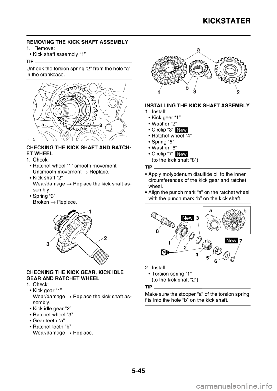
EAS1SM9247REMOVING THE KICK SHAFT ASSEMBLY
1. Remove:
• Kick shaft assembly “1”
TIP
Unhook the torsion spring “2” from the hole “a”
in the crankcase.
EAS1SM9248CHECKING THE KICK SHAFT AND RATCH-
ET WHEEL
1. Check:
• Ratchet wheel “1” smooth movement
Unsmooth movement Replace.
• Kick shaft “2”
Wear/damage Replace the kick shaft as-
sembly.
• Spring “3”
Broken Replace.
EAS1SM9249CHECKING THE KICK GEAR, KICK IDLE
GEAR AND RATCHET WHEEL
1. Check:
• Kick gear “1”
Wear/damage Replace the kick shaft as-
sembly.
• Kick idle gear “2”
• Ratchet wheel “3”
• Gear teeth “a”
• Ratchet teeth “b”
Wear/damage Replace.
EAS1SM9250INSTALLING THE KICK SHAFT ASSEMBLY
1. Install:
• Kick gear “1”
• Washer “2”
• Circlip “3”
• Ratchet wheel “4”
• Spring “5”
• Washer “6”
• Circlip “7”
(to the kick shaft “8”)
TIP
• Apply molybdenum disulfide oil to the inner
circumferences of the kick gear and ratchet
wheel.
• Align the punch mark “a” on the ratchet wheel
with the punch mark “b” on the kick shaft.
2. Install:
• Torsion spring “1”
(to the kick shaft “2”)
TIP
Make sure the stopper “a” of the torsion spring
fits into the hole “b” on the kick shaft.
31
2
a
b
3
12
New
New
Page 239 of 356
KICKSTATER
5-46
3. Install:
•Transmission
TIP
Slide the spring guide into the kick shaft, make
sure the groove “a” in the spring guide fits on
the stopper of the torsion spring.
4. Install:
• Kick shaft assembly “1”
TIP
• Before installation, apply molybdenum disul-
fide grease to the contacting surfaces of the
kick shaft ratchet wheel guide “2” and the kick
shaft stopper “a”.
• Apply the engine oil on the kick shaft.
• Slide the kick shaft assembly into the crank-
case and make sure the kick shaft stopper “a”
fits into the kick shaft ratchet wheel guide.5. Install:
• Torsion spring “1”
TIP
Turn the torsion spring clockwise and hook into
the proper hole “a” in the crankcase.
EAS1SM9251INSTALLING THE KICK IDLE GEAR
1. Install:
• Kick idle gear “1”
• Washer “2”
• Circlip “3”
TIP
• Apply the engine oil on the kick idle gear inner
circumference.
• Install the kick idle gear with its depressed
side “a” toward you.
1 2a b
New
Page 265 of 356

TRANSMISSION
5-72
2. Install:
• 2nd wheel gear (28T) “1”
• 4th wheel gear (22T) “2”
• 3rd wheel gear (26T) “3”
• 5th wheel gear (25T) “4”
• Collar “5”
• 1st wheel gear (30T) “6”
• O-rings “7”
(to the drive axle “8”)
TIP
• Before installation, apply molybdenum disul-
fide oil to the inner and end surface of the idler
gear and to the inner surface of the sliding
gear, then install.
• Apply the lithium-soap-based grease on the
O-ring.
3. Install:
• Washer “1”
• Circlip “2”
TIP
• Be sure the circlip sharp-edged corner “a” is
positioned opposite side to the washer and
gear “b”.
• Install the circlip with its ends “c” settled even-
ly on the spline crests.4. Install:
• Collar “1”
TIP
• Apply the lithium soap base grease on the oil
seal lip.
• When installing the collar into the crankcase,
pay careful attention to the crankcase oil seal
lip.
5. Install:
• Main axle “1”
• Drive axle “2”
TIP
• Install to the left crankcase simultaneously.
• Apply engine oil to the main axle and the drive
axle bearing.
New
187
2
3
4
5
6
New
M
LS
M
New
21
2
ab
cc
1
2
EE
Page 266 of 356
TRANSMISSION
5-73
6. Install:
• Shift fork 1 (L) “1”
• Shift fork 2 (C) “2”
• Shift fork 3 (R) “3”
• Shift cam “4”
(to the main axle and the drive axle)
TIP
• Apply engine oil to the shift fork grooves.
• Apply engine oil to the shift cam groove and
the bearing contact surface.
• Mesh the shift fork 1 (L) with the 4th wheel
gear “5” and 3 (R) with the 5th wheel gear “7”
on the drive axle.
• Mesh the shift fork 2 (C) with the 3rd pinion
gear “6” on the main axle.7. Install:
• Long shift fork guide bar “1”
• Short shift fork guide bar “2”
• Spring “3”
TIP
• Screw the spring into the shift fork guide bar
lightly beforehand.
• Apply the engine oil on the shift fork guide
bars.
8. Check:
• Operation of shift cam and shift fork
• Transmission operation
Unsmooth operation Repair.
3
12
6
24
5
3
7
1
E
E
E
2 13
E
Page 338 of 356

TROUBLESHOOTING
9-3
Fuel system
1. Throttle body
• Damaged or loose throttle body joint
2. Air filter
• Clogged air filter element
Chassis
1. Brake(s)
• Dragging brake
Electrical system
1. Spark plug
• Incorrect spark plug gap
• Incorrect spark plug heat range
2. Ignition system
• Faulty ECU
• Faulty coolant temperature sensor
EAS1SM9359OVERCOOLING
Cooling system
1. Coolant temperature sensor
• Faulty coolant temperature sensor
EAS1SM9360POOR BRAKING PERFORMANCE
Chassis
1. Brake(s)
• Worn brake pad
• Worn brake disc
• Air in hydraulic brake system
• Leaking brake fluid
• Defective master cylinder kit
• Faulty brake caliper kit
• Faulty brake caliper seal
• Loose union bolt
• Damaged brake hose
• Oil or grease on the brake disc
• Oil or grease on the brake pad
• Incorrect brake fluid level
EAS1SM9361FRONT FORK OIL LEAKING
Chassis
1. Front fork
• Bent, damaged, or rusty inner tube
• Cracked or damaged outer tube
• Improperly installed oil seal
• Damaged oil seal lip
• Incorrect oil level (high)
• Loose damper rod assembly bolt
• Damaged damper rod assembly bolt copper
washer
• Cracked or damaged cap bolt O-ring
EAS1SM9362FAULTY FRONT FORK LEGS
Chassis
1. Front fork
• Bent or damaged inner tube
• Bent or damaged outer tube
• Broken fork spring
• Bent or damaged damper rod
• Incorrect oil viscosity
• Incorrect oil level
EAS1SM9363UNSTABLE HANDLING
Chassis
1. Handlebar
• Bent or improperly installed handlebar
2. Steering head components
• Improperly installed upper bracket
• Improperly installed lower bracket
(improperly tightened ring nut)
• Bent steering stem
• Damaged ball bearing or bearing race
3. Front fork leg (s)
• Uneven oil levels (both front fork legs)
• Unevenly tensioned fork spring (both front
fork legs)
• Broken fork spring
• Bent or damaged inner tube
• Bent or damaged outer tube
4. Swingarm
• Worn bearing or bushing
• Bent or damaged swingarm
5. Rear shock absorber assembly (-ies)
• Faulty rear shock absorber spring
• Leaking oil or gas
6. Tire (s)
• Uneven tire pressures (front and rear)
• Incorrect tire pressure
• Uneven tire wear
7. Wheel (s)
• Incorrect wheel balance
• Broken or loose spoke
• Damaged wheel bearing
• Bent or loose wheel axle
• Excessive wheel runout
8. Frame
• Bent frame
• Damaged steering head pipe
• Improperly installed bearing race
Page 343 of 356

10
TUNING
CHASSIS........................................................................................................ 10-1
SELECTION OF THE SECONDARY REDUCTION
RATIO (SPROCKET) .............................................................................. 10-1
DRIVE AND REAR WHEEL SPROCKETS SETTING PARTS ................ 10-1
TIRE PRESSURE..................................................................................... 10-2
FRONT FORK SETTING.......................................................................... 10-2
CHANGE IN AMOUNT AND CHARACTERISTICS OF FORK OIL.......... 10-2
SETTING OF SPRING AFTER REPLACEMENT .................................... 10-3
FRONT FORK SETTING PARTS............................................................. 10-3
REAR SUSPENSION SETTING .............................................................. 10-3
CHOOSING SET LENGTH ...................................................................... 10-3
SETTING OF SPRING AFTER REPLACEMENT .................................... 10-4
REAR SHOCK ABSORBER SETTING PARTS ....................................... 10-5
SUSPENSION SETTING (FRONT FORK)............................................... 10-6
SUSPENSION SETTING (REAR SHOCK ABSORBER) ......................... 10-7
Page 344 of 356

CHASSIS
10-1
EAS1SM9366
CHASSIS
EAS1SM9367SELECTION OF THE SECONDARY REDUC-
TION RATIO (SPROCKET)
reduction ratio>
• It is generally said that the secondary gear ra-
tio should be reduced for a longer straight por-
tion of a speed course and should be
increased for a course with many corners. Ac-
tually, however, as the speed depends on the
ground condition of the day of the race, be
sure to run through the circuit to set the ma-
chine suitable for the entire course.
• In actuality, it is very difficult to achieve set-
tings suitable for the entire course and some
settings may be sacrificed. Thus, the settings
should be matched to the portion of the
course that has the greatest effect on the race
result. In such a case, run through the entire
course while making notes of lap times to find
the best balance; then, determine the second-
ary reduction ratio.
• If a course has a long straight portion where a
machine can run at maximum speed, the ma-
chine is generally set such that it can develop
its maximum revolutions toward the end of the
straight line, with care taken to avoid the en-
gine over-revving.
TIP
Riding technique varies from rider to rider and
the performance of a machine also vary from
machine to machine. Therefore, do not imitate
other rider’s settings from the beginning but
choose your own setting according to the level
of your riding technique.
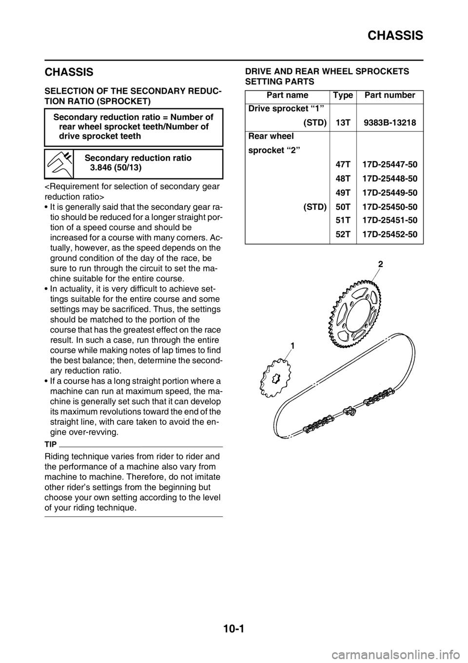
EAS1SM9368DRIVE AND REAR WHEEL SPROCKETS
SETTING PARTS
Secondary reduction ratio = Number of
rear wheel sprocket teeth/Number of
drive sprocket teeth
Secondary reduction ratio
3.846 (50/13)
Part name Type Part number
Drive sprocket “1”
(STD) 13T 9383B-13218
Rear wheel
sprocket “2”
47T 17D-25447-50
48T 17D-25448-50
49T 17D-25449-50
(STD) 50T 17D-25450-50
51T 17D-25451-50
52T 17D-25452-50