2016 YAMAHA YZ250F wheel
[x] Cancel search: wheelPage 139 of 356
FRONT BRAKE
4-15
EAS1SM9134INTRODUCTIONEWA
WARNING
If you need to disassemble the disc brake
components, observe the following precau-
tions.
• Never disassemble the brake components
unless absolutely necessary.
• If there is any problem with connections
on the hydraulic brake system, perform
the following jobs.
Disassemble the brake system, drain the
brake fluid, and clean it. After that, add a
suitable amount of brake fluid. Then, bleed
it after reassembly.
• Use only brake fluid for washing brake
components.
• Use new brake fluid for cleaning the brake
components.
• Immediately wipe off the spilled brake fluid
to avoid damage to painted surfaces or
plastic parts.
• Handle brake fluid with special care not to
let it enter your eyes so that you may not
lost your eyesight.
• FIRST AID FOR BRAKE FLUID ENTERING
THE EYES:
• Flush with water for 15 minutes and get
immediate medical attention.
EAS1SM9135CHECKING THE FRONT BRAKE DISC
1. Remove:
• Front wheel
Refer to “FRONT WHEEL” on page 4-3.
2. Check:
• Front brake disc
Damage/galling Replace.
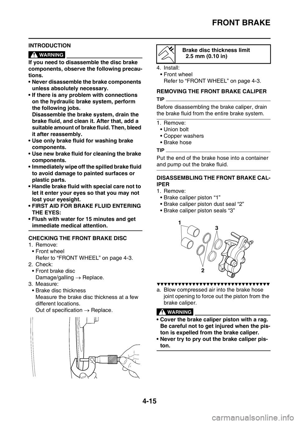
3. Measure:
• Brake disc thickness
Measure the brake disc thickness at a few
different locations.
Out of specification Replace.4. Install:
• Front wheel
Refer to “FRONT WHEEL” on page 4-3.
EAS1SM9136REMOVING THE FRONT BRAKE CALIPER
TIP
Before disassembling the brake caliper, drain
the brake fluid from the entire brake system.
1. Remove:
• Union bolt
• Copper washers
• Brake hose
TIP
Put the end of the brake hose into a container
and pump out the brake fluid.
EAS1SM9137DISASSEMBLING THE FRONT BRAKE CAL-
IPER
1. Remove:
• Brake caliper piston “1”
• Brake caliper piston dust seal “2”
• Brake caliper piston seals “3”
▼▼▼▼▼▼▼▼▼▼▼▼▼▼▼▼▼▼▼▼▼▼▼▼▼▼▼▼▼▼▼▼
a. Blow compressed air into the brake hose
joint opening to force out the piston from the
brake caliper.
EWA
WARNING
• Cover the brake caliper piston with a rag.
Be careful not to get injured when the pis-
ton is expelled from the brake caliper.
• Never try to pry out the brake caliper pis-
ton.
Brake disc thickness limit
2.5 mm (0.10 in)
3
2
1
Page 149 of 356

REAR BRAKE
4-25
EAS1SM9147INTRODUCTIONEWA
WARNING
If you need to disassemble the disc brake
components, observe the following precau-
tions.
• Never disassemble the brake components
unless absolutely necessary.
• If there is any problem with connections
on the hydraulic brake system, perform
the following jobs.
Disassemble the brake system, drain the
brake fluid, and clean it. After that, add a
suitable amount of brake fluid. Then, bleed
it after reassembly.
• Use only brake fluid for washing internal
brake components.
• Use new brake fluid for cleaning the brake
components.
• Immediately wipe off the spilled brake fluid
to avoid damage to painted surfaces or
plastic parts.
• Handle brake fluid with special care not to
let it enter your eyes so that you may not
lost your eyesight.
• FIRST AID FOR BRAKE FLUID ENTERING
THE EYES:
• Flush with water for 15 minutes and get
immediate medical attention.
EAS1SM9148CHECKING THE REAR BRAKE DISC
1. Remove:
• Rear wheel
Refer to “REAR WHEEL” on page 4-7.
2. Check:
• Brake disc
Damage/galling Replace.
3. Measure:
• Brake disc thickness
Measure the brake disc thickness at a few
different locations.
Out of specification Replace.
Refer to “CHECKING THE FRONT BRAKE
DISC” on page 4-15.
4. Measure:
• Brake disc deflection
Out of specification Correct the brake disc
deflection or replace the brake disc.5. Adjust:
• Brake disc deflection
▼▼▼▼▼▼▼▼▼▼▼▼▼▼▼▼▼▼▼▼▼▼▼▼▼▼▼▼▼▼▼▼
a. Remove the brake disc.
b. Turn the mounted position of the brake disc
by one bolt hole.
c. Install the brake disc.
TIP
Tighten the brake disc bolts in stages and in a
crisscross pattern.
d. Measure the brake disc deflection.
e. If out of specification, repeat the adjustment
steps until the brake disc deflection is within
specification.
f. If the brake disc deflection cannot be
brought within specification, replace the
brake disc.
▲▲▲▲▲▲▲▲▲▲▲▲▲▲▲▲▲▲▲▲▲▲▲▲▲▲▲▲▲▲▲▲
6. Install:
• Rear wheel
Refer to “REAR WHEEL” on page 4-7. Brake disc thickness limit
3.5 mm (0.14 in)
Brake disc runout limit (as mea-
sured on wheel)
0.15 mm (0.0059 in)
Brake disc bolt
14 Nm (1.4 m·kgf, 10 ft·lbf)
LOCTITE®
T R..
Page 151 of 356
REAR BRAKE
4-27
EAS1SM9153INSTALLING THE BRAKE CALIPER PISTON
1. Clean:
• Brake caliper
• Brake caliper piston seal
• Brake caliper piston dust seal
• Brake caliper piston
Use brake fluid for cleaning.
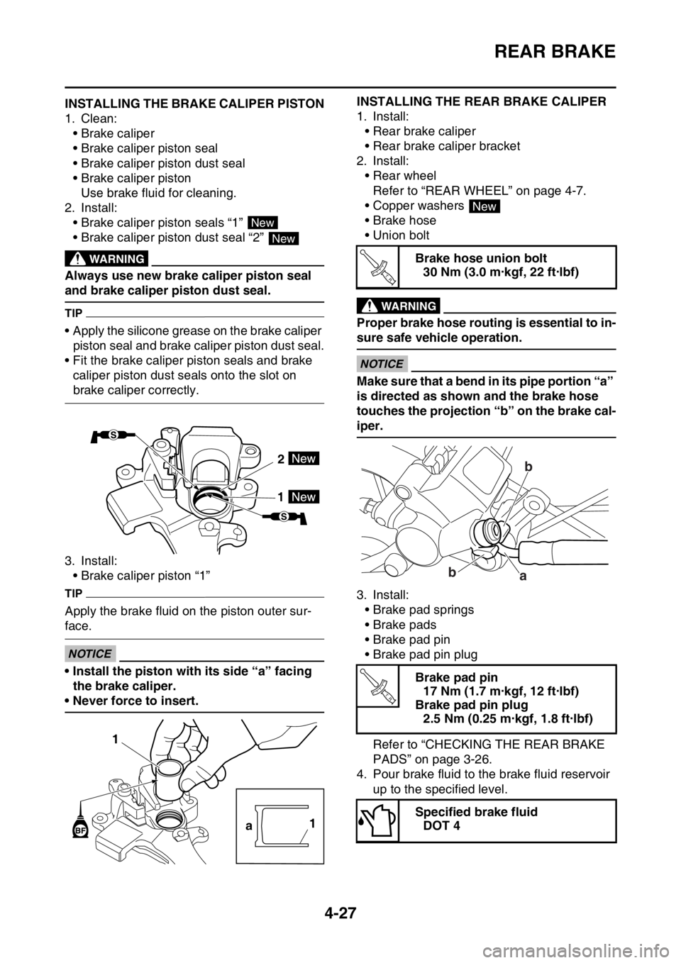
2. Install:
• Brake caliper piston seals “1”
• Brake caliper piston dust seal “2”
EWA
WARNING
Always use new brake caliper piston seal
and brake caliper piston dust seal.
TIP
• Apply the silicone grease on the brake caliper
piston seal and brake caliper piston dust seal.
• Fit the brake caliper piston seals and brake
caliper piston dust seals onto the slot on
brake caliper correctly.
3. Install:
• Brake caliper piston “1”
TIP
Apply the brake fluid on the piston outer sur-
face.
ECA
NOTICE
• Install the piston with its side “a” facing
the brake caliper.
• Never force to insert.
EAS1SM9154
INSTALLING THE REAR BRAKE CALIPER
1. Install:
• Rear brake caliper
• Rear brake caliper bracket
2. Install:
• Rear wheel
Refer to “REAR WHEEL” on page 4-7.
• Copper washers
• Brake hose
• Union bolt
EWA
WARNING
Proper brake hose routing is essential to in-
sure safe vehicle operation.
ECA
NOTICE
Make sure that a bend in its pipe portion “a”
is directed as shown and the brake hose
touches the projection “b” on the brake cal-
iper.
3. Install:
• Brake pad springs
• Brake pads
• Brake pad pin
• Brake pad pin plug
Refer to “CHECKING THE REAR BRAKE
PADS” on page 3-26.
4. Pour brake fluid to the brake fluid reservoir
up to the specified level.
New
New
2
1
1
a1
Brake hose union bolt
30 Nm (3.0 m·kgf, 22 ft·lbf)
Brake pad pin
17 Nm (1.7 m·kgf, 12 ft·lbf)
Brake pad pin plug
2.5 Nm (0.25 m·kgf, 1.8 ft·lbf)
Specified brake fluid
DOT 4
New
T R..
b
b
a
T R..
Page 161 of 356
FRONT FORK
4-37
EAS1SM9163
FRONT FORK
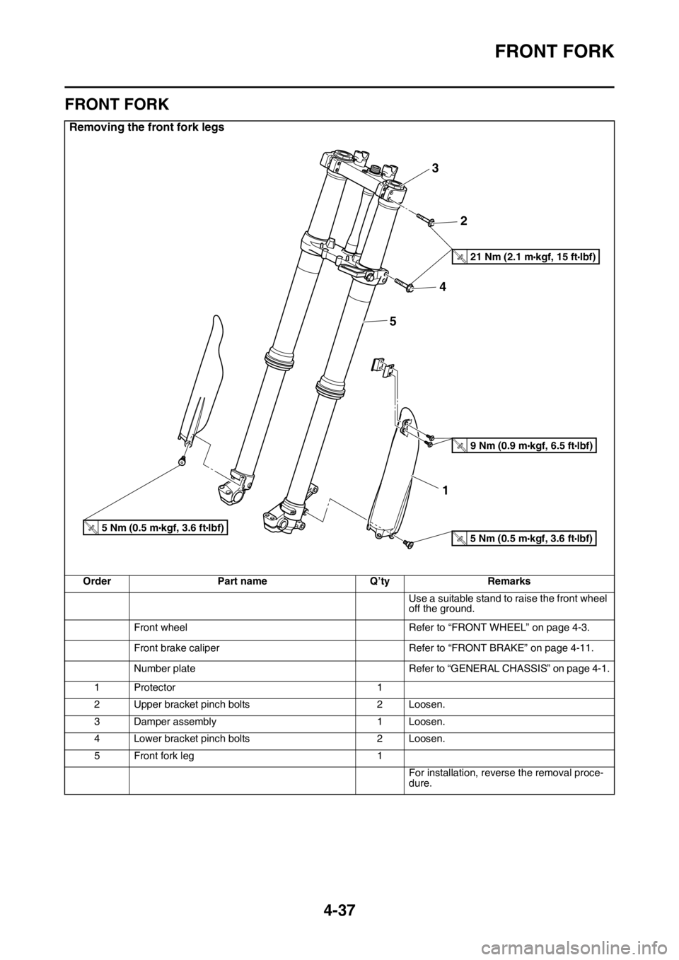
Removing the front fork legs
Order Part name Q’ty Remarks
Use a suitable stand to raise the front wheel
off the ground.
Front wheel Refer to “FRONT WHEEL” on page 4-3.
Front brake caliper Refer to “FRONT BRAKE” on page 4-11.
Number plate Refer to “GENERAL CHASSIS” on page 4-1.
1 Protector 1
2 Upper bracket pinch bolts 2 Loosen.
3 Damper assembly 1 Loosen.
4 Lower bracket pinch bolts 2 Loosen.
5 Front fork leg 1
For installation, reverse the removal proce-
dure.
3
2
4
5
1
T.R.21 Nm (2.1 mlbf) kgf, 15 ft
T.R.9 Nm (0.9 mlbf) kgf, 6.5 ft
T.R.5 Nm (0.5 mlbf) kgf, 3.6 ftT.R.5 Nm (0.5 mlbf) kgf, 3.6 ft
Page 163 of 356
FRONT FORK
4-39
EAS1SM9164REMOVING THE FRONT FORK LEGS
1. Use a suitable stand to raise the front wheel
off the ground.
EWAWARNING
Securely support the vehicle so that there is
no danger of it falling over.
TIP
Record the adjusting screw setting position be-
fore loosening the adjuster and the base valve.
2. Loosen:
• Upper bracket pinch bolts
• Damper assembly
• Lower bracket pinch bolts
EWAWARNING
Before loosening the upper and lower
bracket pinch bolts, support the front fork
leg.
TIP
Before removing the front fork leg from the ve-
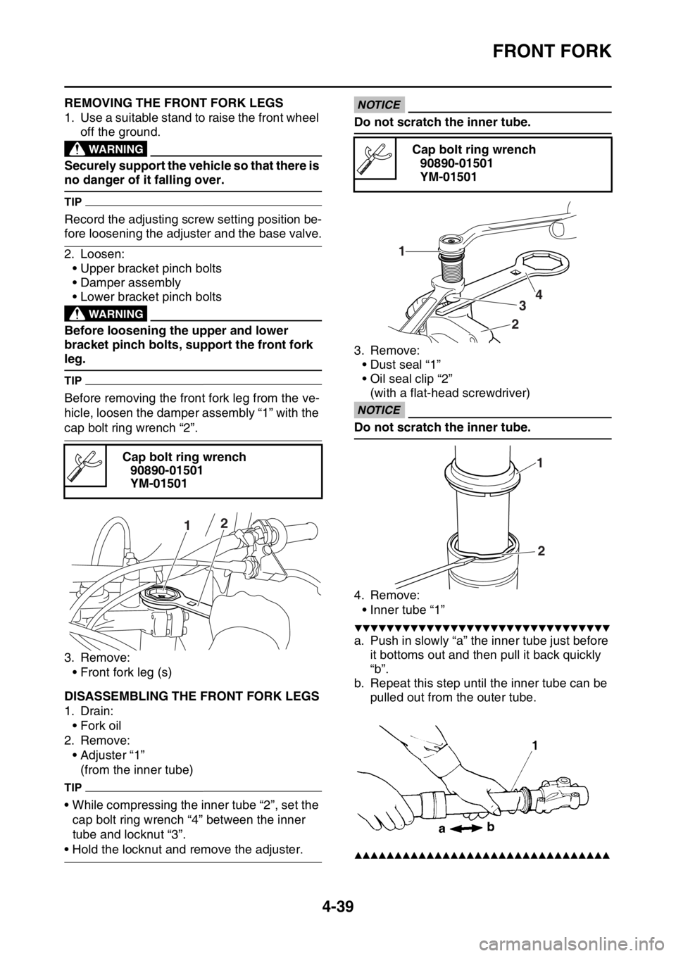
hicle, loosen the damper assembly “1” with the
cap bolt ring wrench “2”.
3. Remove:
• Front fork leg (s)
EAS1SM9165DISASSEMBLING THE FRONT FORK LEGS
1. Drain:
• Fork oil
2. Remove:
• Adjuster “1”
(from the inner tube)
TIP
• While compressing the inner tube “2”, set the
cap bolt ring wrench “4” between the inner
tube and locknut “3”.
• Hold the locknut and remove the adjuster.
ECA
NOTICE
Do not scratch the inner tube.
3. Remove:
• Dust seal “1”
• Oil seal clip “2”
(with a flat-head screwdriver)
ECANOTICE
Do not scratch the inner tube.
4. Remove:
• Inner tube “1”
▼▼▼▼▼▼▼▼▼▼▼▼▼▼▼▼▼▼▼▼▼▼▼▼▼▼▼▼▼▼▼▼
a. Push in slowly “a” the inner tube just before
it bottoms out and then pull it back quickly
“b”.
b. Repeat this step until the inner tube can be
pulled out from the outer tube.
▲▲▲▲▲▲▲▲▲▲▲▲▲▲▲▲▲▲▲▲▲▲▲▲▲▲▲▲▲▲▲▲
Cap bolt ring wrench
90890-01501
YM-01501
12
Cap bolt ring wrench
90890-01501
YM-01501
1
234
1
2
Page 173 of 356
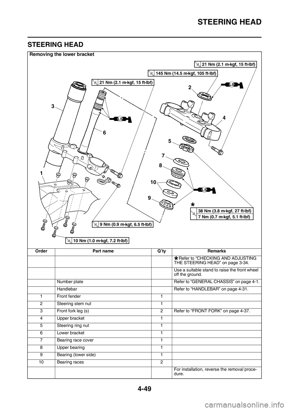
STEERING HEAD
4-49
EAS1SM9169
STEERING HEAD
Removing the lower bracket
Order Part name Q’ty Remarks
Refer to “CHECKING AND ADJUSTING
THE STEERING HEAD” on page 3-34.
Use a suitable stand to raise the front wheel
off the ground.
Number plate Refer to “GENERAL CHASSIS” on page 4-1.
Handlebar Refer to “HANDLEBAR” on page 4-31.
1 Front fender 1
2 Steering stem nut 1
3 Front fork leg (s) 2 Refer to “FRONT FORK” on page 4-37.
4 Upper bracket 1
5 Steering ring nut 1
6 Lower bracket 1
7 Bearing race cover 1
8 Upper bearing 1
9 Bearing (lower side) 1
10 Bearing races 2
For installation, reverse the removal proce-
dure.
2
4
5
7
3
1
6
8
9
10
LS
T
.R.
LS
LS
T
.R.21 Nm (2.1 mlbf) kgf, 15 ft
T
.R.9 Nm (0.9 mlbf) kgf, 6.5 ft
T
.R.21 Nm (2.1 mlbf) kgf, 15 ft
T
.R.10 Nm (1.0 mlbf) kgf, 7.2 ft
T
.R.145 Nm (14.5 mlbf) kgf, 105 ft
38 Nm (3.8 m
lbf) kgf, 27 ft
7 Nm (0.7 m
lbf) kgf, 5.1 ft
*
*
Page 174 of 356
STEERING HEAD
4-50
EAS1SM9170REMOVING THE LOWER BRACKET
1. Use a suitable stand to raise the front wheel
off the ground.
EWA
WARNING
Securely support the vehicle so that there is
no danger of it falling over.
2. Remove:
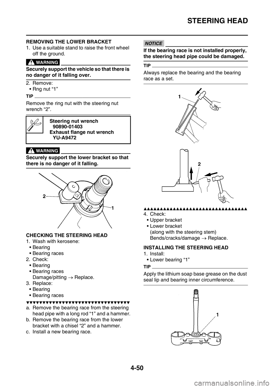
• Rng nut “1”
TIP
Remove the ring nut with the steering nut
wrench “2”.
EWA
WARNING
Securely support the lower bracket so that
there is no danger of it falling.
EAS1SM9171CHECKING THE STEERING HEAD
1. Wash with kerosene:
• Bearing
• Bearing races
2. Check:
• Bearing
• Bearing races
Damage/pitting Replace.
3. Replace:
• Bearing
• Bearing races
▼▼▼▼▼▼▼▼▼▼▼▼▼▼▼▼▼▼▼▼▼▼▼▼▼▼▼▼▼▼▼▼
a. Remove the bearing race from the steering
head pipe with a long rod “1” and a hammer.
b. Remove the bearing race from the lower
bracket with a chisel “2” and a hammer.
c. Install a new bearing race.
ECA
NOTICE
If the bearing race is not installed properly,
the steering head pipe could be damaged.
TIP
Always replace the bearing and the bearing
race as a set.
▲▲▲▲▲▲▲▲▲▲▲▲▲▲▲▲▲▲▲▲▲▲▲▲▲▲▲▲▲▲▲▲
4. Check:
• Upper bracket
• Lower bracket
(along with the steering stem)
Bends/cracks/damage Replace.
EAS1SM9172INSTALLING THE STEERING HEAD
1. Install:
• Lower bearing “1”
TIP
Apply the lithium soap base grease on the dust
seal lip and bearing inner circumference. Steering nut wrench
90890-01403
Exhaust flange nut wrench
YU-A9472
Page 180 of 356

REAR SHOCK ABSORBER ASSEMBLY
4-56
EAS1SM9174HANDLING THE REAR SHOCK ABSORBEREWAWARNING
This rear shock absorber contains highly
compressed nitrogen gas. Before handling
the rear shock absorber, read and make
sure that you understand the following in-
formation. The manufacturer cannot be held
responsible for property damage or person-
al injury that may result from improper han-
dling of the rear shock absorber.
• Do not tamper or attempt to open the rear
shock absorber.
• Do not subject the rear shock absorber to
an open flame or any other source of high
heat. High heat can cause an explosion
due to excessive gas pressure.
• Do not deform or damage the rear shock
absorber in any way. Rear shock absorber
damage will result in poor damping perfor-
mance.
TIP
A break-in is required up to about 50 km of run-
ning.
EAS1SM9175DISPOSING OF A REAR SHOCK ABSORB-
ER
Before disposing the rear shock absorber, be
sure to extract the nitrogen gas from valve “1”.
EWA
WARNING
• Wear protective glasses to prevent your
eyes from damage due to possible gas or
metal chips scattered.
• To dispose of a damaged or a worn-out
rear shock absorber, take the unit to your
Yamaha dealer for this disposal proce-
dure.
EAS1SM9176REMOVING THE REAR SHOCK ABSORBER
ASSEMBLY
1. Use a suitable stand to raise the rear wheel
off the ground.
EWA
WARNING
Securely support the vehicle so that there is
no danger of it falling over.
2. Remove:
• Rear shock absorber assembly lower bolt
“1”
TIP
While removing the rear shock absorber as-
sembly lower bolt, hold the swingarm so that it
does not drop down.
3. Remove:
• Rear shock absorber assembly upper bolt
• Rear shock absorber assembly
EAS1SM9177REMOVING THE BEARING
1. Remove:
• Stopper ring (upper bearing) “1”
TIP
Press in the bearing while pressing its outer
race and remove the stopper ring.
1
1