Page 65 of 106

Periodic maintenance and adjustment6-12
1
2
3
4
567
8
9
10
11
12
EAU20071
CoolantThe coolant level should be checked
before each ride. In addition, the cool-
ant must be changed at the intervals
specified in the periodic maintenance
and lubrication chart.
EAU20095
To check the coolant level 1. Place the vehicle on a level sur- face and hold it in an upright posi-
tion.TIP
The coolant level must be checked
on a cold engine since the level
varies with engine temperature.
Make sure that the vehicle is posi-
tioned straight up when checking
the coolant level. A slight tilt to theside can result in a false reading.
2. Check the coolant level in the cool- ant reservoir.
TIPThe coolant should be between theminimum and maximum level marks. 3. If the coolant is at or below the
minimum level mark, remove the
reservoir cap. WARNING! Re-
move only the coolant reservoir
cap. Never attempt to remove
the radiator cap when the en-
gine is hot.
[EWA15162]
4. Add coolant to the maximum level mark, and then install the reservoir
cap. NOTICE: If coolant is not
available, use distilled water or
soft tap water instead. Do not
use hard water or salt water
since it is harmful to the engine.
If water has been used instead
of coolant, replace it with cool-
ant as soon as possible, other-
wise the cooling system will not
be protected against frost and
corrosion. If water has been
added to the coolant, have a
Yamaha dealer check the anti-
freeze content of the coolant as
soon as possible, otherwise the
1. Coolant reservoir
2. Maximum level mark
3. Minimum level mark
21
3
1. Coolant reservoir cap
1
B90-9-E0_1.book 12 ページ 2015年12月15日 火曜日 午後8時5分
Page 66 of 106
![YAMAHA XSR 900 2016 Owners Manual Periodic maintenance and adjustment
6-13
1
2
3
4
56
7
8
9
10
11
12 effectiveness of the coolant will
be reduced.
[ECA10473]
EAU57963
To change the coolant1. Place the vehicle on a level sur- face and](/manual-img/51/53095/w960_53095-65.png "YAMAHA XSR 900 2016 Owners Manual Periodic maintenance and adjustment
6-13
1
2
3
4
56
7
8
9
10
11
12 effectiveness of the coolant will
be reduced.
[ECA10473]
EAU57963
To change the coolant1. Place the vehicle on a level sur- face and")
Periodic maintenance and adjustment
6-13
1
2
3
4
56
7
8
9
10
11
12 effectiveness of the coolant will
be reduced.
[ECA10473]
EAU57963
To change the coolant1. Place the vehicle on a level sur- face and let the engine cool if nec-
essary.
2. Place a container under the engine to collect the used coolant.
3. Remove the radiator cap retaining bolt, radiator cap retainer and radi-
ator cap. WARNING! Never at-
tempt to remove the radiator
cap when the engine is
hot.
[EWA10382]
4. Remove the coolant reservoir cov- er and coolant reservoir by remov-
ing the bolts and collars. 5. Remove the coolant reservoir cap.
6. Drain the coolant from the coolant
reservoir by turning it upside down.
Coolant reservoir capacity (up to the
maximum level mark):0.25 L (0.26 US qt, 0.22 Imp.qt)
1. Radiator cap
2. Radiator cap retaining bolt
3. Radiator cap retainer
2
1
3
1. Bolt
2. Coolant reservoir cover
3. Coolant reservoir
4. Collar
1. Coolant reservoir cap
1
1
2
4
3
4
1
B90-9-E0_1.book 13 ページ 2015年12月15日 火曜日 午後8時5分
Page 67 of 106

Periodic maintenance and adjustment6-14
1
2
3
4
567
8
9
10
11
12
7. Install the coolant reservoir and its
cover by placing them in the origi-
nal position, and then installing the
collars and bolts.
8. Remove the coolant drain bolt and its gasket to drain the coolant from
the cooling system.
9. After the coolant is completely drained, thoroughly flush the cool-
ing system with clean tap water.
10. Install the coolant drain bolt and its new gasket, and then tighten the
bolt to the specified torque. 11. Pour the specified amount of the
recommended coolant into the ra-
diator and reservoir.
12. Install the coolant reservoir cap.
13. Install the radiator cap.
14. Start the engine, let it idle for sev- eral minutes, and then turn it off.
15. Remove the radiator cap to check the coolant level in the radiator. If
necessary, add sufficient coolant
until it reaches the top of the radia-
tor, and then install the radiator
cap, radiator cap retainer and radi-
ator cap retaining bolt.
16. Check the coolant level in the res- ervoir. If necessary, remove the
coolant reservoir cap, add coolant to the maximum level mark, and
then install the cap.
17. Start the engine, and then check the vehicle for coolant leakage. If
coolant is leaking, have a Yamaha
dealer check the cooling system.
1. Coolant drain bolt
2. GasketTightening torque:Coolant drain bolt:
10 Nm (1.0 m·kgf, 7.2 ft·lbf)1
2
Antifreeze/water mixture ratio:1:1
Recommended antifreeze:
High-quality ethylene glycol anti-
freeze containing co rrosion inhibitors
for aluminum engines
Coolant quantity: Radiator (including all routes):1.93 L (2.04 US qt, 1.70 Imp.qt)
Coolant reservoir (up to the maxi-
mum level mark): 0.25 L (0.26 US qt, 0.22 Imp.qt)
B90-9-E0_1.book 14 ページ 2015年12月15日 火曜日 午後8時5分
Page 68 of 106
Periodic maintenance and adjustment
6-15
1
2
3
4
56
7
8
9
10
11
12
EAU36765
Air filter elementThe air filter element must be replaced
at the intervals specified in the periodic
maintenance and lubrication chart.
Have a Yamaha dealer replace the air
filter element.
EAU44735
Checking the engine idling
speedCheck the engine idling speed and, if
necessary, have it corrected by a
Yamaha dealer.
EAU21386
Checking the throttle grip free
playMeasure the throttle grip free play as
shown.
Periodically check the throttle grip free
play and, if necessary, have a Yamaha
dealer adjust it.
Engine idling speed: 1100–1300 r/min
1. Throttle grip free playThrottle grip free play:3.0–5.0 mm (0.12–0.20 in)
1
B90-9-E0_1.book 15 ページ 2015年12月15日 火曜日 午後8時5分
Page 69 of 106

Periodic maintenance and adjustment6-16
1
2
3
4
567
8
9
10
11
12
EAU21402
Valve clearanceThe valve clearance changes with use,
resulting in improper air-fuel mixture
and/or engine noise. To prevent this
from occurring, the valve clearance
must be adjusted by a Yamaha dealer
at the intervals specified in the periodic
maintenance and lubrication chart.
EAU64410
TiresTires are the only contact between the
vehicle and the road. Safety in all con-
ditions of riding depends on a relatively
small area of road contact. Therefore, it
is essential to maintain the tires in good
condition at all times and replace them
at the appropriate time with the speci-
fied tires.
Tire air pressure
The tire air pressure should be checked
and, if necessary, adjusted before each
ride.
WARNING
EWA10504
Operation of this vehicle with im-
proper tire pressure may cause se-
vere injury or death from loss of
control.
The tire air pressure must be
checked and adjusted on cold
tires (i.e., when the temperature
of the tires equals the ambient
temperature).
The tire air pressure must be ad-
justed in accordance with the
riding speed and with the total weight of rider, passenger, car-
go, and accessories approved
for this model.WARNING
EWA10512
Never overload your vehicle. Opera-
tion of an overloaded vehicle couldcause an accident.
Tire air pressure (measured on cold
tires):
1 person:Front: 250 kPa (2.50 kgf/cm
2, 36 psi)
Rear: 290 kPa (2.90 kgf/cm2, 42 psi)
2 persons:
Front: 250 kPa (2.50 kgf/cm2, 36 psi)
Rear:
290 kPa (2.90 kgf/cm2, 42 psi)
Maximum load*: 170 kg (375 lb)
* Total weight of rider, passenger, car- go and accessories
B90-9-E0_1.book 16 ページ 2015年12月15日 火曜日 午後8時5分
Page 70 of 106

Periodic maintenance and adjustment
6-17
1
2
3
4
56
7
8
9
10
11
12 Tire inspection
The tires must be checked before each
ride. If the center tread depth reaches
the specified limit, if the tire has a nail or
glass fragments in it, or if the sidewall is
cracked, have a Yamaha dealer re-
place the tire immediately.
TIPThe tire tread depth limits may differ
from country to country. Always complywith the local regulations.
WARNING
EWA10472
Have a Yamaha dealer replace
excessively worn tires. Besides
being illegal, operating the vehi-
cle with excessively worn tires
decreases riding stability and
can lead to loss of control.
The replacement of all wheel
and brake-related parts, includ-
ing the tires, should be left to a
Yamaha dealer, who has the
necessary professional knowl-
edge and experience to do so.
Ride at moderate speeds after
changing a tire since the tire
surface must first be “broken
in” for it to develop its optimalcharacteristics.
Tire information
This model is equipped with tubeless
tires and tire air valves.
Tires age, even if they have not been
used or have only been used occasion-
ally. Cracking of the tread and sidewall
rubber, sometimes accompanied by
carcass deformation, is an evidence of
ageing. Old and aged tires shall be
checked by tire specialists to ascertain
their suitability for further use.
WARNING
EWA10902
The front and rear tires should
be of the same make and de-
1. Tire sidewall
2. Tire tread depthMinimum tire tread depth (front and
rear):
1.6 mm (0.06 in)
1. Tire air valve
2. Tire air valve core
3. Tire air valve cap with seal
B90-9-E0_1.book 17 ページ 2015年12月15日 火曜日 午後8時5分
Page 71 of 106

Periodic maintenance and adjustment6-18
1
2
3
4
567
8
9
10
11
12
sign, otherwise the handling
characteristics of the motorcy-
cle may be different, which
could lead to an accident.
Always make sure that the valve
caps are securely installed to
prevent air pressure leakage.
Use only the tire valves and
valve cores listed below toavoid tire deflation during a ride.
After extensive tests, only the tires list-
ed below have been approved for this
model by Yamaha.
WARNING
EWA10601
This motorcycle is fitted with su-
per-high-speed tires. Note the fol-
lowing points in order to make the
most efficient use of these tires.
Use only the specified replace-
ment tires. Other tires may run
the danger of bursting at super
high speeds.
Brand-new tires can have a rela-
tively poor grip on certain road
surfaces until they have been
“broken in”. Therefore, it is ad-
visable before doing any
high-speed riding to ride con-
servatively for approximately
100 km (60 mi) after installing a
new tire.
The tires must be warmed up
before a high-speed run.
Always adjust the tire air pres-
sure according to the operatingconditions.
EAU21963
Cast wheelsTo maximize the performance, durabil-
ity, and safe operation of your vehicle,
note the following points regarding the
specified wheels.
The wheel rims should be checked
for cracks, bends, warpage or oth-
er damage before each ride. If any
damage is found, have a Yamaha
dealer replace the wheel. Do not
attempt even the smallest repair to
the wheel. A deformed or cracked
wheel must be replaced.
The wheel should be balanced
whenever either the tire or wheel
has been changed or replaced. An
unbalanced wheel can result in
poor performance, adverse han-
dling characteristics, and a short-
ened tire life.
Front tire: Size:
120/70 ZR17M/C (58W)
Manufacturer/model: BRIDGESTONE/S20F M
Rear tire: Size: 180/55 ZR17M/C (73W)
Manufacturer/model: BRIDGESTONE/S20R M
FRONT and REAR:
Tire air valve: TR412
Valve core:
#9100 (original)
B90-9-E0_1.book 18 ページ 2015年12月15日 火曜日 午後8時5分
Page 72 of 106

Periodic maintenance and adjustment
6-19
1
2
3
4
56
7
8
9
10
11
12
EAU22083
Adjusting the cl utch lever free
playMeasure the clutch lever free play as
shown.
Periodically check the clutch lever free
play and, if necessary, adjust it as fol-
lows.
To increase the clutch lever free play,
turn the clutch lever free play adjusting
bolt in direction (a). To decrease the
clutch lever free play, turn the adjusting
bolt in direction (b).
TIPIf the specified free play cannot be ob-
tained as described above or if the
clutch does not operate correctly, have
a Yamaha dealer check the internalclutch mechanism.
EAU37914
Checking the brake lever free
playThere should be no free play at the
brake lever end. If there is free play,
have a Yamaha dealer inspect the
brake system.
WARNING
EWA14212
A soft or spongy feeling in the brake
lever can indicate the presence of air
in the hydraulic system. If there is air
in the hydraulic system, have a
Yamaha dealer bleed the system be-
fore operating the vehicle. Air in the
hydraulic system will diminish the
braking performance, which may re-
1. Clutch lever free play adjusting bolt
2. Clutch lever free playClutch lever free play: 10.0–15.0 mm (0.39–0.59 in)2
1
(b)(a)
1. No brake lever free play
1
B90-9-E0_1.book 19 ページ 2015年12月15日 火曜日 午後8時5分
 1
1 2
2 3
3 4
4 5
5 6
6 7
7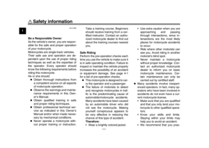 8
8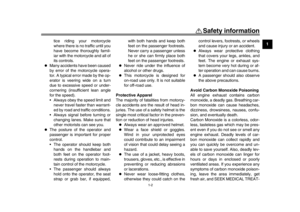 9
9 10
10 11
11 12
12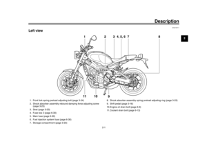 13
13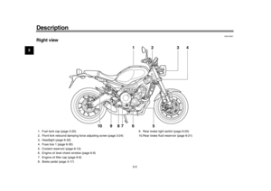 14
14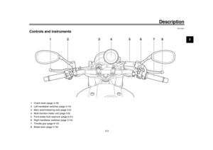 15
15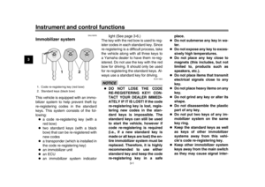 16
16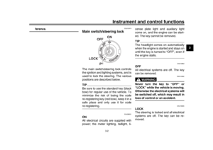 17
17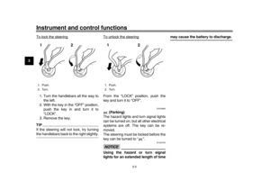 18
18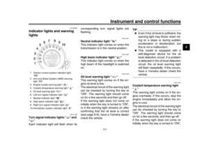 19
19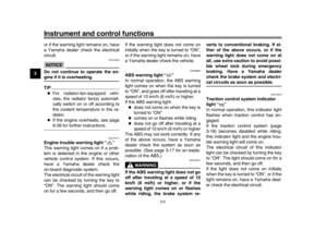 20
20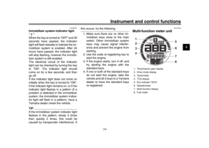 21
21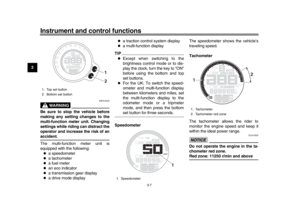 22
22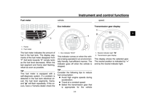 23
23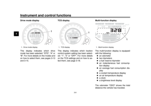 24
24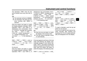 25
25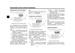 26
26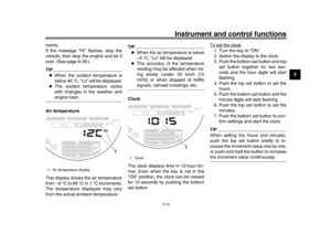 27
27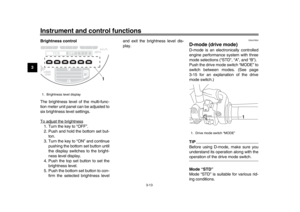 28
28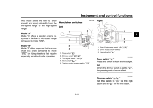 29
29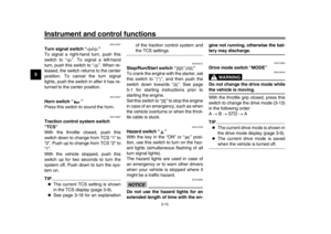 30
30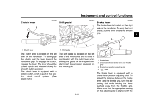 31
31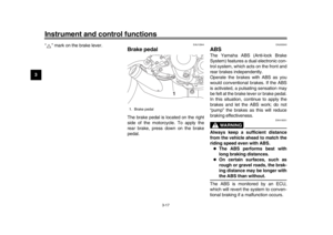 32
32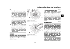 33
33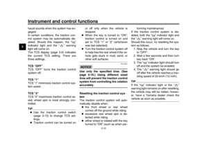 34
34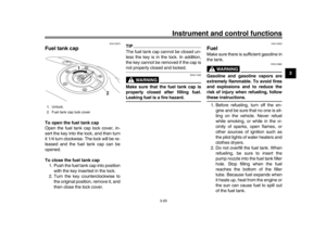 35
35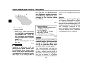 36
36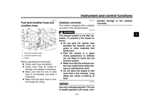 37
37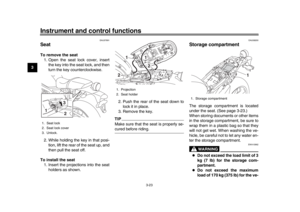 38
38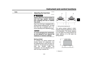 39
39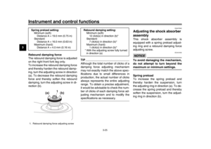 40
40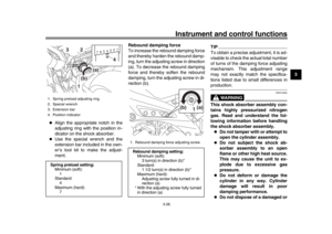 41
41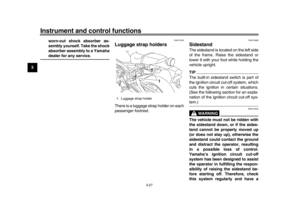 42
42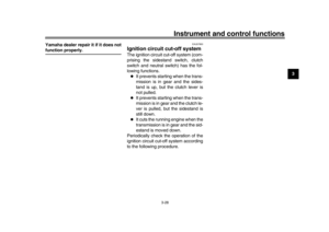 43
43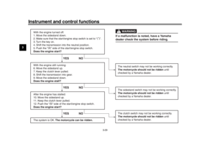 44
44 45
45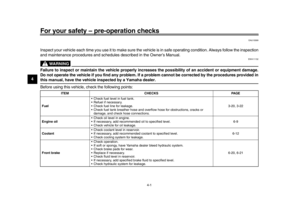 46
46 47
47 48
48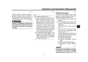 49
49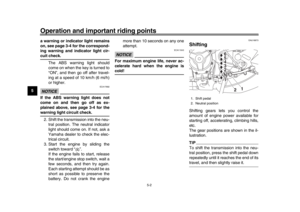 50
50 51
51 52
52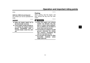 53
53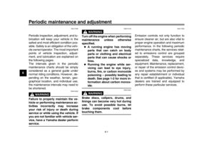 54
54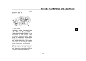 55
55 56
56 57
57 58
58 59
59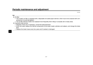 60
60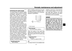 61
61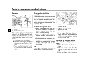 62
62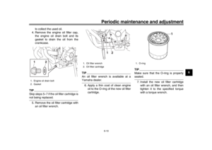 63
63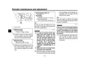 64
64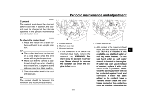 65
65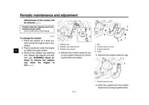 66
66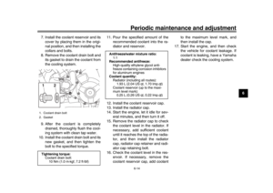 67
67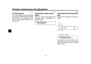 68
68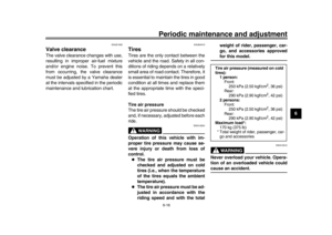 69
69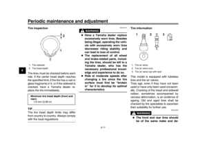 70
70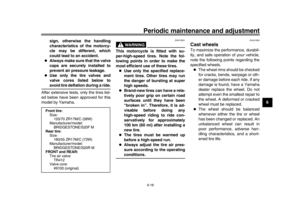 71
71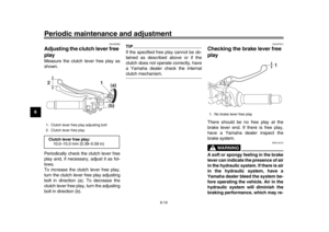 72
72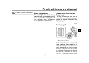 73
73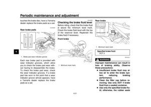 74
74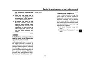 75
75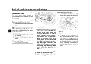 76
76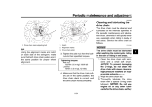 77
77 78
78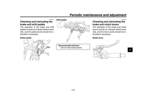 79
79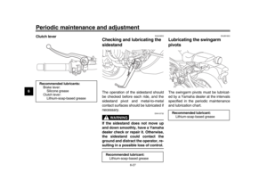 80
80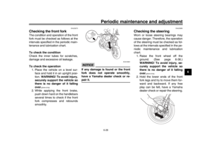 81
81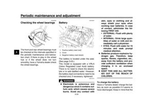 82
82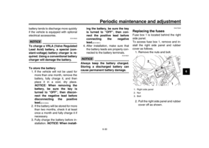 83
83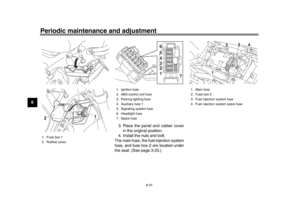 84
84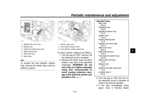 85
85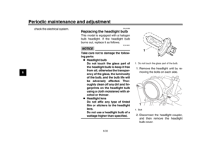 86
86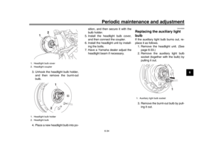 87
87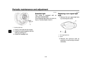 88
88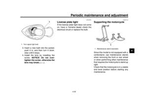 89
89 90
90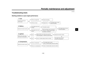 91
91 92
92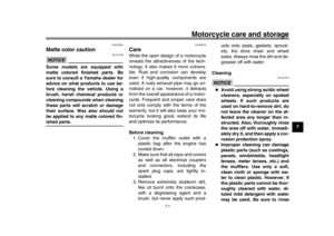 93
93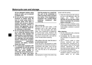 94
94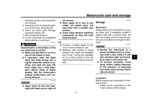 95
95 96
96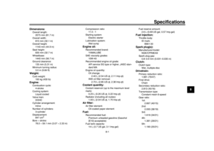 97
97 98
98 99
99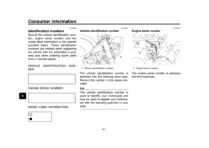 100
100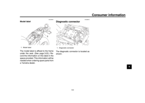 101
101 102
102 103
103 104
104 105
105