Page 129 of 426

CHASSIS
3-31
• When refilling, be careful that water does not enter the brake fluid reservoir. Water
will significantly lower the boiling point of
the brake fluid and could cause vapor
lock.
ECA
NOTICE
Brake fluid may damage painted surfaces
and plastic parts. Therefore, always clean
up any spilt brake fluid immediately.
EAS2GC1110ADJUSTING THE DRIVE CHAIN SLACKECA
NOTICE
A drive chain that is too tight will overload
the engine and other vital parts, and one
that is too loose can skip and damage the
swingarm or cause an accident. Therefore,
keep the drive chain slack within the speci-
fied limits.
1. Use a suitable stand to raise the rear wheel off the ground.
EWA
WARNING
Securely support the vehicle so that there is
no danger of it falling over.
2. Shift the transmission into the neutral posi-
tion.
3. Pull the drive chain up above the drive chain guide installation bolt with a force of about
50 N (5.0 kgf, 36 lbf).
4. Check: • Drive chain slack “a”
Out of specification Regulate.
TIP
Measure drive chain slack between the drive
chain guide and the bottom of the chain as
shown. 5. Adjust:
• Drive chain slack
▼▼▼▼▼▼▼▼▼▼▼▼▼▼▼▼▼▼▼▼▼▼▼▼▼▼▼▼▼▼▼▼
a. Loosen the wheel axle nut “1”.
b. Loosen both locknuts “2”.
c. Turn the adjusting bolt “3” in direction “a” or “b” until the specified drive chain slack is ob-
tained.
TIP
• To maintain the proper wheel alignment, ad-just both sides evenly.
• Push the rear wheel forward to make sure that
there is no clearance between the swingarm
end plates and the ends of the swingarm.
d. Tighten the locknut.
e. Tighten the wheel axle nut.
▲▲▲▲▲▲▲▲▲▲▲▲▲▲▲▲▲▲▲▲▲▲▲▲▲▲▲▲▲▲▲▲
EAS2GC1111CHECKING THE FRONT FORK LEGS
1. Stand the vehicle upright on a level surface.
EWA
WARNING
Securely support the vehicle so that there is
no danger of it falling over.
2. Check: • Inner tubeDamage/scratches Replace.
• Front fork leg (s) Oil leaks between inner tube and outer tube
Replace the oil seal.
Drive chain slack (on a suitable
stand)
50.0–60.0 mm (1.97–2.36 in)
a
Direction “a”The drive chain slack decreases.
Direction “b” The drive chain slack increases.
Locknut21 Nm (2.1 m·kgf, 15 ft·lbf)
Wheel axle nut 125 Nm (12.5 m·kgf, 90 ft·lbf)
1
32
a
b
T R..
T R..
Page 130 of 426

CHASSIS
3-32
3. Hold the vehicle upright and apply the front brake.
4. Check:
• Front fork operationPush down hard on the handlebar several
times and check if the front fork rebounds
smoothly.
Unsmooth operation Correct or replace.
Refer to “FRONT FORK” on page 5-40.
EAS2GC1112CHECKING THE FRONT FORK PROTEC-
TOR GUIDE
1. Check:
• Protector guide “1”Out of specification Replace.
TIP
The protector guide reaches the limit of its use
when it is worn down to the same height “a” as
of the outer tube circumference.
EAS2GC1113CLEANING THE FRONT FORK OIL SEAL
AND DUST SEAL
1. Remove:
•Protector
• Dust seal “1”
ECA
NOTICE
Be careful not to damage the dust seal and
the inner tube by a driver. 2. Clean:
• Dust seal “a”
• Oil seal “b”
TIP
• Clean the dust seal and oil seal after every
run.
• Apply lithium-soap-based grease on the inner
tube.
EAS2GC1114AIR BLEEDING FROM FRONT FORK
TIP
If the front fork initial movement feels stiff dur-
ing a run, relieve the front fork internal pres-
sure.
1. Use a suitable stand to raise the front wheel off the ground.
EWA
WARNING
Securely support the vehicle so that there is
no danger of it falling over.
2. Remove the air bleed screw “1” and release the internal pressure from the front fork.
1
a
1
LS
a
b
Page 131 of 426

CHASSIS
3-33
3. Tighten:• Air bleed screw
EAS2GC1115ADJUSTING THE FRONT FORK LEGSEWA
WARNING
• Always adjust the left and right front forks evenly. If this is not done, the vehicle may
have poor stability.
• Securely support the vehicle so that there
is no danger of it falling over.
Rebound damping
ECA
NOTICE
Do not turn the adjuster forcibly beyond its
adjusting range.
1. Adjust: • Rebound damping
▼▼▼▼▼▼▼▼▼▼▼▼▼▼▼▼▼▼▼▼▼▼▼▼▼▼▼▼▼▼▼▼
a. Turn the adjuster “1” in the direction of “a” or
“b” to make an adjustment.
▲▲▲▲▲▲▲▲▲▲▲▲▲▲▲▲▲▲▲▲▲▲▲▲▲▲▲▲▲▲▲▲
Compression dampingECA
NOTICE
Do not turn the adjuster forcibly beyond its
adjusting range.
1. Adjust:• Compression damping
▼▼▼▼▼▼▼▼▼▼▼▼▼▼▼▼▼▼▼▼▼▼▼▼▼▼▼▼▼▼▼▼
a. Turn the adjuster “1” in the direction of “a” or “b” to make an adjustment.
▲▲▲▲▲▲▲▲▲▲▲▲▲▲▲▲▲▲▲▲▲▲▲▲▲▲▲▲▲▲▲▲
Air bleed screw1.3 Nm (0.13 m·kgf, 0.94 ft·lbf)
Direction “a” Rebound damping is increased (sus-
pension is harder).
Direction “b” Rebound damping is decreased (sus-
pension is softer).
Rebound damping adjusting posi-
tionsMaximumFully turned in
Standard 11 clicks out*
Minimum 20 clicks out*
* With the adjuster fully turned in
T R..
1
Direction “a” Compression damping is increased
(suspension is harder).
Direction “b” Compression damping is decreased
(suspension is softer).
Compression damping adjusting
positions Maximum Fully turned in
Standard 13 clicks out*
Minimum 20 clicks out*
* With the adjuster fully turned in
1
a b
ab
1
Page 132 of 426

CHASSIS
3-34
EAS2GC1116CHECKING THE SWINGARM OPERATION
1. Check:• Swingarm smooth action
• Swingarm free playRefer to “SWINGARM” on page 5-65.
EAS2GC1117CHECKING THE REAR SUSPENSION
1. Stand the vehicle upright on a level surface.
EWA
WARNING
Securely support the vehicle so that there is
no danger of it falling over.
2. Check:• Rear shock absorber assemblyGas leaks/oil leaks Replace the rear
shock absorber assembly.
Refer to “REAR SHOCK ABSORBER AS-
SEMBLY” on page 5-58.
3. Check: • Rear shock absorber assembly smooth ac-tion
• Rear suspension link smooth action Sit astride the seat and shake your body up
and down several times to check whether
the rear shock absorber assembly operates
smoothly.
Unsmooth operation Correct or replace.
Refer to “REAR SHOCK ABSORBER AS-
SEMBLY” on page 5-58.
EAS2GC1118ADJUSTING THE REAR SHOCK ABSORB-
ER ASSEMBLY
Use a suitable stand to raise the rear wheel off
the ground.
EWA
WARNING
Securely support the vehicle so that there is
no danger of it falling over. Spring preload
ECA
NOTICE
Do not turn the adjuster forcibly beyond its
adjusting range.
1. Remove:
• Rear frameRefer to “REAR SHOCK ABSORBER AS-
SEMBLY” on page 5-58.
2. Adjust: • Spring preload
▼▼▼▼▼▼▼▼▼▼▼▼▼▼▼▼▼▼▼▼▼▼▼▼▼▼▼▼▼▼▼▼
a. Loosen the locknut “1”.
b. Loosen the adjuster “2” until there is some clearance between the spring and the ad-
juster.
c. Measure the spring free length “a”.
d. Turn the adjuster in the direction of “b” or “c” to make an adjustment.
Direction “b”Spring preload is increased (suspen-
sion is harder).
Direction “c” Spring preload is decreased (suspen-
sion is softer).
Spring preload adjusting positionsMinimum Position in which the spring is
turned in 1.5 mm (0.06 in) from
its free length.
Standard Position in which the spring is
turned in 12 mm (0.47 in) from its
free length.
Maximum Position in which the spring is
turned in 18 mm (0.71 in) from its
free length.
Page 133 of 426

CHASSIS
3-35
TIP
• Be sure to remove all dirt and mud from around the locknut and adjusting ring before
adjustment.
• The length of the spring (installed) changes
1.5 mm (0.06 in) per turn of the adjusting ring.
e. Tighten the locknut.
▲▲▲▲▲▲▲▲▲▲▲▲▲▲▲▲▲▲▲▲▲▲▲▲▲▲▲▲▲▲▲▲
3. Install: • Rear frameRefer to “REAR SHOCK ABSORBER AS-
SEMBLY” on page 5-58.
Rebound damping
ECA
NOTICE
Do not turn the adjuster forcibly beyond its
adjusting range.
1. Adjust: • Rebound damping
▼▼▼▼▼▼▼▼▼▼▼▼▼▼▼▼▼▼▼▼▼▼▼▼▼▼▼▼▼▼▼▼
a. Turn the adjuster “1” in the direction of “a” or “b” to make an adjustment.
▲▲▲▲▲▲▲▲▲▲▲▲▲▲▲▲▲▲▲▲▲▲▲▲▲▲▲▲▲▲▲▲
Compression damping (for fast compres-
sion damping)
ECA
NOTICE
Do not turn the adjuster forcibly beyond its
adjusting range.
1. Adjust:
• Compression damping (for fast compression damping)
▼▼▼▼▼▼▼▼▼▼▼▼▼▼▼▼▼▼▼▼▼▼▼▼▼▼▼▼▼▼▼▼
a. Turn the adjuster “1” in the direction of “a” or “b” to make an adjustment.
Locknut
30 Nm (3.0 m·kgf, 22 ft·lbf)
Direction “a” Rebound damping is increased (sus-
pension is harder).
Direction “b” Rebound damping is decreased (sus-
pension is softer).
c
b
T R..
Rebound damping adjusting posi-
tions Maximum Fully turned in
Standard 14 clicks out*
Minimum 30 clicks out*
* With the adjuster fully turned
Direction “a”Compression damping is increased
(suspension is harder).
Direction “b” Compression damping is decreased
(suspension is softer).
Compression damping setting
(for fast compression damping)Maximum Fully turned in
Standard 1-3/4 turns out*
Minimum 2 turns out*
* With the adjuster fully turned
a
b
1
Page 134 of 426

CHASSIS
3-36
▲▲▲▲▲▲▲▲▲▲▲▲▲▲▲▲▲▲▲▲▲▲▲▲▲▲▲▲▲▲▲▲
Compression damping (for slow compres-
sion damping)
ECA
NOTICE
Do not turn the adjuster forcibly beyond its
adjusting range.
1. Adjust:• Compression damping (for slow compres-
sion damping)
▼▼▼▼▼▼▼▼▼▼▼▼▼▼▼▼▼▼▼▼▼▼▼▼▼▼▼▼▼▼▼▼
a. Turn the adjuster “1” in the direction of “a” or “b” to make an adjustment.
▲▲▲▲▲▲▲▲▲▲▲▲▲▲▲▲▲▲▲▲▲▲▲▲▲▲▲▲▲▲▲▲
EAS2GC1119CHECKING THE TIRES
1. Measure:
• Tire pressureOut of specification Regulate.
TIP
• Check the tire while it is cold.
• Loose bead stoppers allow the tire to slip off
its position on the rim when the tire pressure
is low.
• If the tire valve stem is found tilted, the tire is
considered to be slipping off its position. Cor-
rect the tire position.
EAS2GC1120CHECKING AND TIGHTENING THE
SPOKES
1. Check:• SpokesBend/damage Replace.
Loose Tighten.
TIP
A tight spoke will emit a clear, ringing tone; a
loose spoke will sound flat.
Direction “a”
Compression damping is increased
(suspension is harder).
Direction “b” Compression damping is decreased
(suspension is softer).
Compression damping setting
(for slow compression damping)MaximumFully turned in
Standard 10 clicks out*
Minimum 20 clicks out*
* With the adjuster fully turned in
1 a
b
1
ba
Tire air pressure (measured on cold
tires)
Front 100 kPa (1.00 kgf/cm
2, 15 psi)
Rear 100 kPa (1.00 kgf/cm
2, 15 psi)
Page 135 of 426

CHASSIS
3-37
2. Tighten:• SpokesUse a spoke nipple wrench “1” for tighten-
ing.
TIP
• Do not give a half turn (180 °) or more for one tightening.
• Make sure that tightening after a break-in is done until the initial looseness in nipples dis-
appears.
• Make sure that tightening is done in stages,
not at a time.
EAS2GC1121CHECKING THE WHEELS
1. Check: • Wheel(s)Damage/out-of-round Replace.
EWA
WARNING
Never attempt to make any repairs to the
wheel.
TIP
After replacing a tire or a wheel, always bal-
ance the wheel.
EAS2GC1122CHECKING THE WHEEL BEARINGS
1. Check:
• Wheel bearingsRefer to “CHECKING THE FRONT WHEEL”
on page 5-5 and “CHECKING THE REAR
WHEEL” on page 5-10.
EAS2GC1123CHECKING AND ADJUSTING THE STEER-
ING HEAD
1. Use a suitable stand to raise the front wheel off the ground.
EWA
WARNING
Securely support the vehicle so that there is
no danger of it falling over.
2. Check:• Steering head
Grasp the bottom of the front fork legs and
gently rock the front fork.
Blinding/looseness Adjust the steering
head.
3. Remove: • Handlebar
Refer to “HANDLEBAR” on page 5-33.
• Upper bracket Refer to “STEERING HEAD” on page 5-53.
4. Adjust: • Steering head
▼▼▼▼▼▼▼▼▼▼▼▼▼▼▼▼▼▼▼▼▼▼▼▼▼▼▼▼▼▼▼▼
a. Remove the washer “1”.
b. After loosening the ring nut “2” with a steer- ing nut wrench “3”, tighten it to the specified
torque.
TIP
• Set the torque wrench at a right angle to the
steering nut wrench.
• Move the steering to the left and right a couple
of times to check that it moves smoothly.
Spoke nipple wrench (6–7)
90890-01521
Spoke nipple wrench (6–7) YM-01521
Spokes 2.5 Nm (0.25 m·kgf, 1.8 ft·lbf)
1
T R..
1
3
2
Page 136 of 426

CHASSIS
3-38
c. Turn the front fork to the right and left a few times, and make sure that the steering ro-
tates smoothly. If it does not turn smoothly,
remove the lower bracket and check the up-
per and lower bearings.
Refer to “STEERING HEAD” on page 5-53.
d. Loosen the ring nut fully turn and then tight- en it to specification with a steering nut
wrench.
EWA
WARNING
Do not overtighten the lower ring nut.
e. Check the steering head for looseness or binding by turning the front fork all the way in
both directions. If any binding is felt, remove
the lower bracket and check the upper and
lower bearings.
Refer to “STEERING HEAD” on page 5-53.
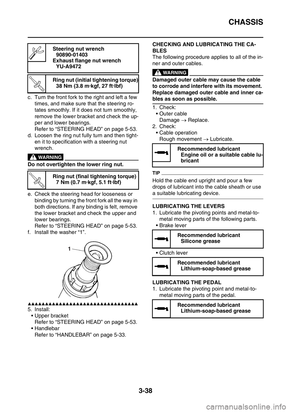
f. Install the washer “1”.
▲▲▲▲▲▲▲▲▲▲▲▲▲▲▲▲▲▲▲▲▲▲▲▲▲▲▲▲▲▲▲▲
5. Install: • Upper bracketRefer to “STEERING HEAD” on page 5-53.
• Handlebar
Refer to “HANDLEBAR” on page 5-33.
EAS2GC1124CHECKING AND LUBRICATING THE CA-
BLES
The following procedure applies to all of the in-
ner and outer cables.
EWA
WARNING
Damaged outer cable may cause the cable
to corrode and interfere with its movement.
Replace damaged outer cable and inner ca-
bles as soon as possible.
1. Check:• Outer cableDamage Replace.
2. Check: • Cable operationRough movement Lubricate.
TIP
Hold the cable end upright and pour a few
drops of lubricant into the cable sheath or use
a suitable lubricating device.
EAS2GC1125LUBRICATING THE LEVERS
1. Lubricate the pivoting points and metal-to-
metal moving parts of the following parts.
•Brake lever
• Clutch lever
EAS2GC1126LUBRICATING THE PEDAL
1. Lubricate the pivoting point and metal-to-
metal moving parts of the pedal.
Steering nut wrench
90890-01403
Exhaust flange nut wrench YU-A9472
Ring nut (initial tightening torque) 38 Nm (3.8 m·kgf, 27 ft·lbf)
Ring nut (final tightening torque) 7 Nm (0.7 m·kgf, 5.1 ft·lbf)
T R..
T R..
1
Recommended lubricantEngine oil or a suitable cable lu-
bricant
Recommended lubricant Silicone grease
Recommended lubricant Lithium-soap-based grease