Page 57 of 126

Instrument and control functions
3-43
3
EAU55424
A djustin g the front an d rear
suspension
This model is equipped with an elec-
tronically adjustable suspension sys-
tem. The preload of the rear shock
absorber and the damping forces of
both the front fork and rear shock ab-
sorber can be adjusted.
WARNING
EWA12423
Be sure to stop the vehicle before
makin g any settin g chan ges to the
multi-function meter unit. Chang ing
settin gs while ri din g can d istract the
operator an d increase the risk of an
acci dent.
Preloa d
When riding with luggage or a passen-
ger, use the preload adjusting function
to adjust the suspension system to
match the load. There are 4 preload
settings.
TIP
The preload adjusting function will
appear only when the engine is
running.
Changing the preload setting will
also adjust the front and rear sus-
pension damping forces accord-
ingly. See “Damping force” on
page 3-45 for more information.
About cold temperature opera-
tion:
• When using the preload adjust- ing function, there should be no
weight on the vehicle.
• When using the preload adjust- ing function at ambient temper-
atures near or below 0 °C (32
°F), to protect the preload ad- justing function motor, the elec-
tronically adjustable suspension
system warning light may come
on.
• The suspension will still operate as normal, only the preload ad-
justing function cannot be used.
• To reset the electronically ad- justable suspension system
warning light, wait approximate-
ly 6 minutes and then turn the
key to “OFF” or immediately
turn the key to “OFF” and then
wait 6 minutes.
• If the electronically adjustable suspension system warning
light remains on, have a
Yamaha dealer check the sus- pension system.
To adjust the preload
1. Turn the key to “ON”, start the en- gine, and then shift the transmis-
sion into neutral.
2. Push the menu switch “MENU” to switch the function display to the
preload adjusting function.
1. Function display
2. Preload adjusting function
3. Preload setting pictogram
GEAR
N
1
3
2
UB95E0E0.book Page 43 Friday, February 19, 2016 2:15 PM
Page 58 of 126

Instrument and control functions
3-44
3
3. Use the select switch to select thedesired preload setting pictogram.
Select the suitable setting from
the following 4 pictograms ac-
cording to your load condition.
While the preload is being adjust-
ed, the information display will
show a group of dots moving in a
circle. Once the selected picto-
gram returns, the preload adjust-
ment is complete. While the preload is being adjusted,
the information display may change as
follows.
If the key is turned to “OFF” or the
engine is stopped while the pre-
load is being set, the following
preload setting pictogram will
flash to alert you that the current
preload setting does not match
the pictogram. If this occurs, ad-
just the preload again.
If the vehicle starts moving, the
following preload setting picto-
gram will flash to alert you that the
current preload setting does not
match the pictogram. If this oc-
curs, stop the vehicle and adjust
the preload again.1. Menu switch “MENU”
2. Select switch “ / ”
1. Solo riding
2. Solo riding and luggage
3. Passenger riding
4. Passenger riding and luggage
1
2
12
34
GEAR
N
GEAR
N
GEAR
N
GEAR
N
UB95E0E0.book Page 44 Friday, February 19, 2016 2:15 PM
Page 59 of 126

Instrument and control functions
3-45
3
If the preload is adjusted repeat-
edly, the preload setting picto-
gram will flash 4 times and the
preload cannot be adjusted. Wait
approximately 6 minutes for the
preload adjusting function motor
to cool down, and then try adjust-
ing the preload again.
Dampin g force
Within each preload setting there are 3
damping force settings: “HARD”
(hard), “STD” (standard) and “SOFT”
(soft). When the preload setting is
changed, the damping force settings
will change accordingly. (The electron-
ically adjustable suspension system
will automatically adjust to the damp-
ing force settings last set for that pre-
load setting.) To further finely adjust
the damping force, each damping
force setting can be set to 7 different
levels.
TIP
If the preload setting was not complet-
ed correctly: The damping force setting and
setting level will flash 4 times and
cannot be adjusted if you try to
adjust them while the vehicle is
stopped.
The preload setting pictogram will
flash and the damping force can-
not be adjusted if you try to adjust
it while the vehicle is moving.
Be sure that the preload has been set
correctly before adjusting the damping
force.
To adjust the damping force and
damping force setting level
1. Turn the key to “ON”.
2. Push the menu switch “MENU” to switch the function display to the
damping force adjusting function.
GEAR
1
HARD+3
GEAR
N
GEAR
N
GEAR
N
1. Damping force setting
2. Damping force setting level
GEAR
N
HARD+3
2
1
UB95E0E0.book Page 45 Friday, February 19, 2016 2:15 PM
Page 60 of 126

Instrument and control functions
3-46
3
3. Use the select switch to select“HARD”, “STD” or “SOFT”.
4. Push the menu switch “MENU”.
5. Use the select switch to select the desired level for the damping
force setting.
TIP
The damping force setting can be set to
7 levels (+3, +2, +1, 0, –1, –2 and –3).
“+3” is the hardest level and “–3” is the
softest level.
6. Push the menu switch “MENU”.
If the vehicle moves while you are ad-
justing the damping force, the informa-
tion display will change to the display
mode.
WARNING
EWA16421
The rear shock ab sorber assem bly
contains hi ghly pressurize d nitro gen
g as. Read and un derstan d the fol-
lowin g information before han dlin g
the shock a bsor ber assem bly.
Do not tamper with or attempt
to open the cylind er assembly.
Do not su bject the shock a b-
sor ber assem bly to an open
flame or other hi gh heat source.
This may cause the unit to ex-
plo de due to excessive g as
pressure.
1. Function display
2. Damping force adjusting function
1. Damping force setting
1. Damping force setting level
GEAR
N
STD 0
1
2
GEAR
N
HARD 01
GEAR
N
HARD
+31
1. Damping force adjusting function
2. Damping force setting
3. Preload setting pictogram
GEAR
N
HARD+3
GEAR
1
HARD+3
1
2
3
UB95E0E0.book Page 46 Friday, February 19, 2016 2:15 PM
Page 61 of 126

Instrument and control functions
3-47
3
Do not deform or damag e the
cylin der in any way. Cylin der
d amag e will result in poor
d ampin g performance.
Do not d ispose of a damag ed or
worn-out shock a bsor ber as-
sem bly yourself. Take the shock
a b sor ber assem bly to a Yamaha
d ealer for any service.
EAU55592
Si destan d
The sidestand is located on the left
side of the frame. Raise the sidestand
or lower it with your foot while holding
the vehicle upright.
TIP
The built-in sidestand switch is
part of the ignition circuit cut-off
system, which cuts the ignition in
certain situations. (See the follow-
ing section for an explanation of
the ignition circuit cut-off system.)
The sidestand switch is also part
of the YCC-S system. Shifting out
of neutral is impossible when the
sidestand is down.
WARNING
EWA10242
The vehicle must not be ri dden with
the si destan d d own, or if the si de-
stan d cannot b e properly move d up
(or does not stay up), otherwise the
si destan d coul d contact the g round
an d d istract the operator, resultin g
in a possi ble loss of control.
Yamaha’s ig nition circuit cut-off
system has been desi gne d to assist
the operator in fulfillin g the respon-
si bility of raisin g the si destan d b e-
fore startin g off. Therefore, check
this system re gularly an d have a
Yamaha dealer repair it if it does not
function properly.
UB95E0E0.book Page 47 Friday, February 19, 2016 2:15 PM
Page 62 of 126
Instrument and control functions
3-48
3
EAU68770
Ig nition circuit cut-off system
The ignition circuit cut-off system
(comprising the sidestand switch and
brake light switches) has the following
functions.
It prevents starting when the side-
stand is up, but neither brake is applied.
It prevents starting when either
brake is applied, but the sidestand
is still down.
It cuts the running engine when
the sidestand is moved down.
Periodically check the operation of the
ignition circuit cut-off system accord-
ing to the following procedure.
UB95E0E0.book Page 48 Friday, February 19, 2016 2:15 PM
Page 63 of 126

Instrument and control functions
3-49
3
With the engine turned off:
1. Place the vehicle on the centerstand.
2.
Move the sidestand down.
3. Make sure that the start/engine stop switch is set to “ ”.
4. Turn the key to “ON”.
5. Shift the transmission into the neutral position.
6. Keep the front or rear brake applied.
7.
Push the “ ” side of the start/engine
stop switch.
Does the engine start?
With the engine still running:
8. Move the sidestand up.
9. Shift the transmission into gear.
10. Move the sidestand down.
Does the engine stall?
After the engine has stalled:
11. Move the sidestand up.
12. Release the brake.
13.
Push the “ ” side of the
start/engine stop switch.
Does the engine start?
The system is OK. The motorcycle can
be ridden.
The neutral switch, a brake light switch
or the YCC-S system may not be
working correctly.
The motorcycle should not be ridden
until checked by a Yamaha dealer.
The sidestand switch may not be
working correctly.
The motorcycle should not be ridden
until checked by a Yamaha dealer.
A brake light switch may not be working
correctly.
The motorcycle should not be ridden
until checked by a Yamaha dealer.
WARNING
The vehicle must be placed on the centerstand during this inspection.
If a malfunction is noted, have a Yamaha dealer check the system
before riding.
TIP
The traction control system
indicator/warning light “TCS” may come
on, but this is not a malfunction.
YES NO
YESNO
NOYES
UB95E0E0.book Page 49 Friday, February 19, 2016 2:15 PM
Page 64 of 126

Instrument and control functions
3-50
3
EAU39656
Auxiliary DC jack
WARNING
EWA14361
To prevent electrical shock or short-
circuitin g, make sure that the cap is
installe d when the auxiliary DC jack
is not b eing use d.
NOTICE
ECA15432
The accessory connecte d to the
auxiliary DC jack shoul d not b e used
with the en gine turne d off, an d the
loa d must never exceed 30 W (2.5 A),
otherwise the fuse may blow or the
b attery may d ischarge.
This vehicle is equipped with an auxil-
iary DC jack in the accessory box.
A 12-V accessory connected to the
auxiliary jack can be used when the
key is in the “ON” position and should
only be used when the engine is run-
ning.
To use the auxiliary DC jack
1. Open the accessory box lid. (See page 3-39.)
2. Turn the key to “OFF”.
3. Remove the auxiliary DC jack cap.
4. Turn the accessory off. 5. Insert the accessory plug into the
auxiliary DC jack.
6. Turn the key to “ON”, and then start the engine. (See page 5-2.)
7. Turn the accessory on.
1. Auxiliary DC jack cap
1
1. Auxiliary DC jack
1
UB95E0E0.book Page 50 Friday, February 19, 2016 2:15 PM
 1
1 2
2 3
3 4
4 5
5 6
6 7
7 8
8 9
9 10
10 11
11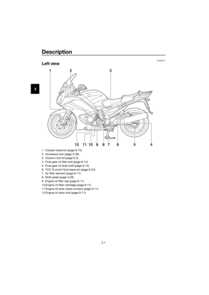 12
12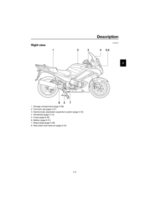 13
13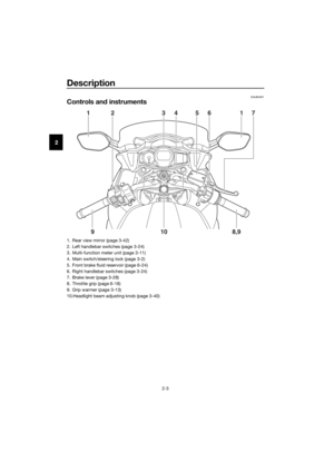 14
14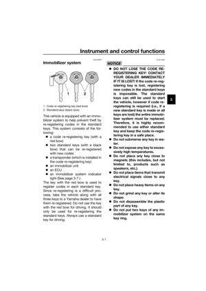 15
15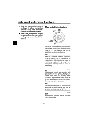 16
16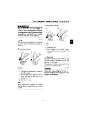 17
17 18
18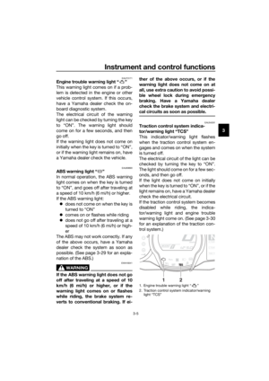 19
19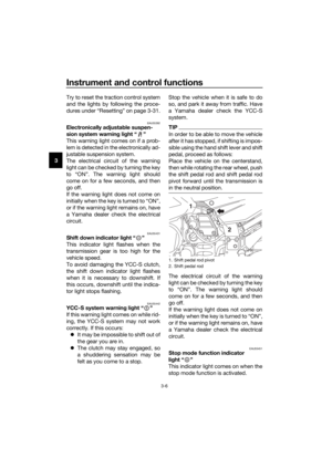 20
20 21
21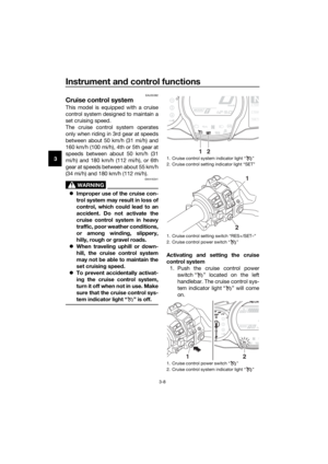 22
22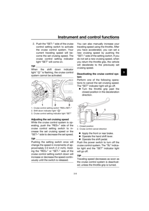 23
23 24
24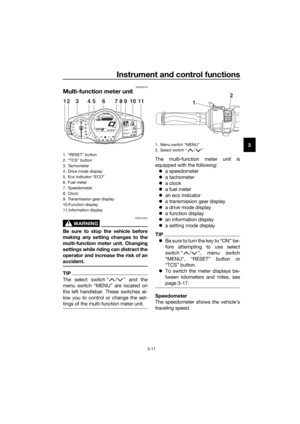 25
25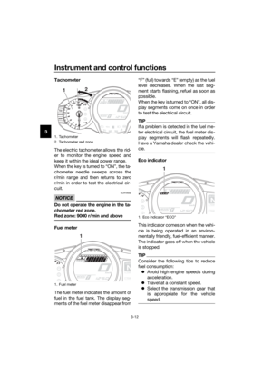 26
26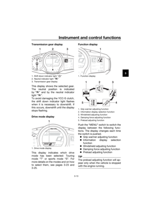 27
27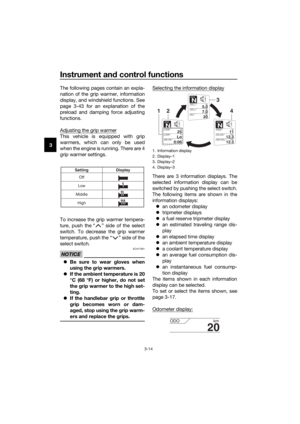 28
28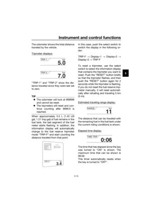 29
29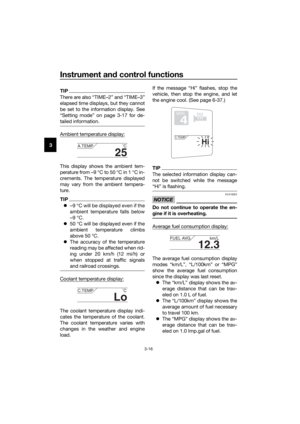 30
30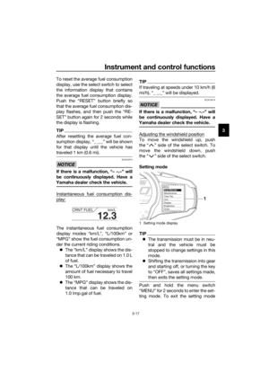 31
31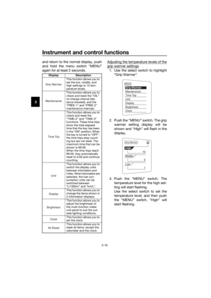 32
32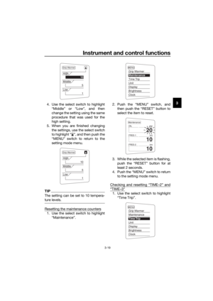 33
33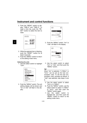 34
34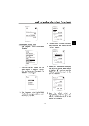 35
35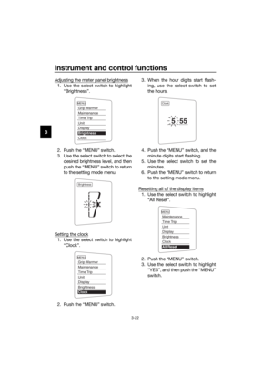 36
36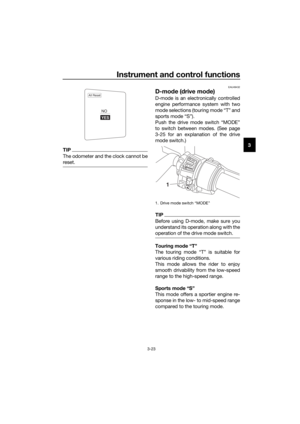 37
37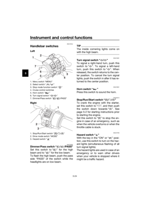 38
38 39
39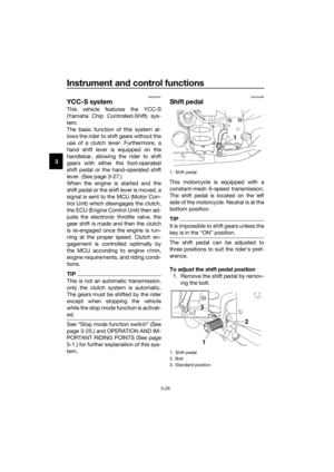 40
40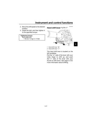 41
41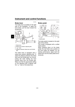 42
42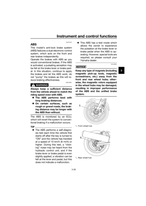 43
43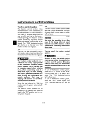 44
44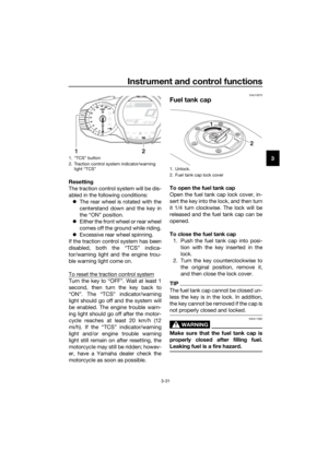 45
45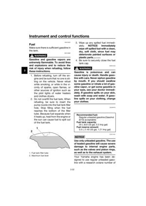 46
46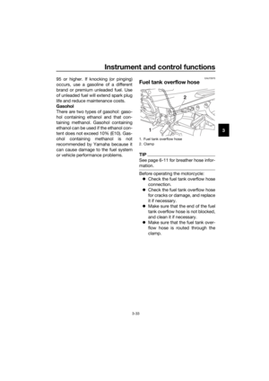 47
47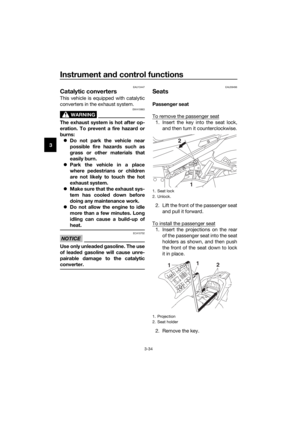 48
48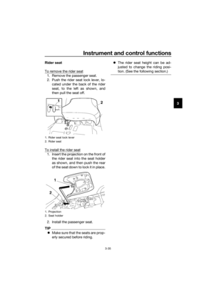 49
49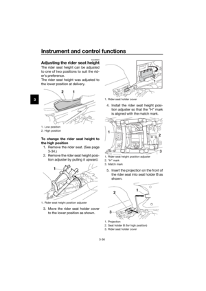 50
50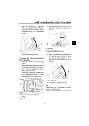 51
51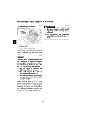 52
52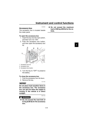 53
53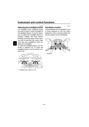 54
54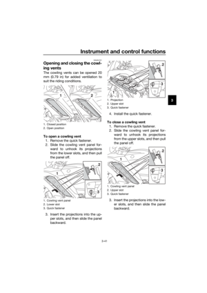 55
55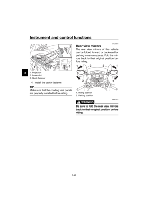 56
56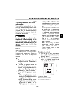 57
57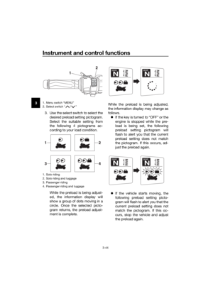 58
58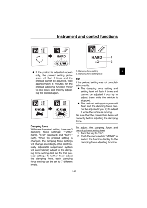 59
59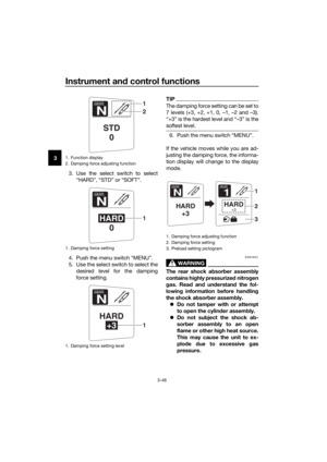 60
60 61
61 62
62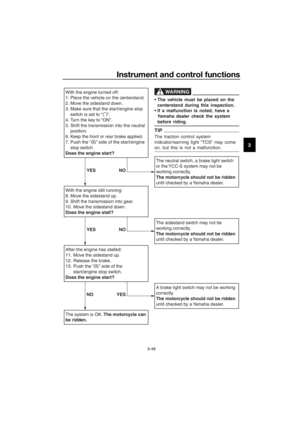 63
63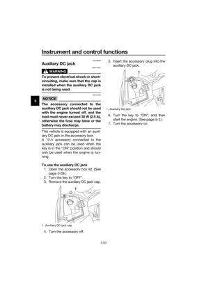 64
64 65
65 66
66 67
67 68
68 69
69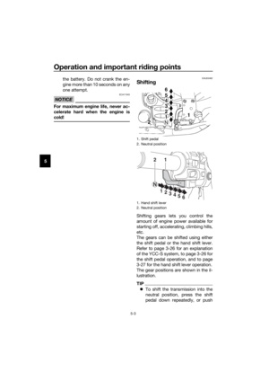 70
70 71
71 72
72 73
73 74
74 75
75 76
76 77
77 78
78 79
79 80
80 81
81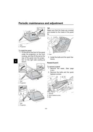 82
82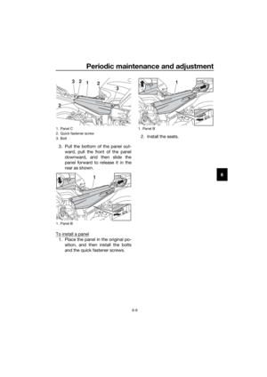 83
83 84
84 85
85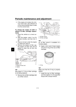 86
86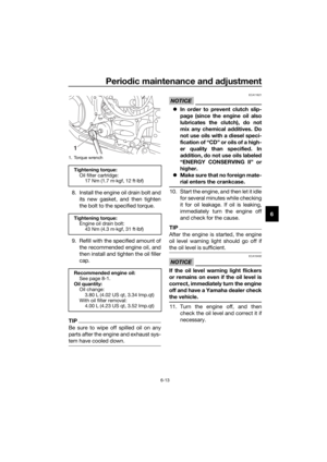 87
87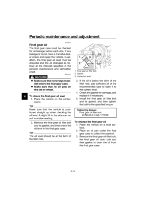 88
88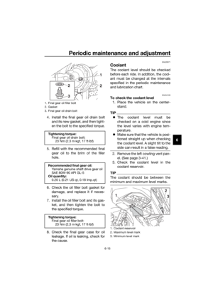 89
89 90
90 91
91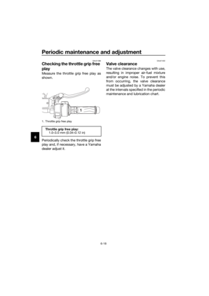 92
92 93
93 94
94 95
95 96
96 97
97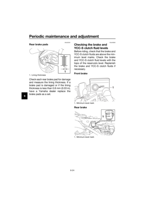 98
98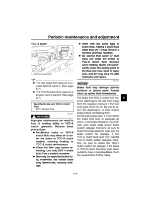 99
99 100
100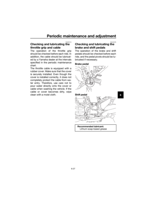 101
101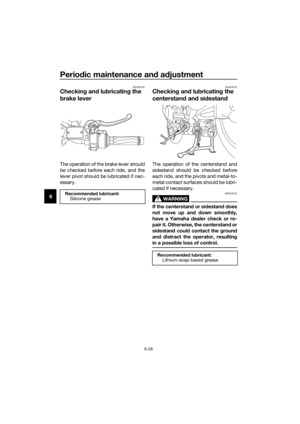 102
102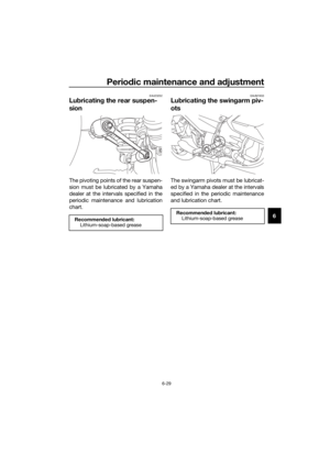 103
103 104
104 105
105 106
106 107
107 108
108 109
109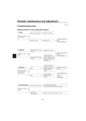 110
110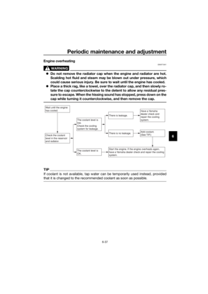 111
111 112
112 113
113 114
114 115
115 116
116 117
117 118
118 119
119 120
120 121
121 122
122 123
123 124
124 125
125 has the following
funct")