2016 YAMAHA FJR1300AS key
[x] Cancel search: keyPage 44 of 126

Instrument and control functions
3-30
3
EAU54271
Traction control system
The traction control system helps
maintain traction when accelerating on
slippery surfaces, such as unpaved or
wet roads. If sensors detect that the
rear wheel is starting to slip (uncon-
trolled spinning), the traction control
system assists by regulating engine
power as needed until traction is re-
stored. The “TCS” indicator/warning
light flashes to let the rider know that
traction control has engaged.
TIP
The rider may also notice slight chang-
es in engine and exhaust sounds when
the traction control system is engaged.
WARNING
EWA15432
The traction control system is not a
su bstitute for rid ing appropriately
for the con ditions. Traction control
cannot prevent loss of traction due
to excessive speed when entering
turns, when acceleratin g har d at a
sharp lean an gle, or while brakin g,
an d cannot prevent front wheel slip-
pin g. As with any motorcycle, ap-
proach surfaces that may b e
slippery with caution an d avoi d es-
pecially slippery surfaces.
When the key is turned to “ON”, the
traction control system automatically
turns on.
The traction control system can be
turned on or off manually only when the
key is in the “ON” position and the mo-
torcycle is stopped.
TIP
Turn the traction control system off to
help free the rear wheel if the motorcy-
cle gets stuck in mud, sand, or other
soft surfaces.
NOTICE
ECA16801
Use only the specifie d tires. (See
pa ge 6-19.) Usin g different sized
tires will prevent the traction control
system from controllin g tire rotation
accurately.
Turnin g on/off the traction control
system
WARNING
EWA15441
Be sure to stop the vehicle before
makin g any settin g chan ges to the
traction control system. Chan gin g
settin gs while ri din g can d istract the
operator an d increase the risk of an
acci dent.
To turn off the traction control system,
push the “TCS” button on the multi-
function meter unit for at least 2 sec-
onds. The “TCS” indicator/warning
light will come on.
To turn on the traction control system,
push the “TCS” button again. The
“TCS” indicator/warning light will go
off.
UB95E0E0.book Page 30 Friday, February 19, 2016 2:15 PM
Page 45 of 126

Instrument and control functions
3-31
3
Resetting
The traction control system will be dis-
abled in the following conditions: The rear wheel is rotated with the
centerstand down and the key in
the “ON” position.
Either the front wheel or rear wheel
comes off the ground while riding.
Excessive rear wheel spinning.
If the traction control system has been
disabled, both the “TCS” indica-
tor/warning light and the engine trou-
ble warning light come on.
To reset the traction control system
Turn the key to “OFF”. Wait at least 1
second, then turn the key back to
“ON”. The “TCS” indicator/warning
light should go off and the system will
be enabled. The engine trouble warn-
ing light should go off after the motor-
cycle reaches at least 20 km/h (12
mi/h). If the “TCS” indicator/warning
light and/or engine trouble warning
light still remain on after resetting, the
motorcycle may still be ridden; howev-
er, have a Yamaha dealer check the
motorcycle as soon as possible.
EAU13075
Fuel tank cap
To open the fuel tank cap
Open the fuel tank cap lock cover, in-
sert the key into the lock, and then turn
it 1/4 turn clockwise. The lock will be
released and the fuel tank cap can be
opened.
To close the fuel tank cap 1. Push the fuel tank cap into posi- tion with the key inserted in the
lock.
2. Turn the key counterclockwise to the original position, remove it,
and then close the lock cover.
TIP
The fuel tank cap cannot be closed un-
less the key is in the lock. In addition,
the key cannot be removed if the cap is
not properly closed and locked.
WARNING
EWA11092
Make sure that the fuel tank cap is
properly close d after fillin g fuel.
Leakin g fuel is a fire hazar d.
1. “TCS” button
2. Traction control system indicator/warning
light “TCS”
12
1. Unlock.
2. Fuel tank cap lock cover
2
1
UB95E0E0.book Page 31 Friday, February 19, 2016 2:15 PM
Page 48 of 126

Instrument and control functions
3-34
3
EAU13447
Catalytic converters
This vehicle is equipped with catalytic
converters in the exhaust system.
WARNING
EWA10863
The exhaust system is hot after op-
eration. To prevent a fire hazar d or
b urns:
Do not park the vehicle near
possi ble fire hazard s such as
g rass or other materials that
easily burn.
Park the vehicle in a place
where pe destrians or chil dren
are not likely to touch the hot
exhaust system.
Make sure that the exhaust sys-
tem has coole d down before
d oin g any maintenance work.
Do not allow the en gine to id le
more than a few minutes. Lon g
i d lin g can cause a b uild-up of
heat.
NOTICE
ECA10702
Use only unlea ded g asoline. The use
of lead ed g asoline will cause unre-
pairab le dama ge to the catalytic
converter.
EAU39496
Seats
Passen ger seat
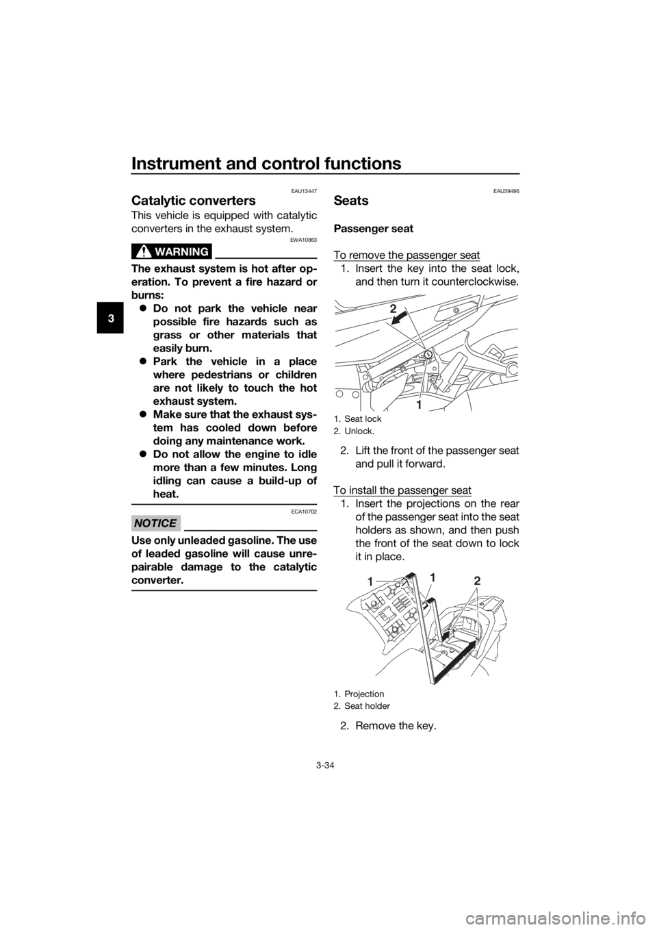
To remove the passenger seat
1. Insert the key into the seat lock, and then turn it counterclockwise.
2. Lift the front of the passenger seat and pull it forward.
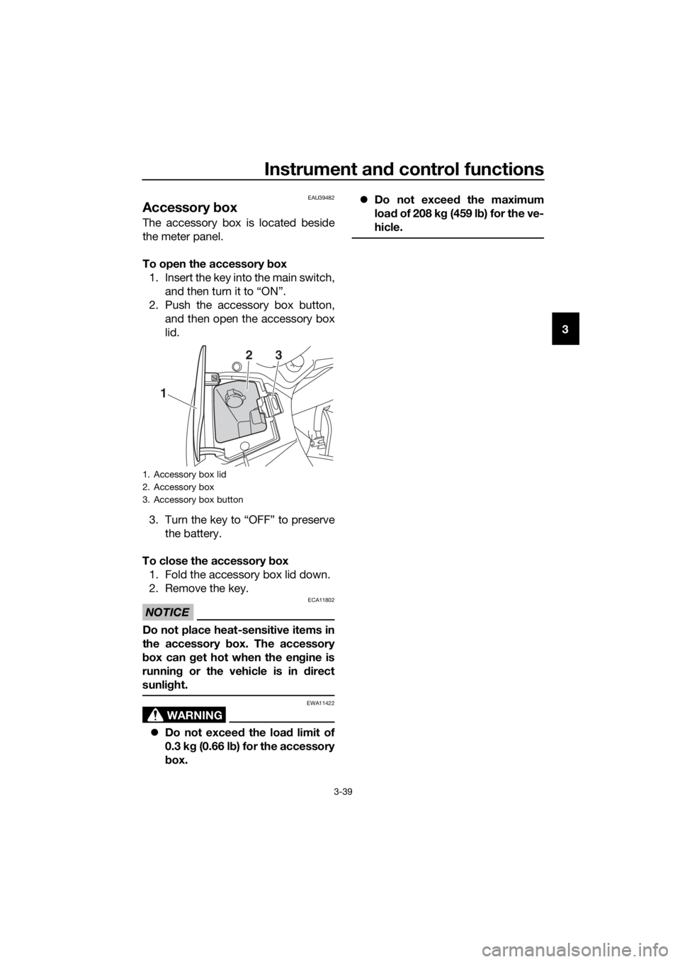
To install the passenger seat
1. Insert the projections on the rear of the passenger seat into the seat
holders as shown, and then push
the front of the seat down to lock
it in place.
2. Remove the key.
1. Seat lock
2. Unlock.
1. Projection
2. Seat holder
1
2
UB95E0E0.book Page 34 Friday, February 19, 2016 2:15 PM
Page 53 of 126

Instrument and control functions
3-39
3
EAU39482
Accessory box
The accessory box is located beside
the meter panel.
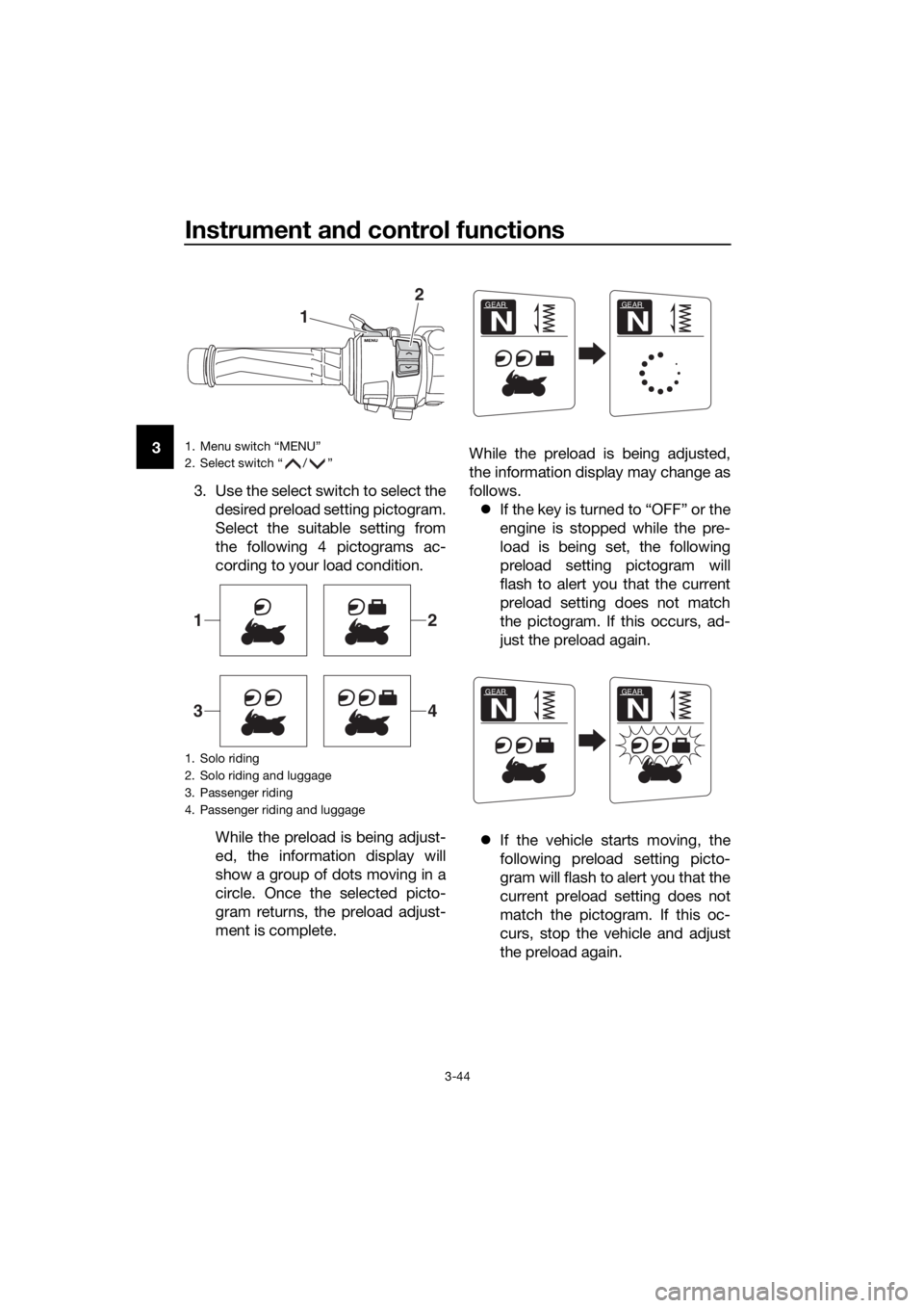
To open the accessory box
1. Insert the key into the main switch, and then turn it to “ON”.
2. Push the accessory box button, and then open the accessory box
lid.
3. Turn the key to “OFF” to preserve the battery.
To close the accessory box
1. Fold the accessory box lid down.
2. Remove the key.
NOTICE
ECA11802
Do not place heat-sensitive items in
the accessory box. The accessory
b ox can g et hot when the en gine is
runnin g or the vehicle is in direct
sunli ght.
WARNING
EWA11422
Do not exceed the load limit of
0.3 k g (0.66 l b) for the accessory
b ox.
Do not exceed the maximum
loa d of 208 k g (459 l b) for the ve-
hicle.
1. Accessory box lid
2. Accessory box
3. Accessory box button
1
23
UB95E0E0.book Page 39 Friday, February 19, 2016 2:15 PM
Page 57 of 126

Instrument and control functions
3-43
3
EAU55424
A djustin g the front an d rear
suspension
This model is equipped with an elec-
tronically adjustable suspension sys-
tem. The preload of the rear shock
absorber and the damping forces of
both the front fork and rear shock ab-
sorber can be adjusted.
WARNING
EWA12423
Be sure to stop the vehicle before
makin g any settin g chan ges to the
multi-function meter unit. Chang ing
settin gs while ri din g can d istract the
operator an d increase the risk of an
acci dent.
Preloa d
When riding with luggage or a passen-
ger, use the preload adjusting function
to adjust the suspension system to
match the load. There are 4 preload
settings.
TIP
The preload adjusting function will
appear only when the engine is
running.
Changing the preload setting will
also adjust the front and rear sus-
pension damping forces accord-
ingly. See “Damping force” on
page 3-45 for more information.
About cold temperature opera-
tion:
• When using the preload adjust- ing function, there should be no
weight on the vehicle.
• When using the preload adjust- ing function at ambient temper-
atures near or below 0 °C (32
°F), to protect the preload ad- justing function motor, the elec-
tronically adjustable suspension
system warning light may come
on.
• The suspension will still operate as normal, only the preload ad-
justing function cannot be used.
• To reset the electronically ad- justable suspension system
warning light, wait approximate-
ly 6 minutes and then turn the
key to “OFF” or immediately
turn the key to “OFF” and then
wait 6 minutes.
• If the electronically adjustable suspension system warning
light remains on, have a
Yamaha dealer check the sus- pension system.
To adjust the preload
1. Turn the key to “ON”, start the en- gine, and then shift the transmis-
sion into neutral.
2. Push the menu switch “MENU” to switch the function display to the
preload adjusting function.
1. Function display
2. Preload adjusting function
3. Preload setting pictogram
GEAR
N
1
3
2
UB95E0E0.book Page 43 Friday, February 19, 2016 2:15 PM
Page 58 of 126

Instrument and control functions
3-44
3
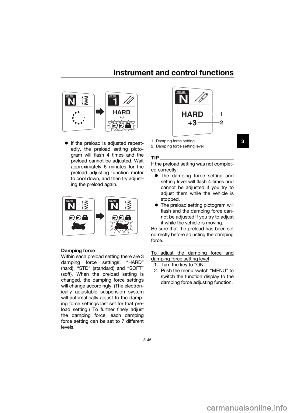
3. Use the select switch to select thedesired preload setting pictogram.
Select the suitable setting from
the following 4 pictograms ac-
cording to your load condition.
While the preload is being adjust-
ed, the information display will
show a group of dots moving in a
circle. Once the selected picto-
gram returns, the preload adjust-
ment is complete. While the preload is being adjusted,
the information display may change as
follows.
If the key is turned to “OFF” or the
engine is stopped while the pre-
load is being set, the following
preload setting pictogram will
flash to alert you that the current
preload setting does not match
the pictogram. If this occurs, ad-
just the preload again.
If the vehicle starts moving, the
following preload setting picto-
gram will flash to alert you that the
current preload setting does not
match the pictogram. If this oc-
curs, stop the vehicle and adjust
the preload again.1. Menu switch “MENU”
2. Select switch “ / ”
1. Solo riding
2. Solo riding and luggage
3. Passenger riding
4. Passenger riding and luggage
1
2
12
34
GEAR
N
GEAR
N
GEAR
N
GEAR
N
UB95E0E0.book Page 44 Friday, February 19, 2016 2:15 PM
Page 59 of 126

Instrument and control functions
3-45
3
If the preload is adjusted repeat-
edly, the preload setting picto-
gram will flash 4 times and the
preload cannot be adjusted. Wait
approximately 6 minutes for the
preload adjusting function motor
to cool down, and then try adjust-
ing the preload again.
Dampin g force
Within each preload setting there are 3
damping force settings: “HARD”
(hard), “STD” (standard) and “SOFT”
(soft). When the preload setting is
changed, the damping force settings
will change accordingly. (The electron-
ically adjustable suspension system
will automatically adjust to the damp-
ing force settings last set for that pre-
load setting.) To further finely adjust
the damping force, each damping
force setting can be set to 7 different
levels.
TIP
If the preload setting was not complet-
ed correctly: The damping force setting and
setting level will flash 4 times and
cannot be adjusted if you try to
adjust them while the vehicle is
stopped.
The preload setting pictogram will
flash and the damping force can-
not be adjusted if you try to adjust
it while the vehicle is moving.
Be sure that the preload has been set
correctly before adjusting the damping
force.
To adjust the damping force and
damping force setting level
1. Turn the key to “ON”.
2. Push the menu switch “MENU” to switch the function display to the
damping force adjusting function.
GEAR
1
HARD+3
GEAR
N
GEAR
N
GEAR
N
1. Damping force setting
2. Damping force setting level
GEAR
N
HARD+3
2
1
UB95E0E0.book Page 45 Friday, February 19, 2016 2:15 PM
Page 63 of 126

Instrument and control functions
3-49
3
With the engine turned off:
1. Place the vehicle on the centerstand.
2.
Move the sidestand down.
3. Make sure that the start/engine stop switch is set to “ ”.
4. Turn the key to “ON”.
5. Shift the transmission into the neutral position.
6. Keep the front or rear brake applied.
7.
Push the “ ” side of the start/engine
stop switch.
Does the engine start?
With the engine still running:
8. Move the sidestand up.
9. Shift the transmission into gear.
10. Move the sidestand down.
Does the engine stall?
After the engine has stalled:
11. Move the sidestand up.
12. Release the brake.
13.
Push the “ ” side of the
start/engine stop switch.
Does the engine start?
The system is OK. The motorcycle can
be ridden.
The neutral switch, a brake light switch
or the YCC-S system may not be
working correctly.
The motorcycle should not be ridden
until checked by a Yamaha dealer.
The sidestand switch may not be
working correctly.
The motorcycle should not be ridden
until checked by a Yamaha dealer.
A brake light switch may not be working
correctly.
The motorcycle should not be ridden
until checked by a Yamaha dealer.
WARNING
The vehicle must be placed on the centerstand during this inspection.
If a malfunction is noted, have a Yamaha dealer check the system
before riding.
TIP
The traction control system
indicator/warning light “TCS” may come
on, but this is not a malfunction.
YES NO
YESNO
NOYES
UB95E0E0.book Page 49 Friday, February 19, 2016 2:15 PM