2016 YAMAHA FJR1300AS instrument panel
[x] Cancel search: instrument panelPage 5 of 126

Table of contents
Safety information ............................1-1
Description ........................................2-1
Left view ..........................................2-1
Right view........................................2-2
Controls and instruments ................2-3
Instrument an d control functions ....3-1
Immobilizer system .........................3-1
Main switch/steering lock ...............3-2
Indicator lights and warning lights ............................................3-4
Cruise control system .....................3-8
Multi-function meter unit ...............3-11
D-mode (drive mode) ....................3-23
Handlebar switches.......................3-24
YCC-S system...............................3-26
Shift pedal .....................................3-26
Hand shift lever .............................3-27
Brake lever ....................................3-28
Brake pedal ...................................3-28
ABS ...............................................3-29
Traction control system.................3-30
Fuel tank cap.................................3-31
Fuel................................................3-32
Fuel tank overflow hose ................3-33
Catalytic converters .....................3-34
Seats .............................................3-34
Adjusting the rider seat height ......3-36
Storage compartment ...................3-38
Accessory box...............................3-39
Adjusting the headlight beams......3-40
Handlebar position ........................3-40
Opening and closing the cowling vents ..........................................3-41
Rear view mirrors ..........................3-42
Adjusting the front and rear suspension.................................3-43
Sidestand ......................................3-47
Ignition circuit cut-off system........3-48
Auxiliary DC jack ...........................3-50
Cornering lights .............................3-51 For your safety – pre-operation
checks
............................................... 4-1
Operation an d important ri din g
points ................................................. 5-1
Starting the engine.......................... 5-2
Shifting ............................................ 5-3
Tips for reducing fuel consumption................................ 5-5
Engine break-in ............................... 5-6
Parking ............................................ 5-7
Perio dic maintenance an d
a d justment ........................................ 6-1
Owner’s tool kit ............................... 6-2
Periodic maintenance chart for the emission control system.............. 6-3
General maintenance and lubrication chart........................... 6-4
Removing and installing panels ...... 6-7
Checking the spark plugs ............. 6-10
Canister......................................... 6-11
Engine oil and oil filter cartridge ... 6-11
Final gear oil.................................. 6-14
Coolant ......................................... 6-15
Air filter element ............................ 6-17
Checking the engine idling
speed......................................... 6-17
Checking the throttle grip free
play ............................................ 6-18
Valve clearance ............................. 6-18
Tires .............................................. 6-19
Cast wheels .................................. 6-21
YCC-S clutch ................................ 6-22
Checking the brake lever free play ............................................ 6-22
Brake light switches ...................... 6-23
Checking the front and rear brake pads........................................... 6-23
Checking the brake and YCC-S clutch fluid levels ....................... 6-24
Changing the brake and YCC-S clutch fluids ............................... 6-26
Checking and lubricating the cables ........................................ 6-26
UB95E0E0.book Page 1 Friday, February 19, 2016 2:15 PM
Page 32 of 126

Instrument and control functions
3-18
3 and return to the normal display, push
and hold the menu switch “MENU”
again for at least 2 seconds.
Adjusting the temperature levels of the
grip warmer settings
1. Use the select switch to highlight
“Grip Warmer”.
2. Push the “MENU” switch. The grip warmer setting display will be
shown and “High” will flash in the
display.
3. Push the “MENU” switch. The temperature level for the high set-
ting will start flashing.
Use the select switch to set the
temperature level, and then push
the “MENU” switch. “High” will
start flashing.
Display Description
This function allows you to
set the low, middle, and
high settings to 10 tem-
perature levels.
This function allows you to
check and reset the “OIL”
oil change interval (dis-
tance traveled), and the
“FREE-1” and “FREE-2”
maintenance intervals.
This function allows you to
check and reset the
“TIME–2” and “TIME–3”
functions. These time trips
show the total elapsed
time that the key has been
in the “ON” position. When
the key is turned to “OFF”,
the time trips stop count-
ing but are not reset. The
maximum time that can be
shown is 99:59.
When the time trips reach
99:59, they automatically
reset to 0:00 and continue
counting.
This function allows you to
switch the display units
between kilometers and
miles. When kilometers are
selected, the fuel con-
sumption units can be
switched between
“L/100km” and “km/L”.
This function allows you to
change the items shown in
3 information displays.
This function allows you to
adjust the brightness of
the multi-function meter
unit panel to suit the out-
side lighting conditions.
This function allows you to
set the clock.
This function allows you to
reset all items, except the
odometer and the clock.
Grip Warmer
Maintenance
Time Trip
Unit
Display
Brightness
Clock
All Reset
MENU
Grip Warmer
Maintenance
Time Trip
Unit
Display
Brightness
Clock
Grip Warmer
Hi g
h
10
Middle
5
Low
1
UB95E0E0.book Page 18 Friday, February 19, 2016 2:15 PM
Page 36 of 126

Instrument and control functions
3-22
3 Adjusting the meter panel brightness
1. Use the select switch to highlight
“Brightness”.
2. Push the “MENU” switch.
3. Use the select switch to select the desired brightness level, and then
push the “MENU” switch to return
to the setting mode menu.
Setting the clock
1. Use the select switch to highlight “Clock”.
2. Push the “MENU” switch. 3. When the hour digits start flash-
ing, use the select switch to set
the hours.
4. Push the “MENU” switch, and the minute digits start flashing.
5. Use the select switch to set the minutes.
6. Push the “MENU” switch to return to the setting mode menu.
Resetting all of the display items
1. Use the select switch to highlight “All Reset”.
2. Push the “MENU” switch.
3. Use the select switch to highlight “YES”, and then push the “MENU”
switch.
MENU
Grip Warmer
Maintenance
Time Trip
Unit
Display
Brightness
Clock
Brightness
MENU
Grip Warmer
Maintenance
Time Trip
Unit
Display
Brightness
Clock
Clock
555
MENU
Maintenance
Time Trip
Unit
Display
Brightness
Clock
All Reset
UB95E0E0.book Page 22 Friday, February 19, 2016 2:15 PM
Page 53 of 126

Instrument and control functions
3-39
3
EAU39482
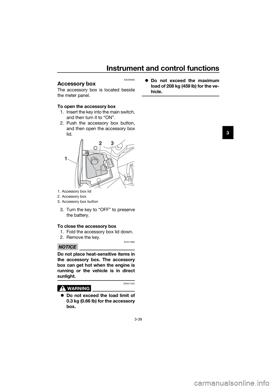
Accessory box
The accessory box is located beside
the meter panel.
To open the accessory box
1. Insert the key into the main switch, and then turn it to “ON”.
2. Push the accessory box button, and then open the accessory box
lid.
3. Turn the key to “OFF” to preserve the battery.
To close the accessory box
1. Fold the accessory box lid down.
2. Remove the key.
NOTICE
ECA11802
Do not place heat-sensitive items in
the accessory box. The accessory
b ox can g et hot when the en gine is
runnin g or the vehicle is in direct
sunli ght.
WARNING
EWA11422
Do not exceed the load limit of
0.3 k g (0.66 l b) for the accessory
b ox.
Do not exceed the maximum
loa d of 208 k g (459 l b) for the ve-
hicle.
1. Accessory box lid
2. Accessory box
3. Accessory box button
1
23
UB95E0E0.book Page 39 Friday, February 19, 2016 2:15 PM
Page 55 of 126

Instrument and control functions
3-41
3
EAU54151
Openin g an d closin g the cowl-
in g vents
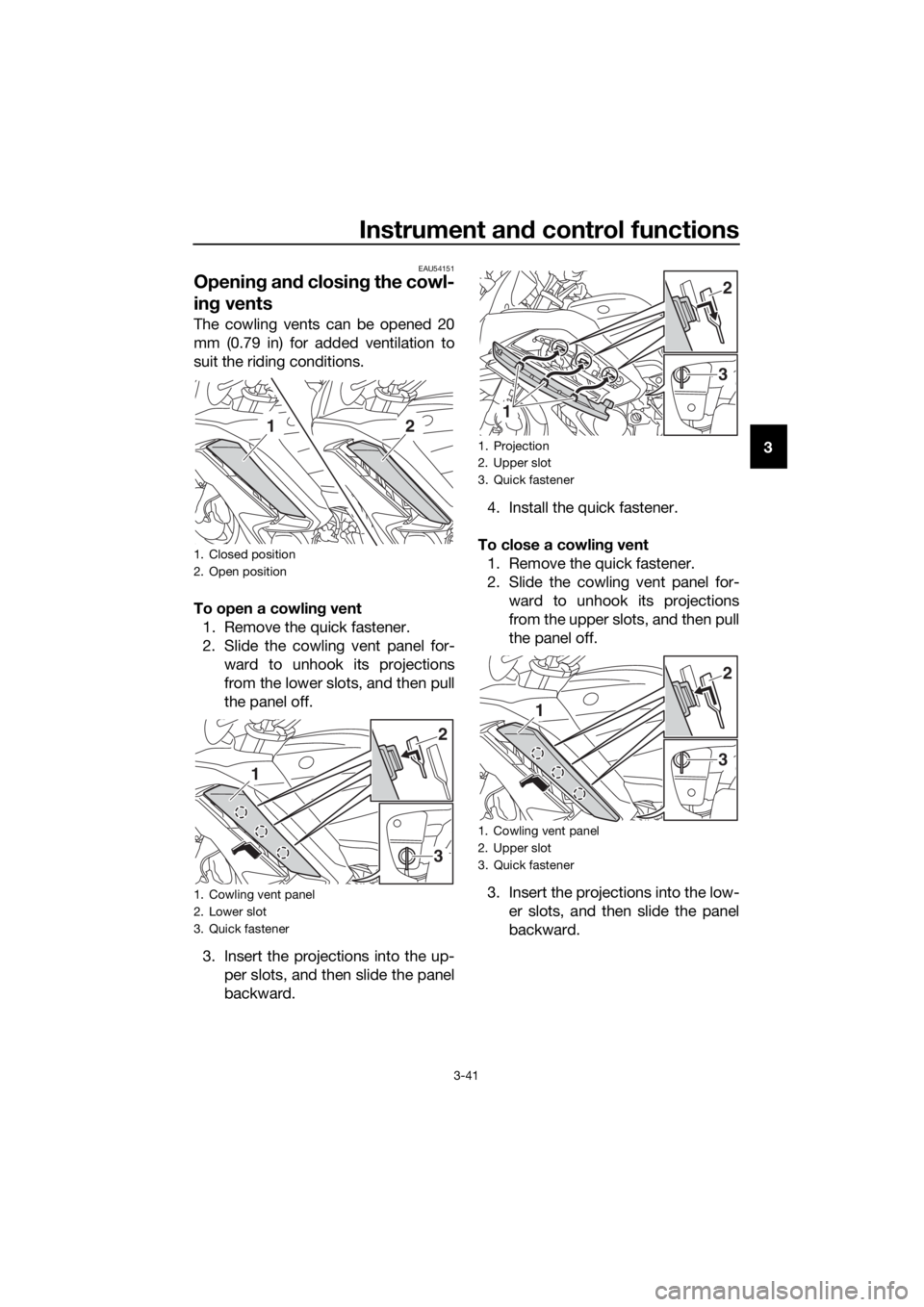
The cowling vents can be opened 20
mm (0.79 in) for added ventilation to
suit the riding conditions.
To open a cowlin g vent
1. Remove the quick fastener.
2. Slide the cowling vent panel for- ward to unhook its projections
from the lower slots, and then pull
the panel off.
3. Insert the projections into the up- per slots, and then slide the panel
backward. 4. Install the quick fastener.
To close a cowlin g vent
1. Remove the quick fastener.
2. Slide the cowling vent panel for- ward to unhook its projections
from the upper slots, and then pull
the panel off.
3. Insert the projections into the low- er slots, and then slide the panel
backward.
1. Closed position
2. Open position
1. Cowling vent panel
2. Lower slot
3. Quick fastener
12
3
1
2
1. Projection
2. Upper slot
3. Quick fastener
1. Cowling vent panel
2. Upper slot
3. Quick fastener
1
3
2
3
1
2
UB95E0E0.book Page 41 Friday, February 19, 2016 2:15 PM
Page 56 of 126

Instrument and control functions
3-42
3
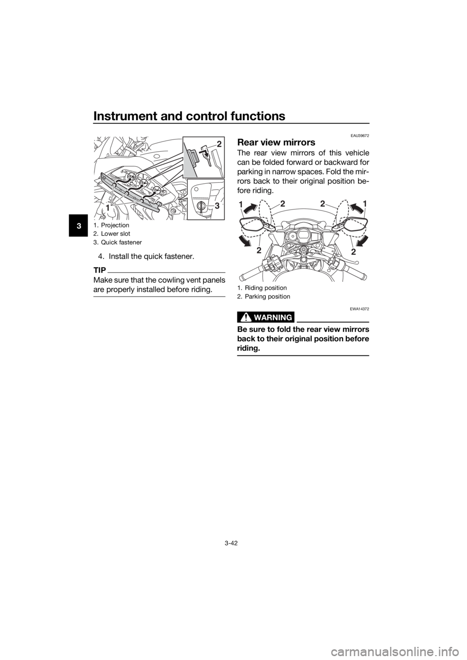
4. Install the quick fastener.
TIP
Make sure that the cowling vent panels
are properly installed before riding.
EAU39672
Rear view mirrors
The rear view mirrors of this vehicle
can be folded forward or backward for
parking in narrow spaces. Fold the mir-
rors back to their original position be-
fore riding.
WARNING
EWA14372
Be sure to fol d the rear view mirrors
b ack to their ori ginal position before
ri din g.
1. Projection
2. Lower slot
3. Quick fastener
13
2
1. Riding position
2. Parking position
2
2
1
2 2
1
UB95E0E0.book Page 42 Friday, February 19, 2016 2:15 PM
Page 113 of 126

Motorcycle care and stora ge
7-2
7
structed
. Also, thorou ghly rinse
the area off with water, immed i-
ately dry it, an d then apply a cor-
rosion protection spray.
Improper cleanin g can damag e
plastic parts (such as cowlin gs,
panels, win dshield s, head light
lenses, meter lenses, etc.) an d
the mufflers. Use only a soft,
clean cloth or spon ge with wa-
ter to clean plastic. However, if
the plastic parts cannot be thor-
ou ghly cleaned with water, di-
lute d mil d d eter gent with water
may be used . Be sure to rinse
off any d etergent resi due usin g
plenty of water, as it is harmful
to plastic parts.
Do not use any harsh chemical
prod ucts on plastic parts. Be
sure to avoi d usin g cloths or
spon ges which have b een in
contact with stron g or a brasive
cleanin g prod ucts, solvent or
thinner, fuel ( gasoline), rust re-
movers or inhi bitors,
b rake flui d,
antifreeze or electrolyte.
Do not use hi gh-pressure wash-
ers or steam-jet cleaners since
they cause water seepag e and
d eterioration in the followin g ar-
eas: seals (of wheel an d swin g-
arm bearin gs, fork an d b rakes),
electric components (couplers,
connectors, instruments,
switches an d li ghts), breather
hoses an d vents.
For motorcycles equippe d with
a win dshiel d: Do not use stron g
cleaners or har d spon ges as
they will cause dullin g or
scratching . Some cleanin gcompoun
ds for plastic may
leave scratches on the wind -
shiel d. Test the prod uct on a
small hidden part of the win d-
shiel d to make sure that it does
not leave any marks. If the win d-
shiel d is scratche d, use a quality
plastic polishin g compoun d af-
te r
washin g.
After normal use
Remove dirt with warm water, a mild
detergent, and a soft, clean sponge,
and then rinse thoroughly with clean
water. Use a toothbrush or bottlebrush
for hard-to-reach areas. Stubborn dirt
and insects will come off more easily if
the area is covered with a wet cloth for
a few minutes before cleaning.
After riding in the rain, near the sea or
on salt-sprayed roads
Since sea salt or salt sprayed on roads
during winter are extremely corrosive
in combination with water, carry out
the following steps after each ride in
the rain, near the sea or on salt-
sprayed roads.
TIP
Salt sprayed on roads in the winter
may remain well into spring.
1. Clean the motorcycle with cold
water and a mild detergent, after
the engine has cooled down.
NOTICE: Do not use warm wa-
ter since it increases the corro-
sive action of the salt.
[ECA10792]
UB95E0E0.book Page 2 Friday, February 19, 2016 2:15 PM