2016 VOLVO V60 CROSS COUNTRY ECU
[x] Cancel search: ECUPage 145 of 402
05 Loading and storage
05
}}
143
Cargo area cover
The cargo area cover can be used to conceal objects in the cargo area.
Use
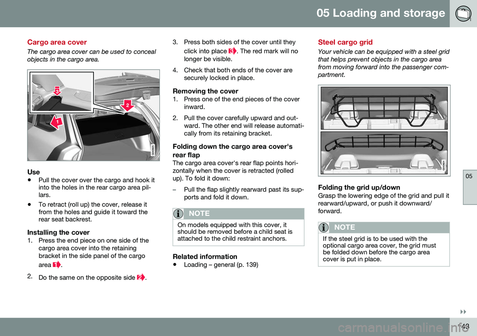
•Pull the cover over the cargo and hook it into the holes in the rear cargo area pil-lars.
• To retract (roll up) the cover, release itfrom the holes and guide it toward therear seat backrest.
Installing the cover1. Press the end piece on one side of the
cargo area cover into the retaining bracket in the side panel of the cargo area
.
2. Do the same on the opposite side
. 3. Press both sides of the cover until they
click into place
. The red mark will no
longer be visible.
4. Check that both ends of the cover are securely locked in place.
Removing the cover1. Press one of the end pieces of the coverinward.
2. Pull the cover carefully upward and out- ward. The other end will release automati- cally from its retaining bracket.
Folding down the cargo area cover's rear flap
The cargo area cover's rear flap points hori- zontally when the cover is retracted (rolledup). To fold it down:
–Pull the flap slightly rearward past its sup- ports and fold it down.
NOTE
On models equipped with this cover, it should be removed before a child seat isattached to the child restraint anchors.
Related information
• Loading – general (p. 139)
Steel cargo grid
Your vehicle can be equipped with a steel grid that helps prevent objects in the cargo areafrom moving forward into the passenger com-partment.
Folding the grid up/downGrasp the lowering edge of the grid and pull it rearward/upward, or push it downward/forward.
NOTE
If the steel grid is to be used with the optional cargo area cover, the grid mustbe folded down before the cargo areacover is put in place.
Page 190 of 402

07 Driver support
07
188
Radar sensor
The radar sensor is designed to help detect cars or larger vehicles driving in the samedirection as your vehicle, in the same lane.
The radar sensor and its limitationsIn addition to being used by the AdaptiveCruise Control (ACC), the radar sensor is alsoused by Distance Alert (see Distance Alert –introduction (p. 193)) and Collision Warningwith Full Auto-brake and Pedestrian Detec-tion (see Collision warning – introduction(p. 204)).
WARNING
•If there is visible damage to the front grille or you suspect that the radarsensor may be damaged in any way,contact a trained and qualified Volvoservice technician as soon as possible.The radar sensor may only functionpartially (or not at all) if it is damagedor is not securely fastened in place.
• Accessories or other objects, such asextra headlights, must not be installedin front of the grille.
• Modification of the radar sensor couldmake its use illegal.
The radar sensor's capacity to detect vehi- cles ahead is impeded:
• if the radar sensor is obstructed and can- not detect other vehicles, for example in heavy rain, or if snow or other objects areobscuring the radar sensor.
NOTE
Keep the area in front of the radar sensor clean.
•
if the speed of vehicles ahead is signifi- cantly different from your own speed.
Related information
•Adaptive Cruise Control – introduction(p. 179)
• Collision warning – introduction (p. 204)
• Distance Alert – introduction (p. 193)
Adaptive Cruise Control – limitations
The ACC cannot cover all driving situations and traffic, weather and road conditions.
Situations where ACC may not function optimally
WARNING
• The radar sensor has a limited field of vision. In some situations it may detecta vehicle later than expected or notdetect other vehicles at all.
• If ACC is not functioning properly,cruise control will also be disabled.
Page 241 of 402

07 Driver support
07
}}
* Option/accessory, for more information, see Introduction.239
Park Assist Pilot (PAP)* – limitations
The PAP parking procedure will be cancelled if.
• The vehicle's speed goes above approxi- mately 4 mph 7 km/h
• The driver moves the steering wheel
• If the stability or ABS systems are acti-vated (e.g., if a wheel starts to spinbecause of a slippery road surface
If the system has been switched off, this will be indicated by a text message in the instru-ment panel.
NOTE
• PAP will not function correctly if its sensors are obstructed by dirt, snow,etc.
• In certain situations, PAP may not beable to measure a parking space. Thiscould be due to external sources ofsound (e.g., a vehicle's horn, tires onwet asphalt, pneumatic brakes, noisefrom a motorcycle's exhaust, etc.)emitting ultrasound using approxi-mately the same frequencies as PAP.
Information to keep in mindPAP is only intended to provide parallel park- ing assistance but may not be able to func-tion fully in all situations. •
PAP's function is based on the way that the vehicles are parked behind and infront of your parking space. If they are,for example, parked too close to the curb,there is a risk that your vehicle's tires orwheel rims could be damaged by thecurb during the parking procedure.
• PAP is intended to provide parking assis-tance on straight streets, not sections ofstreet with curved or irregular curbs. Besure that your vehicle is parallel to thecurb when PAP measures the parkingspace.
• PAP may not be able to provide parkingassistance on narrow streets due to lackof space to maneuver the vehicle. In sit-uations like this, it may help to drive asclose to the side of the road as possiblewhere the parking space is located.
• Use only approved tires with the correctinflation pressure because this affectsPAP's capacity to provide parking assis-tance. See the table in Tire inflation –pressure table (p. 305). Changing to adifferent approved tire size may affectPAP's parameters. Consult a trained andqualified Volvo service technician.
• Heavy rain or snow may inhibit PAP'scapacity to correctly measure a parkingspace.
• Do not use PAP if snow chains or a tem-porary spare tire is being used.
• Do not use PAP if there are any objectsprotruding from the vehicle.
WARNING
• The front end of your vehicle may turn out toward oncoming traffic during theparking procedure.
• Objects located above the parkingsensors' field of vision are not includedwhen PAP measures a parking space.For this reason, PAP may turn into theparking space too soon. Avoid parkingspaces of this type.
• The driver is always responsible fordetermining if PAP has selected a suit-able parking space.
Maintenance
Generic illustration. The PAP sensors are located in the front and rear bumpers
PAP uses the same sensors as the Park assist system, see Park assist – limitations(p. 235)).
Page 252 of 402
07 Driver support
07
250* Option/accessory, for more information, see Introduction.
BLIS* – messages
If BLIS/CTA 18
are not functioning normally, a
symbol will illuminate in the instrument panel and a text message will be displayed. Followany instructions that may be provided. These messages include:
MessageSystem status
CTA OFFCTA has been switched off manually. BLIS remainsactive.
BLIS and CTA OFFTrailerattachedBLIS and CTA are tempo- rarily deactivated becausea trailer's wiring has beenconnected to the vehicle'selectrical system.
BLIS and CTA Serv-ice requiredBLIS and CTA are not functioning normally.
• If this message recurs, the systems should beinspected by a trainedand qualified Volvoservice technician.
Messages can be erased by pressing the
OK
button on the left steering wheel lever.
Related information
• BLIS* – introduction (p. 245)
• BLIS* – function (p. 246)
• BLIS* – operation (p. 247)
• BLIS* – Cross Traffic Alert (CTA) (p. 247)
• BLIS* – limitations (p. 249)
18
Cross Traffic Alert
Page 254 of 402

08 Starting and driving
08
252* Option/accessory, for more information, see Introduction.
Starting the engine
The engine can be started/switched off using the remote key and the START/STOP
ENGINE button.
Ignition slot with remote key inserted (see Igni- tion modes (p. 77) for more information on igni-tion modes)
WARNING
Before starting the engine:
• Fasten the seat belt.
• Check that the seat, steering wheel and mirrors are adjusted properly.
• Make sure the brake pedal can bedepressed completely. Adjust the seatif necessary.
WARNING
•Never use more than one floor mat at a time on the driver's floor. Beforedriving, remove the original mat fromthe driver's seat floor before using anyother type of floor mat. Any mat usedin this position should be securely andproperly anchored in the attachingpins. An extra mat on the driver's floorcan cause the accelerator and/orbrake pedal to catch. Check that themovement of these pedals is not impe-ded.
• Volvo's floor mats are specially manu-factured for your car. They must befirmly secured in the clips on the floorso that they cannot slide and becometrapped under the pedals on the driv-er's side.
1. Press the remote key into the ignition slot
as far as possible, with the metallic key blade pointing outward (not inserted into the slot) 1
.
2. Depress the brake pedal 2
. 3. Press and release the
START/STOP
ENGINE button. The autostart function
will operate the starter motor until the engine starts or until its overheating func-tion stops it. The starter motor operates for a maxi- mum of 10 seconds. If the engine has notstarted, repeat the procedure.
CAUTION
If the engine does not start after the third try, wait for approximately 3 minutesbefore trying to start it again to give thebattery time to recover its startingcapacity.
NOTE
Keyless drive *
To start a vehicle equipped with the key- less drive feature, one of the remote keysmust be in the passenger compartment.Follow the instructions in steps 2 and 3 tostart the vehicle.
1 On vehicles with the optional keyless drive, it is only necessary to have a remote key in the passenger’s compartment.
2 If the vehicle is moving, it is only necessary to press the START/STOP ENGINE button to start the vehicle.
Page 261 of 402
08 Starting and driving
08
}}
* Option/accessory, for more information, see Introduction.259
Transmission – Geartronic
Geartronic allows you to manually shift among your vehicle's forward gears. The manualposition ( +S–) can be selected at any time.
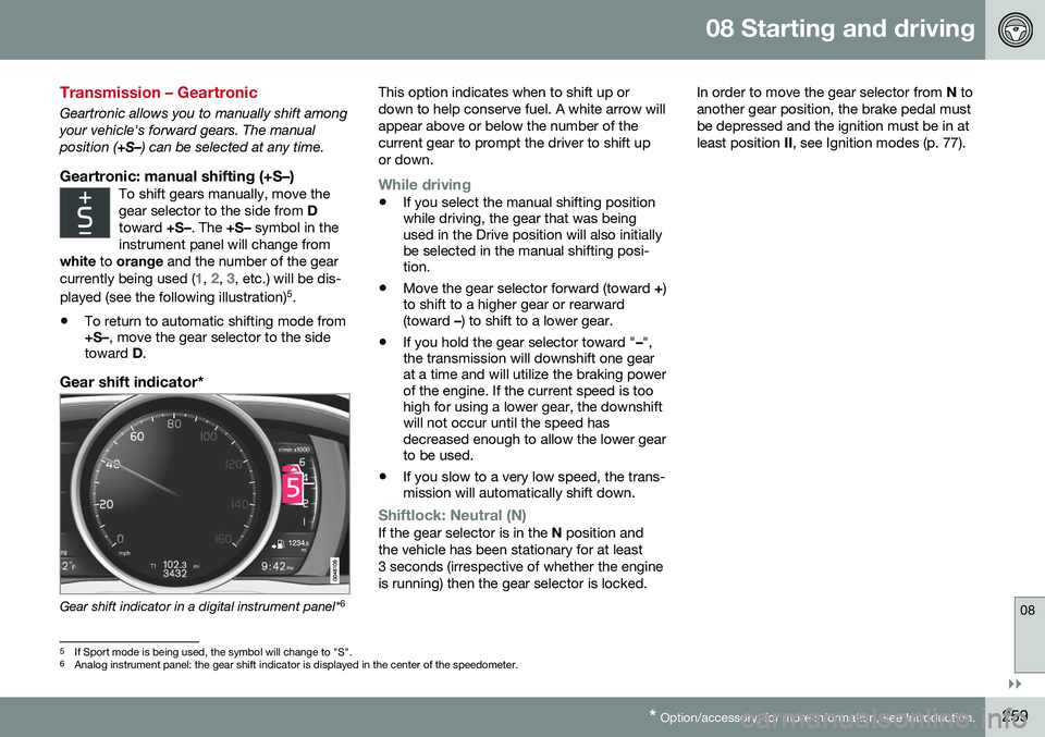
Geartronic: manual shifting (+S–)To shift gears manually, move thegear selector to the side from D
toward +S–. The +S– symbol in the
instrument panel will change from
white to orange and the number of the gear
currently being used (
1, 2, 3, etc.) will be dis-
played (see the following illustration) 5
.
• To return to automatic shifting mode from +S–
, move the gear selector to the side
toward D.
Gear shift indicator*
Gear shift indicator in a digital instrument panel* 6This option indicates when to shift up or down to help conserve fuel. A white arrow willappear above or below the number of thecurrent gear to prompt the driver to shift upor down.
While driving
•
If you select the manual shifting position while driving, the gear that was beingused in the Drive position will also initiallybe selected in the manual shifting posi-tion.
• Move the gear selector forward (toward
+)
to shift to a higher gear or rearward(toward –) to shift to a lower gear.
• If you hold the gear selector toward "
–",
the transmission will downshift one gearat a time and will utilize the braking powerof the engine. If the current speed is toohigh for using a lower gear, the downshiftwill not occur until the speed hasdecreased enough to allow the lower gearto be used.
• If you slow to a very low speed, the trans-mission will automatically shift down.
Shiftlock: Neutral (N)If the gear selector is in the
N position and
the vehicle has been stationary for at least 3 seconds (irrespective of whether the engineis running) then the gear selector is locked. In order to move the gear selector from
N to
another gear position, the brake pedal mustbe depressed and the ignition must be in atleast position II, see Ignition modes (p. 77).
5
If Sport mode is being used, the symbol will change to "S".
6 Analog instrument panel: the gear shift indicator is displayed in the center of the speedometer.
Page 277 of 402
08 Starting and driving
08
275
Connect an auxiliary battery if the battery voltage is too low, see Jump starting (p. 256).
Parking on a hill
•
If the vehicle is pointing uphill, turn the front wheels so that they point away fromthe curb.
• If the vehicle is pointing downhill, turn thefront wheels so that they point toward thecurb.
The parking brake should also be applied.
Related information
• Parking brake – applying (p. 275)
• Parking brake – releasing (p. 276)
• Parking brake – symbols and messages(p. 277)
• Brakes – general (p. 271)
Parking brake – applying
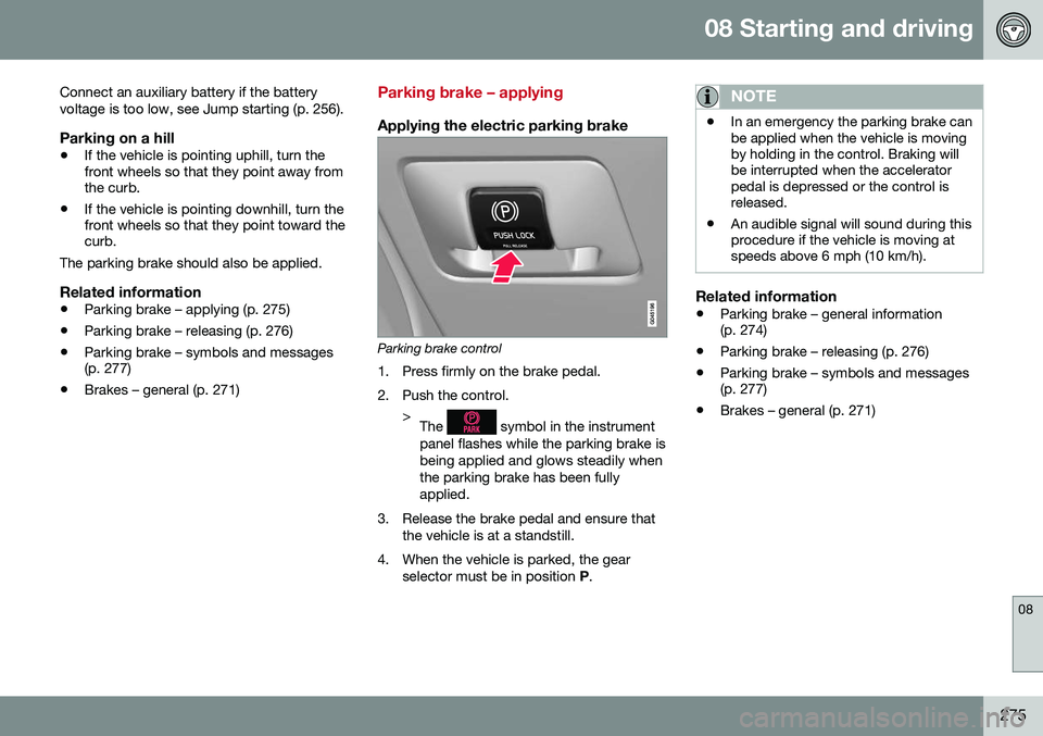
Applying the electric parking brake
Parking brake control
1. Press firmly on the brake pedal.
2. Push the control. >The
symbol in the instrument
panel flashes while the parking brake is being applied and glows steadily whenthe parking brake has been fullyapplied.
3. Release the brake pedal and ensure that the vehicle is at a standstill.
4. When the vehicle is parked, the gear selector must be in position P.
NOTE
• In an emergency the parking brake can be applied when the vehicle is movingby holding in the control. Braking willbe interrupted when the acceleratorpedal is depressed or the control isreleased.
• An audible signal will sound during thisprocedure if the vehicle is moving atspeeds above 6 mph (10 km/h).
Related information
•
Parking brake – general information (p. 274)
• Parking brake – releasing (p. 276)
• Parking brake – symbols and messages(p. 277)
• Brakes – general (p. 271)
Page 292 of 402
||
08 Starting and driving
08
290
CAUTION
General towing precautions:• Please check with state and local authorities before attempting this typeof towing, as vehicles being towed aresubject to regulations regarding maxi-mum towing speed, length and type oftowing device, lighting, etc.
• If the vehicle's battery is dead, seeJump starting (p. 256) to provide cur-rent for releasing the electric parkingbrake and to move the gear selectorfrom the
P position to N. If this is not
possible, see Transmission – shiftlockoverride (p. 261) for information aboutmanually overriding the shiftlock sys-tem to move the gear selector from P
to N.
• Maximum speed: 50 mph (80 km/h).Do not exceed the maximum allowabletowing speed.
• Maximum distance with front wheelson ground: 50 miles (80 km).
• The vehicle should only be towed inthe forward direction.
Related information
•
Towing eyelet (p. 290)
• Remote key – functions (p. 149)
Towing eyelet
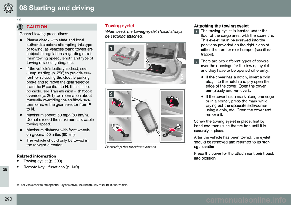
When used, the towing eyelet should always be securing attached.
Removing the front/rear covers
Attaching the towing eyeletThe towing eyelet is located under the floor of the cargo area, with the spare tire.This eyelet must be screwed into thepositions provided on the right sides ofeither the front or rear bumper (see illus-tration).
There are two different types of covers over the openings for the towing eyeletand they have to be opened differently.
• If the cover has a notch, insert a coin, etc., into the notch and pry open theedge of the cover. Open the covercompletely and remove it.
• If the cover has a mark along one edgeor in a corner, press the mark whileprying out the opposite side/cornerusing a coin, etc. Open the cover andremove it.
Screw the towing eyelet in place, first by hand and then using the tire iron until it issecurely in place. After the vehicle has been towed, the eyelet should be removed and returned to its stor-age location. Press the cover for the attachment point back into position.
21 For vehicles with the optional keyless drive, the remote key must be in the vehicle.