2016 VOLVO V60 CROSS COUNTRY ECU
[x] Cancel search: ECUPage 301 of 402
09 Wheels and tires
09
* Option/accessory, for more information, see Introduction.299
Changing a wheel – spare wheel
Wheel changes should always be carried out correctly.
Spare tireA spare tire can be purchased for your vehi-cle as an accessory. Follow the instructionsincluded with the spare tire regarding use andstowing in the vehicle. See also Changing awheel – removing wheel (p. 296) for additionalinformation.
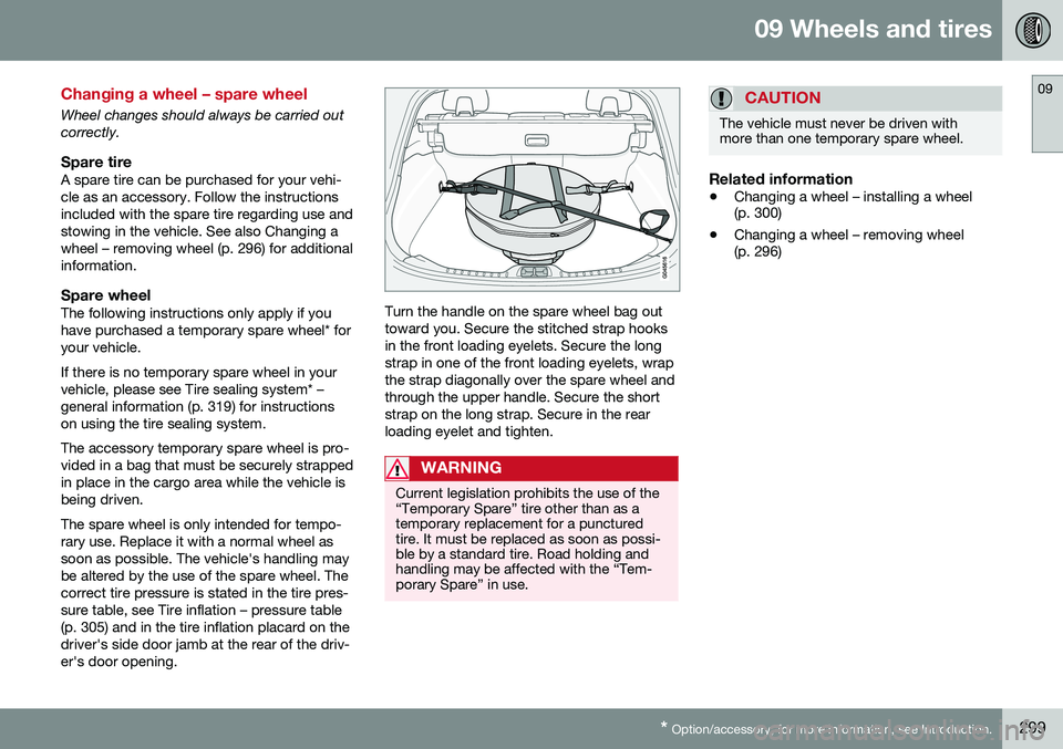
Spare wheelThe following instructions only apply if youhave purchased a temporary spare wheel* foryour vehicle. If there is no temporary spare wheel in your vehicle, please see Tire sealing system* –general information (p. 319) for instructionson using the tire sealing system. The accessory temporary spare wheel is pro- vided in a bag that must be securely strappedin place in the cargo area while the vehicle isbeing driven. The spare wheel is only intended for tempo- rary use. Replace it with a normal wheel assoon as possible. The vehicle's handling maybe altered by the use of the spare wheel. Thecorrect tire pressure is stated in the tire pres-sure table, see Tire inflation – pressure table(p. 305) and in the tire inflation placard on thedriver's side door jamb at the rear of the driv-er's door opening.Turn the handle on the spare wheel bag out toward you. Secure the stitched strap hooksin the front loading eyelets. Secure the long strap in one of the front loading eyelets, wrapthe strap diagonally over the spare wheel andthrough the upper handle. Secure the shortstrap on the long strap. Secure in the rearloading eyelet and tighten.
WARNING
Current legislation prohibits the use of the “Temporary Spare” tire other than as atemporary replacement for a puncturedtire. It must be replaced as soon as possi-ble by a standard tire. Road holding andhandling may be affected with the “Tem-porary Spare” in use.
CAUTION
The vehicle must never be driven with more than one temporary spare wheel.
Related information
• Changing a wheel – installing a wheel (p. 300)
• Changing a wheel – removing wheel(p. 296)
Page 302 of 402
09 Wheels and tires
09
300* Option/accessory, for more information, see Introduction.
Changing a wheel – accessing the spare wheel
The following procedure explains how to access the spare wheel (where applicable).
1. Release the bag's retaining straps.
2. Lift the bag out of the vehicle and remove
the spare wheel from the bag.
3. Fold up the floor hatch in the cargo area.
4. Remove the jack* and tools* from the foam block and change the wheels (see the instructions in the following section"Changing a wheel").
5. After changing wheels, return the jack and tools to the foam block and close thefloor hatch.
6. If possible, place the wheel with the punctured tire in the bag. 7. If there is a wheel in the bag, strap the
bag securely in place in the cargo area.WARNING
•If there is a wheel in the bag, the bag must be securely restrained using itsstraps and the load anchoring eyelets inthe cargo area. See (p. 299) and care-fully follow the instructions.
• If the wheel with the punctured tire istoo big to fit in the bag, it should besecurely restrained in the cargo areausing suitable straps, a net for anchor-ing cargo, etc.
Changing a wheel – installing a wheel
It is important to re-install wheels properly.
Re-installing the wheel1. Clean the contact surfaces on the wheel
and hub.
2. Lift the wheel and place it on the hub.
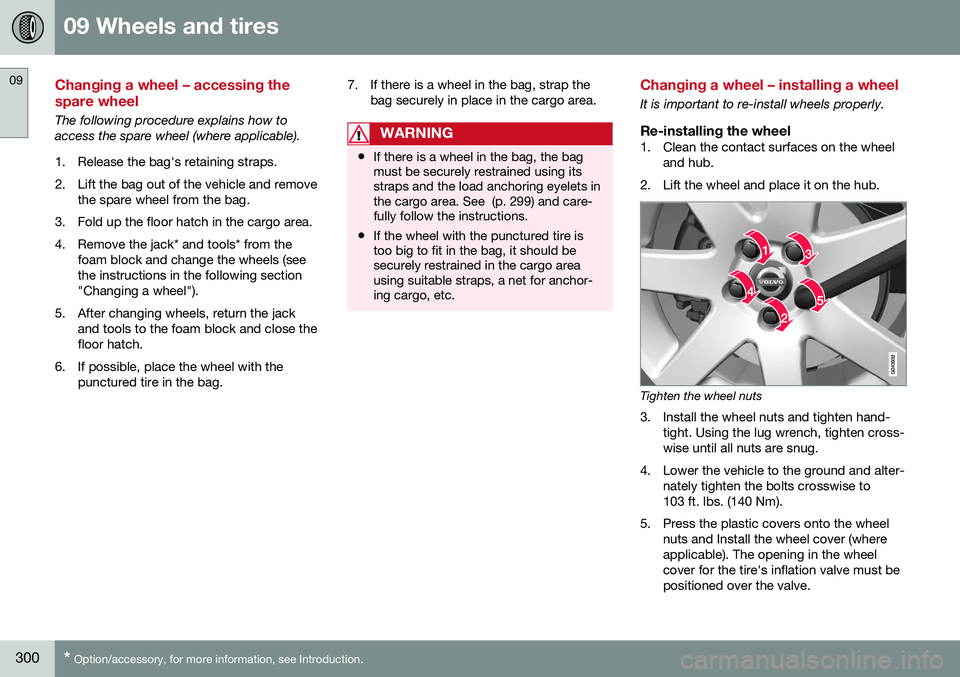
Tighten the wheel nuts
3. Install the wheel nuts and tighten hand- tight. Using the lug wrench, tighten cross- wise until all nuts are snug.
4. Lower the vehicle to the ground and alter- nately tighten the bolts crosswise to103 ft. lbs. (140 Nm).
5. Press the plastic covers onto the wheel nuts and Install the wheel cover (whereapplicable). The opening in the wheelcover for the tire's inflation valve must bepositioned over the valve.
Page 324 of 402
||
09 Wheels and tires
09
322
WARNING
The bottle is equipped with a catch to keep it securely in place and help preventsealing compound leakage. Once in place,the bottle cannot be unscrewed. This mustbe done by a trained and qualified Volvoservice technician.
5. Remove the valve cap from the tire’sinflation valve and screw the tire sealing system’s hose connector onto the valveas tightly as possible by hand.
6. Connect the electrical wire to the nearest 12-volt socket in the vehicle.
NOTE
Be sure that none of the other 12-volt sockets is being used while the compres-sor is in operation.
7. Start the vehicle’s engine.
WARNING
The vehicle´s engine should be running when the tire sealing system is used toavoid battery drain. Therefore, be sure thevehicle is parked in a well ventilated place,or outdoors, before using the system.
8. Start the tire sealing system’s compres-sor by pressing the on/off switch to posi- tion I.
WARNING
• Never stand next to the tire being infla- ted when the compressor is in opera-tion.
• If cracks, bubbles, etc. form on the tire,switch off the compressor immediately.
• If there is visible damage to the sidewallor the rim, the tire cannot be repaired.The vehicle should not be driven if thisoccurs. Contact a towing service orVolvo On Call Roadside Assistance ifapplicable.
NOTE
The air pressure gauge will temporarily show an increase in pressure to approxi-mately 88 psi (6 bar) while the sealingcompound is being pumped into the tire.The pressure should return to a normallevel after approximately 30 seconds.
9. Within seven minutes, inflate the tire to
between 22—44 psi (1.8—3.0 bar). Switch off the compressor briefly to get aclear reading from the pressure gauge.
Page 326 of 402

09 Wheels and tires
09
324* Option/accessory, for more information, see Introduction.
Tire sealing system* – inflating tires
The tire sealing system can be used to inflate the tires. To do so:
1. Park the car in a safe place.
2. The compressor should be switched off.
Ensure that the on/off switch is in position0 (the 0 side of the switch should be
pressed down).
3. Take out the electrical wire and hose.
4. Remove the valve cap from the tire’s inflation valve and screw the hose con- nector onto the valve as tightly as possi-ble by hand.
5. Connect the electrical wire to the nearest 12-volt socket in the vehicle.
6. Start the vehicle’s engine.WARNING
• The vehicle’s engine should be running when the tire sealing system is used toavoid battery drain. Therefore, be surethe vehicle is parked in a well ventilatedplace, or outdoors, before using thesystem. The parking brake should besecurely applied and the gear selectorshould be in the
P (park) position.
• Children should never be left unatten-ded in the vehicle when the engine isrunning.
7. Check the tire’s inflation pressure on the
gauge. Switch off the compressor briefly to get a clear reading from the pressuregauge.
8. Refer to the tire inflation table in this chapter for the correct inflation pressure.If the tire needs to be inflated, start thetire sealing system’s compressor (pressthe on/off switch to position I). If neces-sary, release air from the tire by turningthe air release knob counterclockwise.
CAUTION
The compressor should not be used for more than 10 minutes at a time to avoidoverheating.
9. Turn off the compressor (press the on/off switch to position 0) when the correct
inflation pressure has been reached.
10. Unscrew the hose from the tire’s inflation valve and reinstall the valve cap.
CAUTION
•After inflating the tires, always reinstall the valve cap to help avoid damage tothe valve from dirt, gravel, etc.
• Use plastic valve caps only. Metal capscould corrode and become difficult toremove.
11. Disconnect the electrical wire from the
12-volt socket.
Page 344 of 402
||
10 Maintenance and servicing
10
342
Related information
•Bulbs – headlight housing (p. 340)
• Bulbs – low beam, Halogen (p. 342)
• Bulbs – high beam, Halogen (p. 342)
• Bulbs – extra high beam (p. 343)
Bulbs – low beam, Halogen
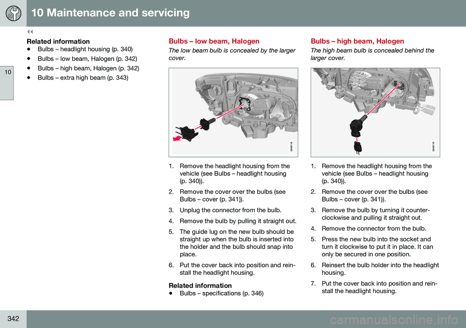
The low beam bulb is concealed by the larger cover.
1. Remove the headlight housing from the
vehicle (see Bulbs – headlight housing (p. 340)).
2. Remove the cover over the bulbs (see Bulbs – cover (p. 341)).
3. Unplug the connector from the bulb.
4. Remove the bulb by pulling it straight out.
5. The guide lug on the new bulb should be straight up when the bulb is inserted into the holder and the bulb should snap intoplace.
6. Put the cover back into position and rein- stall the headlight housing.
Related information
• Bulbs – specifications (p. 346)
Bulbs – high beam, Halogen
The high beam bulb is concealed behind the larger cover.
1. Remove the headlight housing from the
vehicle (see Bulbs – headlight housing (p. 340)).
2. Remove the cover over the bulbs (see Bulbs – cover (p. 341)).
3. Remove the bulb by turning it counter- clockwise and pulling it straight out.
4. Remove the connector from the bulb.
5. Press the new bulb into the socket and turn it clockwise to put it in place. It can only be secured in one position.
6. Reinsert the bulb holder into the headlight housing.
7. Put the cover back into position and rein- stall the headlight housing.
Page 345 of 402
10 Maintenance and servicing
10
343
Related information
•Bulbs – specifications (p. 346)
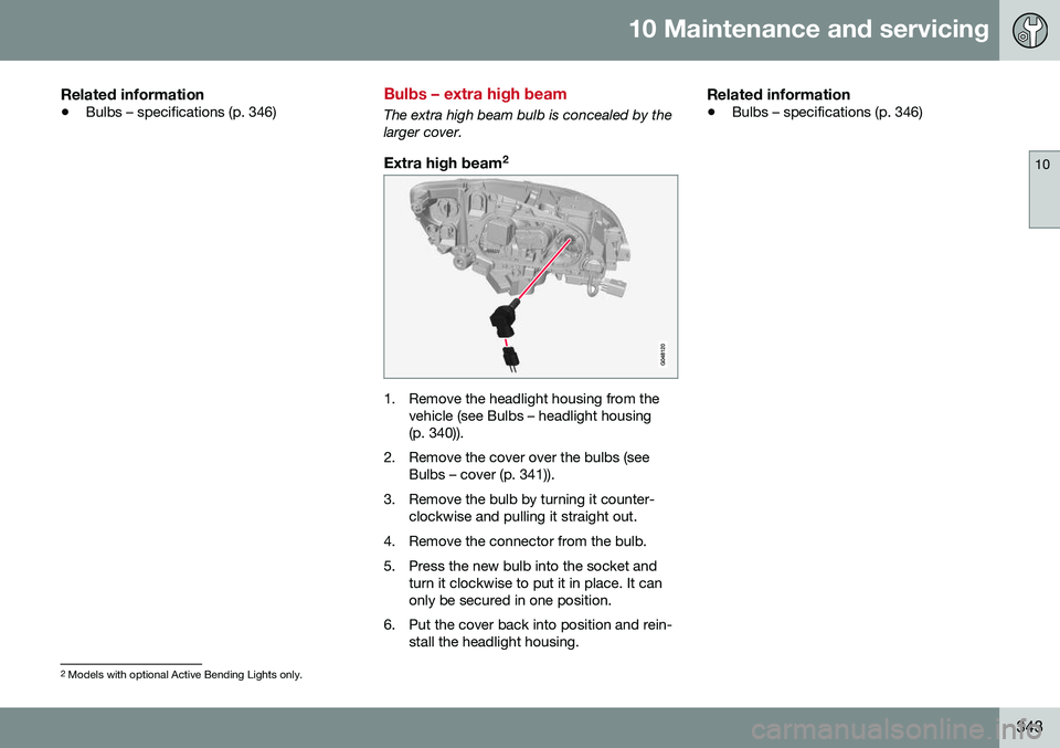
Bulbs – extra high beam
The extra high beam bulb is concealed by the larger cover.
Extra high beam 2
1. Remove the headlight housing from the
vehicle (see Bulbs – headlight housing (p. 340)).
2. Remove the cover over the bulbs (see Bulbs – cover (p. 341)).
3. Remove the bulb by turning it counter- clockwise and pulling it straight out.
4. Remove the connector from the bulb.
5. Press the new bulb into the socket and turn it clockwise to put it in place. It can only be secured in one position.
6. Put the cover back into position and rein- stall the headlight housing.
Related information
• Bulbs – specifications (p. 346)
2
Models with optional Active Bending Lights only.
Page 350 of 402

10 Maintenance and servicing
10
348
Wiper blades – windshield
The wiper blades should be replaced regularly for best effect. The windshield wiper blades must be in the vertical (service) position for replacement,washing or to lift them away from the wind-shield when e.g., removing ice or snow.
Replacing the windshield wiper blades
NOTE
The windshield wiper blades are different lengths. The blade on the driver’s side islonger than the one on the passenger side.
With the wipers in the service position, fold out the wiper arm from the wind-shield. Press the button on the wiperblade attachment and pull the wiperblade straight out, parallel with the wiperarm.
Slide in the new wiper blade until it clicks into place.
Check that the blade is securely in place.
4. Press the wipers back against the wind- shield.
To return the wipers from the service position to the normal position, fold the wipers backagainst the windshield and press the START/
STOP ENGINE button briefly to put the igni-
tion in mode I (or start the engine).
CleaningKeeping the windshield and wiper bladesclean helps improve visibility and prolongsthe service life of the wiper blades. Clean thewiper blades with a stiff-bristle brush andlukewarm soap solution or car washing deter-gent.
Related information
• Engine compartment – washer fluid (p. 349)
• Wiper blades – service position (p. 347)
Page 351 of 402
10 Maintenance and servicing
10
349
Wiper blades – tailgate
The wiper blades should be replaced regularly for best effect.
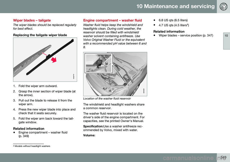
Replacing the tailgate wiper blade
G032770
1. Fold the wiper arm outward.
2. Grasp the inner section of wiper blade (atthe arrow).
3. Pull out the blade to release it from the wiper arm.
4. Press the new wiper blade into place and check that it seats securely.
5. Fold the wiper arm back toward the tail- gate window.
Related information
• Engine compartment – washer fluid (p. 349)
Engine compartment – washer fluid
Washer fluid helps keep the windshield and headlights clean. During cold weather, thereservoir should be filled with windshieldwasher solvent containing antifreeze. UseVolvo Original Washer Fluid or the equivalentwith a recommended pH value between 6 and8.
Location of the washer fluid reservoir
The windshield and headlight washers share a common reservoir. The washer fluid reservoir is located on the driver's side of the engine compartment. Forcapacities, see the printed Owner's Manual. Specification: Use a washer antifreeze rec-
ommended by Volvo, mixed with water. Volume: •
6.8 US qts (6.5 liters)
• 4.7 US qts (4.5 liters 4
)
Related information
• Wiper blades – service position (p. 347)
4
Models without headlight washers