2016 VOLVO S80 lane assist
[x] Cancel search: lane assistPage 8 of 380

Contents
6* Option/accessory, for more information, see Introduction.
07
Collision warning* – limitations............... 202
The camera’s limitations......................... 204
Collision warning – troubleshooting........ 205Collision warning – symbols and mes-
sages....................................................... 207
Driver Alert System................................. 209
Driver Alert Control (DAC) – introduction 209
Driver Alert Control (DAC) – operation.... 210
Driver Alert Control (DAC) – function...... 210
Driver Alert Control (DAC) – limitations... 211Driver Alert Control (DAC) – symbols and
messages................................................ 212 Lane Departure Warning (LDW) – intro-
duction.................................................... 214 Lane Departure Warning (LDW) – opera-
tion.......................................................... 214 Lane Departure Warning (LDW) - limita-
tions........................................................ 216 Lane Departure Warning (LDW) – sym-
bols and messages................................. 217
Park assist – introduction....................... 219
Park assist – function.............................. 219
Park assist – operation........................... 221
Park assist – limitations.......................... 222
Park assist – troubleshooting.................. 223
07
Rear Park Assist Camera (PAC) – intro-
duction.................................................... 223 Rear Park Assist Camera (PAC) – func-
tion.......................................................... 224 Rear Park Assist Camera (PAC) – opera-
tion.......................................................... 224 Rear Park Assist Camera (PAC) – guiding
and marker lines...................................... 225 Rear Park Assist Camera (PAC) – limita-
tions........................................................ 227
BLIS* – introduction................................ 227
BLIS* – function...................................... 228
BLIS* – operation.................................... 229
BLIS* – limitations................................... 229
BLIS* – messages................................... 230
08
08 Starting and driving
Starting the engine.................................. 233
Switching off the engine......................... 235Engine Remote Start (ERS)* – introduc-
tion.......................................................... 235 Engine Remote Start (ERS)* – starting the
engine..................................................... 236 Engine Remote Start (ERS)* – switching
off the engine.......................................... 236
Jump starting.......................................... 237
Transmission – general information........ 238
Transmission – positions........................ 238
Transmission – Geartronic...................... 240
Transmission – shiftlock override........... 242
Start/Stop – Hill Start Assist (HSA)......... 243
Start/Stop – introduction........................ 243
Start/Stop – function............................... 243
Start/Stop – Auto-stop exceptions......... 244
Start/Stop – Auto-start exceptions......... 245
Start/Stop – settings............................... 246
Start/Stop – symbols and messages...... 247
ECO*....................................................... 248
All Wheel Drive (AWD)............................. 250
Brakes – general..................................... 250
Brakes – symbols ................................... 252
Page 173 of 380

07 Driver support
07
}}
171
Resume set speedIf the cruise control has been deactivated temporarily, it can be reactivated by pressing
. The vehicle's speed returns to the most
recently set speed.
WARNING
There may be a significant increase in speed after the
button has been
pressed.
DeactivationThe Cruise control is disengaged by pressing
or by switching off the engine. The set
speed is cleared.
WARNING
Cruise control should not be used in heavy traffic or when driving on wet or slipperyroads. Cruise control may not maintain setspeed on steep downgrades.
Related information
• Cruise control (CC) – introduction (p. 168)
• Cruise control (CC) – engaging and set- ting speed (p. 168)
Adaptive Cruise Control – introduction
ACC is an optional system designed to assist the driver by maintaining a set speed or a settime interval to the vehicle ahead. It is primar-ily intended for use on long straight roads insteady traffic, such as on highways and othermain roads. When the driver has set the desired speed and the time interval to the vehicle ahead,ACC functions as follows:
• If there are no other vehicles in the lane ahead of you, your vehicle will travel atthe set speed.
• If ACC's radar sensor detects a slowermoving vehicle in the lane ahead, the sys-tem will adapt your vehicle's speed tohelp maintain the set time interval to thevehicle ahead. When there are no longerslower moving vehicles ahead, your vehi-cle will accelerate to resume the setspeed.
If ACC is switched off completely or in standby mode and your vehicle comes tooclose to another vehicle ahead, the driver willbe warned by the Distance Alert system (seeDistance Alert – introduction (p. 185)).WARNING
• Adaptive Cruise Control cannot cover all driving situations and traffic,weather and road conditions. The"Function" section provides informa-tion about limitations that the drivermust be aware of before using thisfeature.
• This system is designed to be a sup-plementary driving aid. It is not, how-ever, intended to replace the driver'sattention and judgement. The driver isresponsible for maintaining a safe dis-tance and speed and must intervene ifAdaptive Cruise Control does notmaintain a suitable speed or suitabledistance to the vehicle ahead.
• Maintenance of ACC components mayonly be performed by a trained andqualified Volvo technician.
Page 180 of 380

07 Driver support
07
178
Adaptive Cruise Control – passing another vehicle
Passing another vehicleIf your vehicle’s speed is being regulated by ACC and the driver indicates that he/shewould like to pass the vehicle ahead by usingthe left turn signal, ACC can assist by accel-
erating briefly. This function is active at speeds above approximately 45 mph (70 km/h).
WARNING
Please be aware that this function will also cause the vehicle to accelerate briefly incertain situations other than passinganother vehicle, for example using the leftturn signal to indicate a lane change or aturn toward a highway exit at speedsabove approximately 45 mph (70 km/h).
Related information
• Adaptive Cruise Control – introduction (p. 171)
Adaptive Cruise Control (ACC) – Queue Assist
Queue Assist is an added ACC feature that is linked to your vehicle's automatic transmis-sion.
IntroductionQueue Assist is an added ACC feature that islinked to your vehicle's automatic transmis-sion. Queue Assist consists of the following func- tions: •Enhanced speed interval (including when the vehicle is at a complete stop or ismoving at speed below 18 mph(30 km/h))
• Automatic standby mode when ACCchanges target vehicles
• No automatic braking when at a standstill
• The parking brake is applied automati-cally
Please note that the lowest speed that can be set is 18 mph (30 km/h), although ACC canmaintain a set speed/distance to a vehicleahead down to a standstill. Queue Assistconsists of the following features:
Enhanced speed interval
NOTE
The driver's door must be closed and the driver's seat belt must be fastened beforeACC can be put in active mode. If the driv-er's seat belt is taken off or if the driver'sdoor is opened, ACC will return to standbymode.
Your vehicle can maintain the set time interval to the vehicle ahead at any permissiblespeed, including a complete stop. In order to activate ACC at speeds below 18 mph (30 km/h):
• The vehicle ahead must be within a rea- sonable distance (not farther away thanapprox. 100 ft/30 meters)
• The lowest speed that can be selected is18 mph (30 km/h), although ACC will alsohelp maintain the set time interval to thevehicle ahead at lower speeds, includinga complete stop.
During short stops (less than approximately 3 seconds) in slow-moving traffic, your vehi-cle will begin moving again automatically assoon as the vehicle ahead begins to move. If it takes more than 3 seconds for the vehicle ahead to begin moving, ACC will be automat-ically go into standby mode.
Page 216 of 380

07 Driver support
07
214
Lane Departure Warning (LDW) – introduction
The LDW function is designed to help reduce the risk of accidents in situations where thevehicle unintentionally leaves its lane andthere is a risk of driving off the road or into theopposite lane.
Lane Departure Warning (LDW)
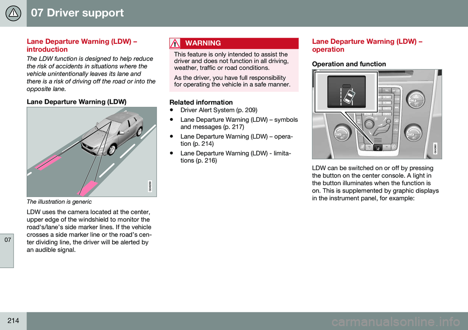
The illustration is genericLDW uses the camera located at the center, upper edge of the windshield to monitor theroad's/lane’s side marker lines. If the vehiclecrosses a side marker line or the road’s cen-ter dividing line, the driver will be alerted byan audible signal.
WARNING
This feature is only intended to assist the driver and does not function in all driving,weather, traffic or road conditions. As the driver, you have full responsibility for operating the vehicle in a safe manner.
Related information
• Driver Alert System (p. 209)
• Lane Departure Warning (LDW) – symbols and messages (p. 217)
• Lane Departure Warning (LDW) – opera-tion (p. 214)
• Lane Departure Warning (LDW) - limita-tions (p. 216)
Lane Departure Warning (LDW) – operation
Operation and function
LDW can be switched on or off by pressing the button on the center console. A light inthe button illuminates when the function ison. This is supplemented by graphic displaysin the instrument panel, for example:
Page 229 of 380

07 Driver support
07
}}
* Option/accessory, for more information, see Introduction.227
Rear Park Assist Camera (PAC) – limitations
LimitationsEven if a fairly small section of the screen image appears to be obstructed, this maymean that a relatively large area behind thevehicle is hidden and objects there may notbe detected until they are very near the vehi-cle.
NOTE
Bicycle carriers or other accessories mounted on the trunk may obstruct thecamera's field of view.
Keep in mind
• Keep the camera's lens free of dirt, ice and snow. Remove ice and snow care-fully to avoid scratching the lens.
• Clean the lens regularly with warm waterand a suitable car washing detergent.
Related information
•Rear Park Assist Camera (PAC) – intro-duction (p. 223)
• Rear Park Assist Camera (PAC) – opera-tion (p. 224)
• Park assist – introduction (p. 219)
BLIS* – introduction
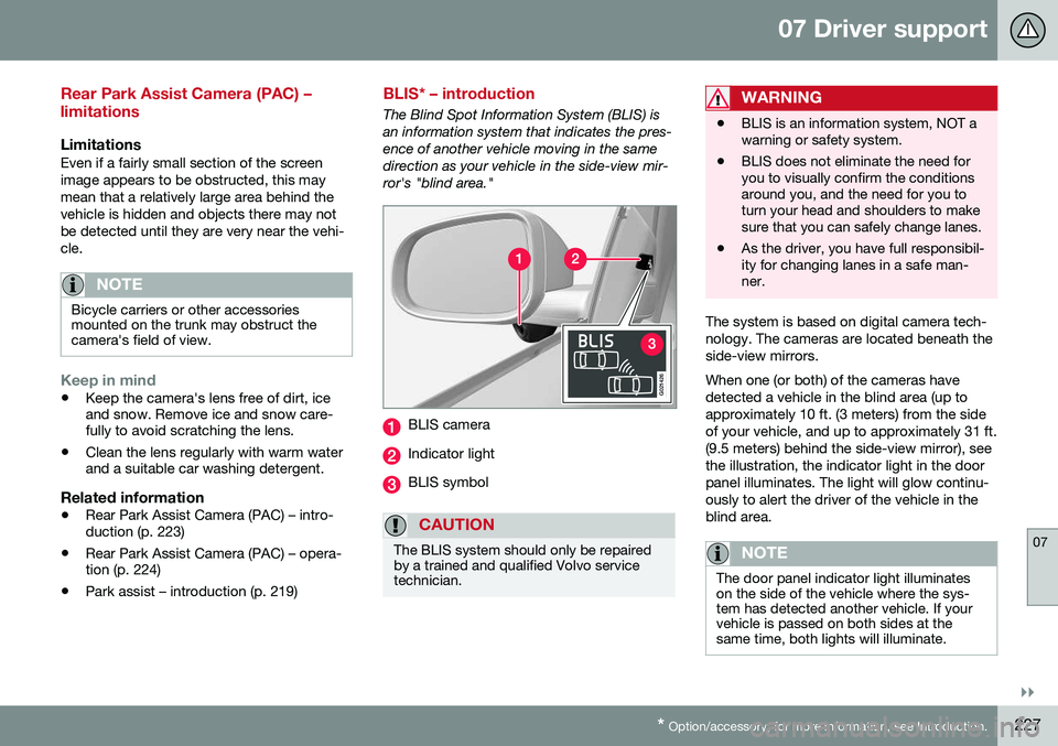
The Blind Spot Information System (BLIS) is an information system that indicates the pres-ence of another vehicle moving in the samedirection as your vehicle in the side-view mir-ror's "blind area."
G021426
BLIS camera
Indicator light
BLIS symbol
CAUTION
The BLIS system should only be repaired by a trained and qualified Volvo servicetechnician.
WARNING
• BLIS is an information system, NOT a warning or safety system.
• BLIS does not eliminate the need foryou to visually confirm the conditionsaround you, and the need for you toturn your head and shoulders to makesure that you can safely change lanes.
• As the driver, you have full responsibil-ity for changing lanes in a safe man-ner.
The system is based on digital camera tech- nology. The cameras are located beneath theside-view mirrors. When one (or both) of the cameras have detected a vehicle in the blind area (up toapproximately 10 ft. (3 meters) from the sideof your vehicle, and up to approximately 31 ft.(9.5 meters) behind the side-view mirror), seethe illustration, the indicator light in the doorpanel illuminates. The light will glow continu-ously to alert the driver of the vehicle in theblind area.
NOTE
The door panel indicator light illuminates on the side of the vehicle where the sys-tem has detected another vehicle. If yourvehicle is passed on both sides at thesame time, both lights will illuminate.