2016 TOYOTA MIRAI radiator
[x] Cancel search: radiatorPage 83 of 464

832. Fuel cell vehicle
2
Fuel cell system
MIRAI_OM_USA_OM62004U
The fuel cell vehicle has high-voltage components (about 650 V maxi-
mum) such as a fuel cell stack, traction battery, power control unit,
high-voltage cables (which are distinguished from low-voltage cables
by their orange covers), electric motor (traction motor), etc., and high-
temperature parts such as the radiator for cooling. Pay attention to all
warning labels attached to the vehicle.
This diagram is for illustrative purposes only and may differ from the
actual vehicle.
High-voltage and high-temperature components
Warning label
Power control unit
High-voltage cables (orange)
Fuel cell stack
Traction battery
Service plug
Fuel cell converter Electric motor (traction motor)
Air conditioning compressor
Radiator for inverter cooling
Radiator for fuel cell stack
cooling
Auxiliary inverter
Cabin coolant heater1
2
3
4
5
6
7
8
9
10
11
12
13
Page 211 of 464

2115-5. Using the driving support systems
5
Driving
MIRAI_OM_USA_OM62004U■
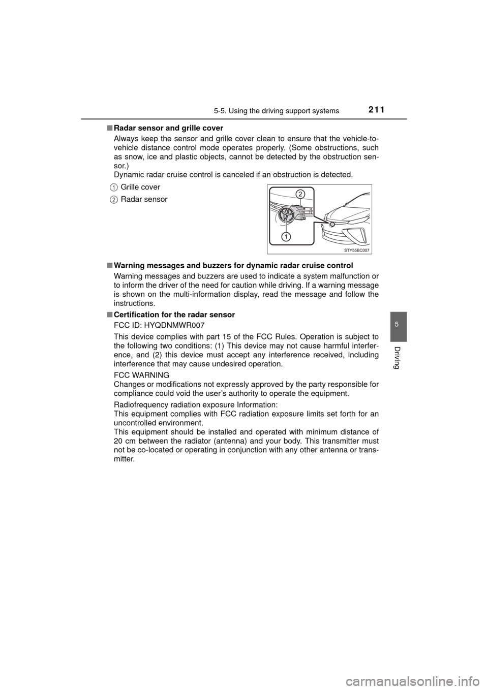
Radar sensor and grille cover
Always keep the sensor and grille cover clean to ensure that the vehicle-to-
vehicle distance control mode operates properly. (Some obstructions, such
as snow, ice and plastic objects, cannot be detected by the obstruction sen-
sor.)
Dynamic radar cruise control is canceled if an obstruction is detected.
■ Warning messages and buzzers for dynamic radar cruise control
Warning messages and buzzers are used to indicate a system malfunction or
to inform the driver of the need for caution while driving. If a warning message
is shown on the multi-information display, read the message and follow the
instructions.
■ Certification for the radar sensor
FCC ID: HYQDNMWR007
This device complies with part 15 of the FCC Rules. Operation is subject to
the following two conditions: (1) This device may not cause harmful interfer-
ence, and (2) this device must accept any interference received, including
interference that may cause undesired operation.
FCC WARNING
Changes or modifications not expressly approved by the party responsible for
compliance could void the user’s authority to operate the equipment.
Radiofrequency radiation exposure Information:
This equipment complies with FCC radiation exposure limits set forth for an
uncontrolled environment.
This equipment should be installed and operated with minimum distance of
20 cm between the radiator (antenna) and your body. This transmitter must
not be co-located or operating in conjunction with any other antenna or trans-
mitter. Grille cover
Radar sensor
1
2
Page 242 of 464

2425-5. Using the driving support systems
MIRAI_OM_USA_OM62004U■
Automatic cancelation of the pre-collision system
When a malfunction occurs due to sensor contamination, etc., that results in
the sensors being unable to detect obstacles, the pre-collision system will be
automatically disabled. In this case, the system will not activate even if there
is a collision possibility.
■ When there is a malfunction in the system, or if the system is tempo-
rarily unavailable
The PCS warning light flashes and a warning message is shown on the multi-
information display. If a warning message is shown on the multi-information
display, read the message and follow the instructions.
■ When the TRAC and VSC are turned off
●When the TRAC and VSC operations are turned off ( P. 234), the pre-colli-
sion brake assist and pre-collision braking are also turned off. However, the
alert function operates.
● The PCS warning light turns on and the “Pre-Collision Brake is Disabled due
to VSC OFF” is displayed on the multi-information display.
■ Certification for the radar sensor
FCC ID: HYQDNMWR007
This device complies with part 15 of the FCC Rules. Operation is subject to
the following two conditions: (1) This device may not cause harmful interfer-
ence, and (2) this device must accept any interference received, including
interference that may cause undesired operation.
FCC WARNING
Changes or modifications not expressly approved by the party responsible for
compliance could void the user’s authority to operate the equipment.
Radiofrequency radiation exposure Information:
This equipment complies with FCC radiation exposure limits set forth for an
uncontrolled environment.
This equipment should be installed and operated with minimum distance of
20 cm between the radiator (antenna) and your body. This transmitter must
not be co-located or operating in conjunction with any other antenna or trans-
mitter.
Page 303 of 464

3036-4. Other interior features
6
Interior features
MIRAI_OM_USA_OM62004U
Important! Read this information before using Safety Connect.
■Exposure to radio frequency signals
The Safety Connect system installed in your vehicle is a low-power
radio transmitter and receiver. It receives and also sends out radio
frequency (RF) signals.
In August 1996, the Federal Communications Commission (FCC)
adopted RF exposure gui delines with safety levels for mobile wire-
less phones. Those guidelines are consistent with the safety stan-
dards previously set by the fo llowing U.S. and international
standards bodies.
● ANSI (American National Stan dards Institute) C95.1 [1992]
● NCRP (National Council on Radiation Protection and Measure-
ment) Report 86 [1986]
● ICNIRP (Internationa l Commission on Non-Ionizing Radiation
Protection) [1996]
Those standards were based on comprehensive and periodic eval-
uations of the relevant scientific lit erature. Over 120 scientists, engi-
neers, and physicians from uni versities, and government health
agencies and industries reviewed t he available body of research to
develop the ANSI Standard (C95.1).
The design of Safety Connect complies with the FCC guidelines in
addition to those standards.
■ Certification for Safety Connect
FCC ID: O6Y-CDMRF101
FCC ID: XOECDMRF101B
FCC ID: N7NGTM2
FCC WARNING:
This equipment complies with FCC radiation exposure limits set forth for an uncon-
trolled environment and meets the FCC radio frequency (RF) Exposure Guidelines
in Supplement C to OET65. This equipmen t should be installed and operated keep-
ing the radiator at least 20cm or more aw ay from person’s body (excluding extremi-
ties: hands, wrists, feet and ankles).
Safety information for Safety Connect
Page 315 of 464

3157-2. Maintenance
MIRAI_OM_USA_OM62004U
7
Maintenance and care
General maintenance
Listed below are the general maintenance items that should be
performed at the intervals specified in the “Owner’s Warranty
Information Booklet” or “Owner’s Manual Supplement/Sched-
uled Maintenance Guide”. It is recommended that any problem
you notice should be brought to the attention of your Toyota
dealer or qualified service shop for advice.
Motor compartment
ItemsCheck points
Brake fluidIs the brake fluid at the correct
level? ( P. 326)
CoolantIs the coolant at the correct level?
(P. 324)
Radiator/condenser
The radiator and condenser should
be free from foreign objects.
(P. 325)
Washer fluidIs there sufficient washer fluid?
(P. 327)
Tr u nk
ItemsCheck points
12-volt battery Check the connections. ( P. 328)
Page 318 of 464

3187-3. Do-it-yourself maintenance
MIRAI_OM_USA_OM62004U
Do-it-yourself ser vice precautions
If you perform maintenance by yourself, be sure to follow the
correct procedure as given in these sections.
ItemsParts and tools
12-volt battery
condition
(P. 328)•Grease
• Conventional wrench (for terminal clamp bolts)
Brake fluid level
(P. 326)• FMVSS No.116 DOT 3 or SAE J1703 brake fluid
• Rag or paper towel
• Funnel (used only for adding brake fluid)
Inverter coolant
level ( P. 324)
• “Toyota Super Long Life Coolant” or a similar high
quality ethylene glycol-based non-silicate, non-
amine, non-nitrite and non-borate coolant with long-
life hybrid organic acid technology.
“Toyota Super Long Life Coolant” is pre-mixed with
50% coolant and 50% deionized water.
• Funnel (used only for adding coolant)
Fuses ( P. 355)• Fuse with same amperage rating as original
Light bulbs
(P. 358)
Radiator and con-
denser (
P. 325)
Tire inflation
pressure
( P. 346)• Tire pressure gauge
• Compressed air source
Washer fluid
(P. 327)• Water or washer fluid containing antifreeze (for win-
ter use)
• Funnel (used only for adding water or washer fluid)
Page 319 of 464

3197-3. Do-it-yourself maintenance
MIRAI_OM_USA_OM62004U
7
Maintenance and care
WARNING
The motor compartment contains many mechanisms and fluids that may
move suddenly, become hot, or become electrically energized. To avoid death
or serious injury, observe the following precautions.
■ When working on the motor compartment
●Be careful not to touch the high-voltage parts or hydrogen-related parts.
● Make sure that the “READY” indicator is off.
● Keep hands, clothing and tools away from the moving fans.
● Be careful not to touch the motor, inverter, radiator, etc., right after driving
as they may be hot. Coolant and other fluids may also be hot.
● Do not leave anything that may burn easily, such as paper and rags, in the
motor compartment.
● Do not smoke, cause sparks or expose an open flame to the 12-volt bat-
tery. 12-volt battery fumes are flammable.
● Be extremely cautious when working on the 12-volt battery. It contains poi-
sonous and corrosive sulfuric acid.
● Take care because brake fluid can harm your hands or eyes and damage
painted surfaces. If fluid gets on your hands or in your eyes, flush the
affected area with clean water immediately.
If you still experience discomfort, consult a doctor.
● Never touch, disassemble, remove or replace the high-voltage parts,
cables and their connectors. It can cause severe burns or electric shock
that may result in death or serious injury.
■ When working near the electric cooling fans or radiator grille
Be sure the power switch is off.
With the power switch in ON mode, t he electric cooling fans may automati-
cally start to run if the air conditioning is on and/or the coolant temperature
is high. ( P. 325)
■ Safety glasses
Wear safety glasses to prevent flying or falling material, fluid spray, etc.,
from getting in your eyes.
NOTICE
■If you remove the air cleaner filter
Driving with the air cleaner filter removed may cause excessive motor wear
due to dirt in the air.
Page 323 of 464

3237-3. Do-it-yourself maintenance
MIRAI_OM_USA_OM62004U
7
Maintenance and care
Motor compartment
Washer fluid tank (P. 327)
Brake fluid reservoir ( P. 326)
Inverter coolant reservoir ( P. 324)
Fuse boxes ( P. 355)
Fuel cell stack coolant radiator ( P. 325) Inverter coolant radiator
( P. 325)
Condenser ( P. 325)
Electric cooling fans
Fuel cell stack coolant reser-
voir ( P. 324)
Fuel cell stack coolant sub
radiator ( P. 325)1
2
3
4
5
6
7
8
9
10