2016 SUBARU WRX steering
[x] Cancel search: steeringPage 172 of 594

! Items of display message (for operation and vehicle condition) Item Icon “ ” information reminder Refer to page
Deactivation of the selection of the SI-DRIVE Sport Sharp (S#)
mode when the engine is cold —— 7-29, 7-31
Pedal operation for starting engine
— 7-12
Select lever into “ P ” operation ——
Access key warning* (The vehicle was driven while the access key
is not inside the vehicle.) — 3-28
Push-button ignition switch without “ OFF ” warning* —— 3-28
Access key lock-in warning* — 3-28
Emergency operation of push-button ignition switch* — 9-16
Release operation for steering lock* — 3-28
Power save function operation* —— 2-15
Key in the ignition switch reminder (if equipped) —— 3-5
Headlights ON warning —— 3-94
*: Models with keyless access with push-button start system Instruments and controls/Multi information display
– CONTINUED –3-43
Page 173 of 594

Instruments and controls/Multi information display
& Basic screensBy operating the “ ” or “ ” switch on the
steering wheel, you can change the
screen that is always displayed. Default screen: Journey time screen:
This screen displays the journey time (the
time that has elapsed since the ignition switch
was turned to the “ ON ” position).
Digital speedometer: SI-DRIVE mode screen:
This screen indicates the current SI-DRIVE
mode with its throttle angle.
Menu screen entering screen:
While this screen is selected, pull and hold the
“ /SET ” switch to enter the menu screen.3-44
Page 176 of 594

By operating the “ ” or “ ” switch on the
steering wheel, you can select the menu.
Pull the “
/SET ” switch to enter the
selected menu.
NOTE If you enter the “ Return ” menu, the
system will return to the previous
screen.
! Screen Settings
After entering the “ Screen Settings ” menu,
select one of the following menus.
! Welcome Good-bye Screen
The welcome screen/good-bye screens
can be activated or deactivated. Select
“ On ” to activate the screens. Select “ Off ”
to deactivate the screens.
! Gauge Initial Movement
The movement of the meter needles and
gauge needles that occurs when the
ignition switch is turned to the “ ON ”
position can be activated or deactivated.
Select “ On ” to activate. Select “ Off ” to
deactivate.
! Gear Position Indicator Setting
(MT models)
Display of the shift position indicator can
be activated or deactivated. Select “ On ” to
activate display of the shift position in- dicator or “ Off ” to deactivate it.
! Languages
Operate the “
” or “ ” switch on the
steering wheel to display the preferred
language. Then pull the “
/SET ” switch to
select the displayed language.
! REV settings (STI)
NOTE If the setting of the REV Indicator Light
is “ Off ” , the setting menus of the REV
Alarm Level Engine Speed and the REV
Buzzer are not displayed.
After entering the “ REV settings ” menu,
select any of the following menus.
! REV Indicator Light
Display of the REV indicator light can be
activated or deactivated. Select “ On ” to
activate display of the REV indicator light
or “ Off ” to deactivate it.
! REV Alarm Level Engine Speed
The alarm-level engine speed can be set
(in 100 rpm steps) within the range from
2,000 rpm to the red zone.
! REV Buzzer
The REV buzzer can be activated or
deactivated. Select “ On ” to activate the
REV buzzer or “ Off ” to deactivate it. ! EyeSight (models with EyeSight
system)
NOTE For models with the EyeSight system,
refer to the Owner ’ s Manual supple-
ment for the EyeSight system.
After entering the “ EyeSight ” menu, select
one of the following menus.
! Warning Volume
The volume of the warning buzzer that
sounds when the EyeSight system is in
use can be set in 3 stages ( “ Max ” , “ Mid ”
and “ Min ” ).
! Lead Vehicle Acquisition Sound
When adaptive cruise control is used, the
buzzer that sounds under any of the
following conditions can be activated or
deactivated.
. A vehicle is detected in front
. Detection is not possible
Select “ On ” to activate the buzzer. Select
“ Off ” to deactivate the buzzer.
! Lead Vehicle Moving Monitor
Function
When the lead vehicle moving monitor
function is operated, the buzzer that
sounds if a vehicle in front has started
can be activated or deactivated. SelectInstruments and controls/Multi information display
– CONTINUED –3-47
Page 184 of 594

! ECO history screen
1) Average fuel consumption per unit time
(bar graph)
2) Average fuel consumption corresponding
to the driving distance of each trip meter
(red line)
This screen displays the fuel economy
history for the vehicle using a bar graph.
The horizontal scale represents the past
time range and the vertical scale repre-
sents the fuel consumption. The green
bars show driving with good fuel economy
and the yellow bars show driving with poor
fuel economy.
The time range of the history can be set.
The width of the bar graph is adjusted as
follows depending on the set time range. Time range Width of bar graph
30 minutes 1 minute
60 minutes 2 minutes
120 minutes 4 minutes
For details about the setting, refer to
“ Economy history setting ” F 3-73.
! Vehicle activation status screen
When the vehicle stops
1) Steering axle When the vehicle is being driven regularly
1) Power train (illuminated in blue)
When the Vehicle Dynamics Control sys-
tem starts to activate, the tires illuminate in
yellow.
1) History of Vehicle Dynamics Control
system activationInstruments and controls/Multi function display
– CONTINUED –3-55
Page 228 of 594

Headlight beam leveler (if
equipped) & Automatic headlight beam
leveler (models with LED
headlights) The LED headlights generate more light
than conventional halogen headlights.
Therefore a driver of an oncoming vehicle
may experience too much glare if your
headlight beam height adjustment is high
when the vehicle is carrying a heavy load.
The automatic headlight beam leveler
adjusts the headlight beam height auto-
matically and optimally according to the
load being carried by the vehicle. Fog light switch (if equipped)
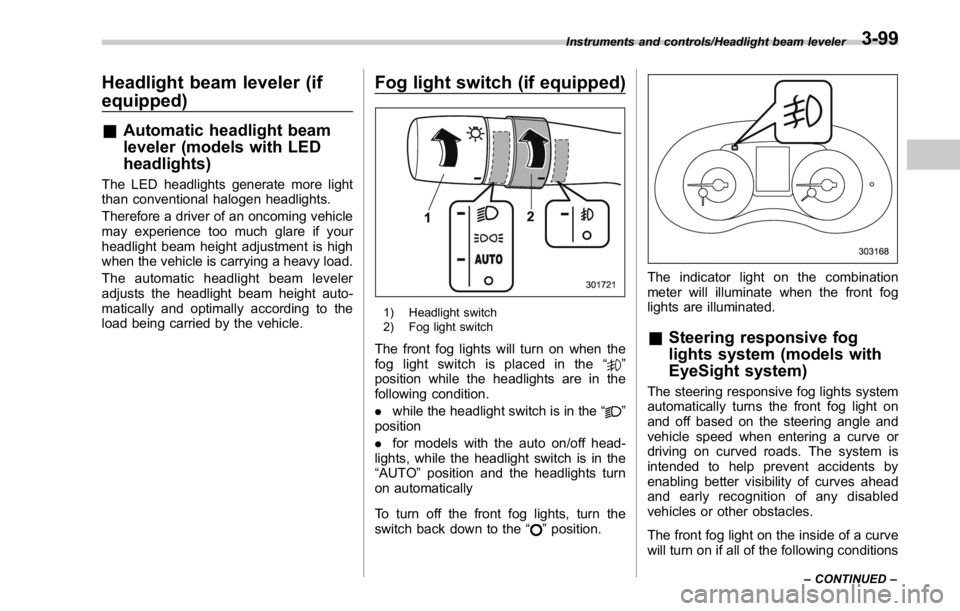
1) Headlight switch
2) Fog light switch
The front fog lights will turn on when the
fog light switch is placed in the “
”
position while the headlights are in the
following condition.
. while the headlight switch is in the “
”
position
. for models with the auto on/off head-
lights, while the headlight switch is in the
“ AUTO ” position and the headlights turn
on automatically
To turn off the front fog lights, turn the
switch back down to the “
” position. The indicator light on the combination
meter will illuminate when the front fog
lights are illuminated.
& Steering responsive fog
lights system (models with
EyeSight system) The steering responsive fog lights system
automatically turns the front fog light on
and off based on the steering angle and
vehicle speed when entering a curve or
driving on curved roads. The system is
intended to help prevent accidents by
enabling better visibility of curves ahead
and early recognition of any disabled
vehicles or other obstacles.
The front fog light on the inside of a curve
will turn on if all of the following conditionsInstruments and controls/Headlight beam leveler
– CONTINUED –3-99
Page 229 of 594

Instruments and controls/Fog light switch
are met.
. The light control switch is in the “
”
position
. The light control switch is in the
“ AUTO ” position and the low beam head-
lights turn on automatically
. The fog light switch is in the “
”
position
. The low beam mode is selected (the
turn signal lever is in the center position)
. The select lever is in a position other
than the “ R ” position
. The steering responsive fog lights
system has not been deactivated
. The operating conditions such as the
steering angle and vehicle speed are met
The front fog lights on both sides will turn
on as usual if all of the following conditions
are met.
. The light control switch is in the “
”
position
. The light control switch is in the
“ AUTO ” position and the low beam head-
lights turn on automatically
. The fog light switch is in the “
”
position
. The low beam mode is selected (the
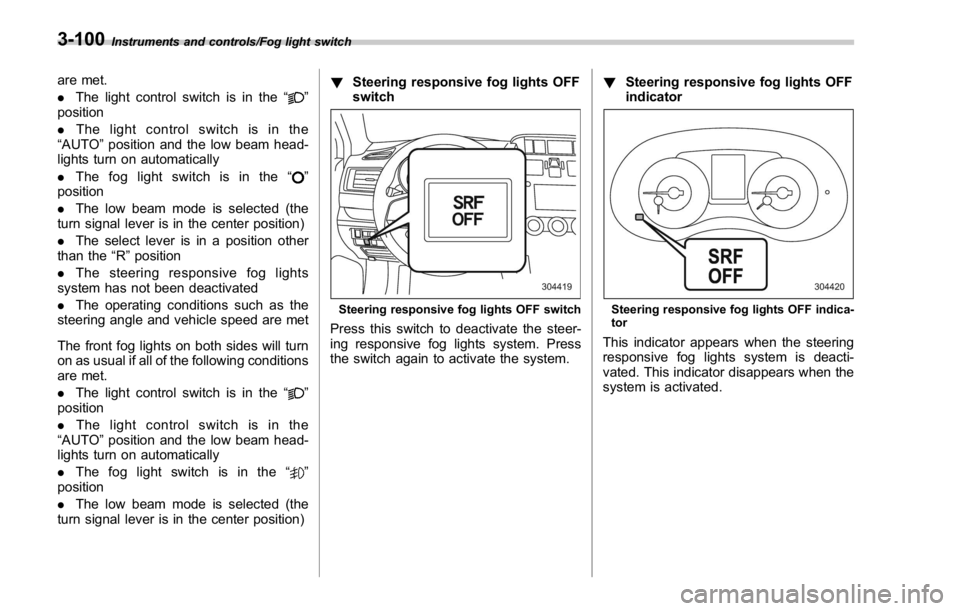
turn signal lever is in the center position) ! Steering responsive fog lights OFF
switch
Steering responsive fog lights OFF switch
Press this switch to deactivate the steer-
ing responsive fog lights system. Press
the switch again to activate the system. ! Steering responsive fog lights OFF
indicator
Steering responsive fog lights OFF indica-
tor
This indicator appears when the steering
responsive fog lights system is deacti-
vated. This indicator disappears when the
system is activated.3-100
Page 242 of 594

damage the conductors printed
on the window.
NOTE . Turn on the defogger and deicer
system if the wipers are frozen to the
windshield.
. If the windshield is covered with
snow, remove the snow so that the
windshield wiper deicer works effec-
tively.
. While the defogger and deicer sys-
tem is in the continuous operation
mode, if the vehicle speed remains at
9mph(15km/h)orlowerfor15
minutes, the windshield wiper deicer
automatically stops operating, though
the rear window defogger and outside
mirror defogger maintain continuous
operation in this condition.
. While the defogger and deicer sys-
tem is in the continuous operation
mode, if the battery voltage drops
below the permissible level, continu-
ous operation of the defogger and
deicer system is canceled and the
system stops operating. Tilt/telescopic steering wheel WARNING. Do not adjust the steering wheel
tilt/telescopic position while driv-
ing. This may cause loss of
vehicle control and result in
personal injury.
. If the lever cannot be raised to
the fixed position, adjust the
steering wheel again. It is dan-
gerous to drive without locking
the steering wheel. This may
cause loss of vehicle control
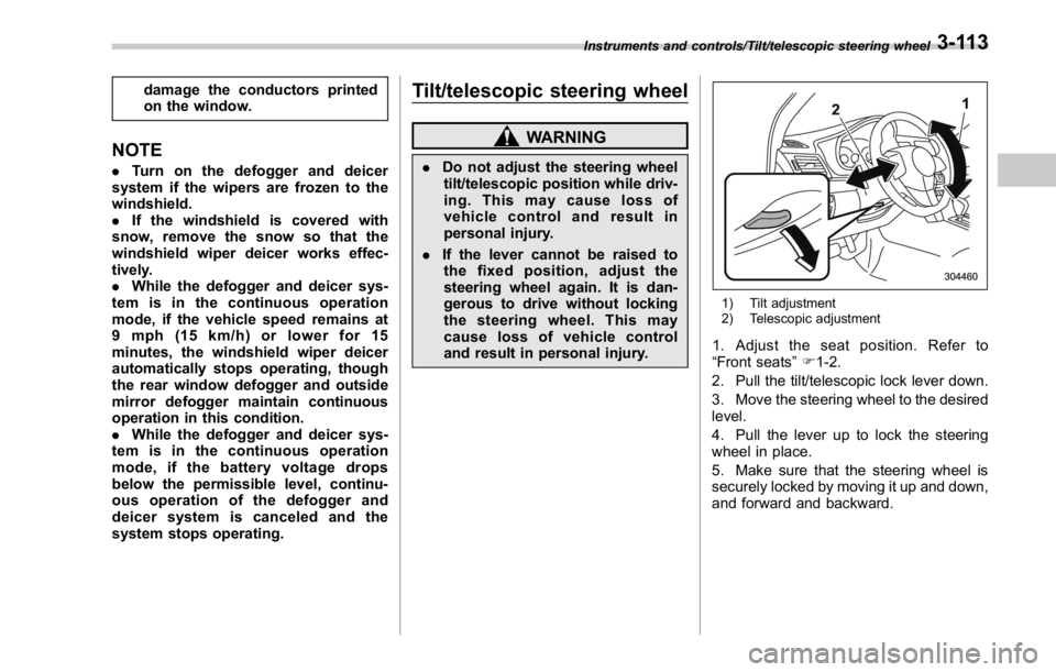
and result in personal injury. 1) Tilt adjustment
2) Telescopic adjustment
1. Adjust the seat position. Refer to
“ Front seats ” F 1-2.
2. Pull the tilt/telescopic lock lever down.
3. Move the steering wheel to the desired
level.
4. Pull the lever up to lock the steering
wheel in place.
5. Make sure that the steering wheel is
securely locked by moving it up and down,
and forward and backward.Instruments and controls/Tilt/telescopic steering wheel
3-113
Page 249 of 594

Climate control/Manual climate control operation
properly and become damaged, the sys-
tem may not be able to control the interior
temperature correctly. To avoid damaging
the sensors, observe the following pre-
cautions.
– Do not subject the sensors to impact.
– Keep water away from the sensors.
– Do not cover the sensors.
The sensors are located as follows.
– Solar sensor: beside the windshield
defroster grille
– Interior air temperature sensor: next to
the steering column
– Outside temperature sensor: near the
front bumper opening Manual climate control op-
eration & Airflow mode selection To select the airflow mode:
Type A: Turn the airflow mode selection
dial.
Type B: Press the airflow mode selection
button.
To select the defrost mode:
Press the defroster button.
Airflow modes are as follows.
(Ventilation): Instrument panel outlets (Bi-level): Instrument panel outlets and
foot outlets
(Heat): Foot outlets, both side outlets of
the instrument panel and some through
windshield defroster outlets (A small
amount of air flows to the windshield and4-6