2016 SUBARU WRX brake
[x] Cancel search: brakePage 161 of 594

Instruments and controls/Warning and indicator lights
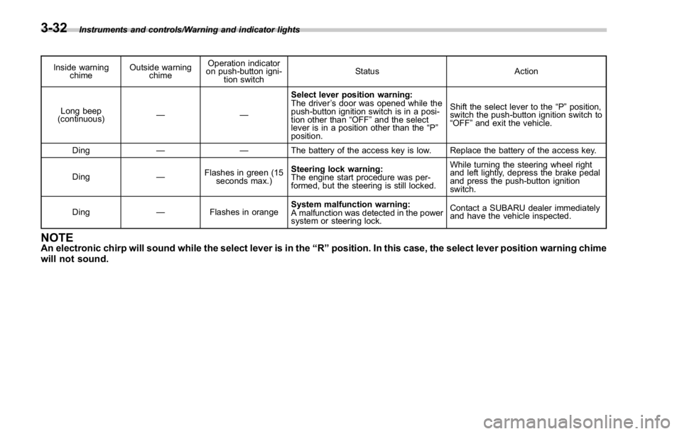
Inside warning
chime Outside warning
chime Operation indicator
on push-button igni-
tion switch Status Action
Long beep
(continuous) —— Select lever position warning:
The driver ’ s door was opened while the
push-button ignition switch is in a posi-
tion other than “ OFF ” and the select
lever is in a position other than the “ P ”
position. Shift the select lever to the “ P ” position,
switch the push-button ignition switch to
“ OFF ” and exit the vehicle.
Ding —— The battery of the access key is low. Replace the battery of the access key.
Ding — Flashes in green (15
seconds max.) Steering lock warning:
The engine start procedure was per-
formed, but the steering is still locked. While turning the steering wheel right
and left lightly, depress the brake pedal
and press the push-button ignition
switch.
Ding — Flashes in orange System malfunction warning:
A malfunction was detected in the power
system or steering lock. Contact a SUBARU dealer immediately
and have the vehicle inspected.
NOTE An electronic chirp will sound while the select lever is in the “ R ” position. In this case, the select lever position warning chime
will not sound.3-32
Page 170 of 594

Item Icon “ ” information reminder Refer to page
ABS malfunction warning Yellow 3-20
Vehicle Dynamics Control system malfunction warning Yellow 3-26
Brake system warning Red 3-21
Electronic parking brake system malfunction warning Red 3-22
Brake fluid level warning Red 3-21
Low fuel warning Yellow 3-24
Windshield washer fluid level warning Yellow 3-18
Hill start assist system malfunction warning Yellow 3-24
Door/trunk lid open warning — 3-25
AWD system malfunction warning (if equipped) Yellow 3-25
Electric power steering system malfunction warning (except STI) Red 3-25Instruments and controls/Multi information display
– CONTINUED –3-41
Page 185 of 594

Instruments and controls/Multi function display
When the Vehicle Dynamics Control sys-
tem activates, the tires illuminate in yellow
and the Vehicle Dynamics Control system
operating indicator flashes.
1) Activation status of the ABS (Anti-lock
Brake System)
2) Vehicle Dynamics Control system oper-
ating indicator (flashing in yellow)
3) History of Vehicle Dynamics Control
system activation ! Triple meter screen
Triple meter screen (display example)
This screen displays up to three optional
pieces of information that can be selected
from the following items.
The items shown in the triple meter screen
can be changed. For details, refer to
“ Triple meter setting ” F 3-75. Item Details
Average vehicle speed (Average
vehicle speed for the entire driving
time from when the trip meter was
reset)
Lifetime fuel consumption
Engine oil temperature (except
STI)
Accelerator opening ratio
Journey distance (the distance
that has been driven since the
ignition switch was turned to the
“ ON ” position)
Average fuel consumption for the
entire driving distance from when
the ignition switch was turned to
the “ ON ” position
Boost pressure3-56
Page 226 of 594

& Daytime running light system WARNINGThe brightness of the illumination of
the high beam headlights is reduced
by the daytime running light system.
The light switch must always be
turned to the “
” position when it
is dark outside.
The high beam headlights will automati-
cally illuminate at reduced brightness
when the following conditions are fulfilled.
. The engine is running.
. The parking brake is fully released.
. The light control switch is in the
“ AUTO ” (if equipped), “
” or off position.
. For CVT models, the select lever is in a
position other than the “ P ” position.
NOTE . When the light switch is in the “ ”
position, the instrument panel illumina-
tion, front side marker lights, tail lights
and license plate lights are also illumi-
nated.
. For models with the auto on/off
headlights, while the light control
switch is in the “ AUTO ” position and
the system is activated to the auto-on
mode depending on the ambient light level, the high beam headlights that
have illuminated at reduced brightness
turn off, and the low beam headlights
turn on alternatively. At this time, the
instrument panel illumination, front
side marker lights, tail lights and
license plate lights are also illuminated.
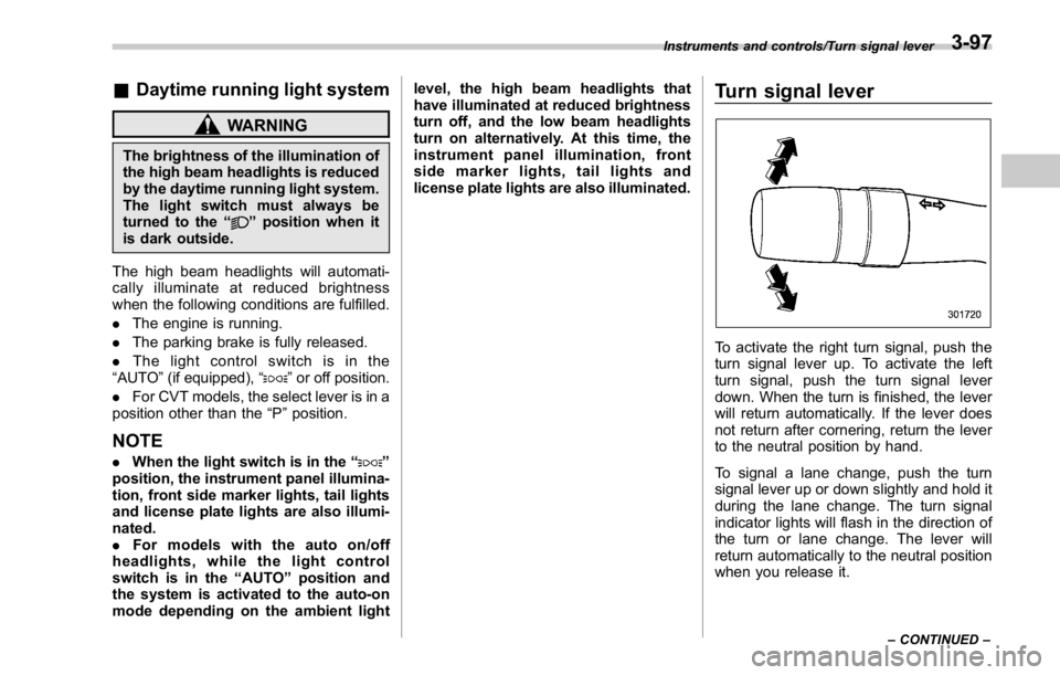
Turn signal lever
To activate the right turn signal, push the
turn signal lever up. To activate the left
turn signal, push the turn signal lever
down. When the turn is finished, the lever
will return automatically. If the lever does
not return after cornering, return the lever
to the neutral position by hand.
To signal a lane change, push the turn
signal lever up or down slightly and hold it
during the lane change. The turn signal
indicator lights will flash in the direction of
the turn or lane change. The lever will
return automatically to the neutral position
when you release it. Instruments and controls/Turn signal lever
– CONTINUED –3-97
Page 260 of 594

Basic information before use & Initial screen ! Initial screen
1. When the ignition switch is in the
“ ACC ” or “ ON ” position, the initial screen
will be displayed and the system will begin
operating.
. When using the STARLINK function,
the display screen may be different
from the screen above.
. After a few seconds, the “ Caution
(Caution) ” screen will be displayed.
. After about 5 seconds, the “ Caution
(Caution) ” screen automatically
switches to the next screen. WARNINGWhen the vehicle is stopped with the
engine running, always apply the
parking brake for safety. & Loading and unloading a disc ! Loading a disc
CAUTIONNever try to disassemble the audio
kit or lubricate any part of the CD
player. Do not insert anything other
than a disc into the slot.
1. Insert a disc into the disc slot.
. After insertion, the disc is automati-
cally loaded. Audio/Basic information before use
– CONTINUED –5-5
Page 377 of 594

Interior equipment/Cup holders
Cup holders CAUTIONTake care to avoid spills. Beverages,
if hot, might burn you and/or your
passengers. Spilled beverages may
also damage upholstery, carpets or
audio equipment.
& Front passenger ’ s cup holder
CAUTIONDo not pick up a cup from the cup
holder or put a cup in the holder
while you are driving, as this may
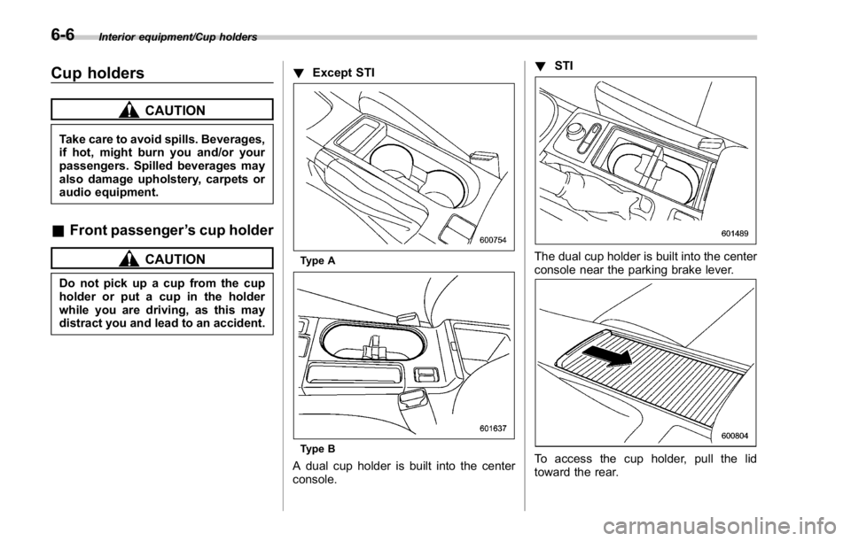
distract you and lead to an accident. ! Except STI
Type A
Type B
A dual cup holder is built into the center
console. ! STI
The dual cup holder is built into the center
console near the parking brake lever.
To access the cup holder, pull the lid
toward the rear.6-6
Page 380 of 594

appliance that can be connected
is 120W. Do not use an appliance
which exceeds the indicated wat-
tage for each outlet.
When using appliances con-
nected to two or more outlets
simultaneously, the total power
consumed by them must not
exceed 120W. Overloading the
accessory power outlet can
cause a short circuit. Do not use
double adapters or more than
one electrical appliance.
. If the plug on your electric appli-
ance is either too loose or too
tight for the accessory power
outlet, this can result in a poor
contact or cause the plug to get
stuck. Only use plugs that fit
properly.
. Use of an electric appliance in the
accessory power outlet for a long
period of time while the engine is
not running can cause battery
discharge.
. Before driving your vehicle, make
sure that the plug and the cord
on your electrical appliance will
not interfere with your shifting
gears and operating the accel-
erator and brake pedals. If they do, do not use the electrical
appliance while driving.
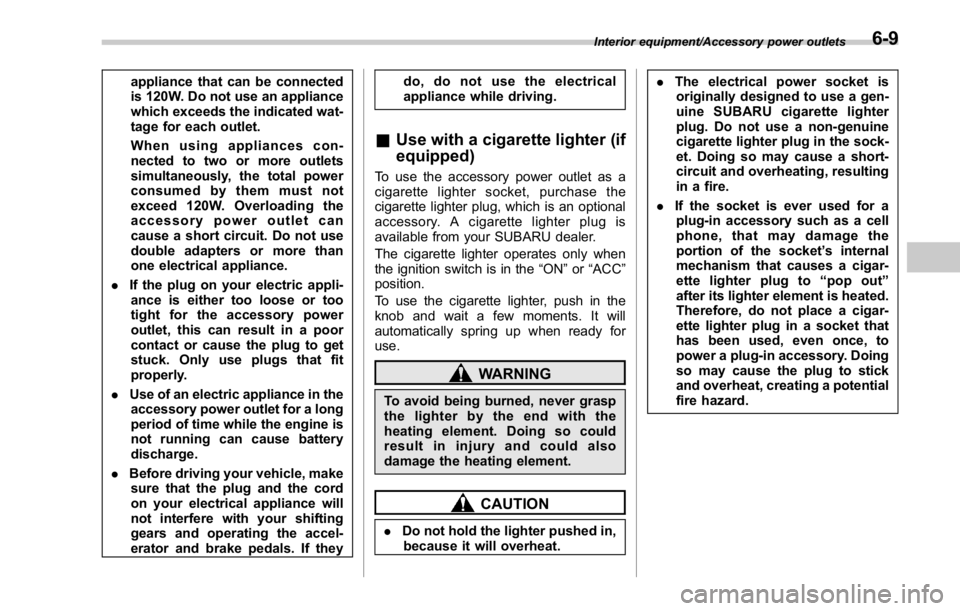
& Use with a cigarette lighter (if
equipped) To use the accessory power outlet as a
cigarette lighter socket, purchase the
cigarette lighter plug, which is an optional
accessory. A cigarette lighter plug is
available from your SUBARU dealer.
The cigarette lighter operates only when
the ignition switch is in the “ ON ” or “ ACC ”
position.
To use the cigarette lighter, push in the
knob and wait a few moments. It will
automatically spring up when ready for
use.
WARNING
To avoid being burned, never grasp
the lighter by the end with the
heating element. Doing so could
result in injury and could also
damage the heating element.
CAUTION
. Do not hold the lighter pushed in,
because it will overheat. . The electrical power socket is
originally designed to use a gen-
uine SUBARU cigarette lighter
plug. Do not use a non-genuine
cigarette lighter plug in the sock-
et. Doing so may cause a short-
circuit and overheating, resulting
in a fire.
. If the socket is ever used for a
plug-in accessory such as a cell
phone, that may damage the
portion of the socket ’ s internal
mechanism that causes a cigar-
ette lighter plug to “ pop out ”
after its lighter element is heated.
Therefore, do not place a cigar-
ette lighter plug in a socket that
has been used, even once, to
power a plug-in accessory. Doing
so may cause the plug to stick
and overheat, creating a potential
fire hazard.Interior equipment/Accessory power outlets
6-9
Page 390 of 594

Fuel ...................................................................... 7-3Fuel requirements ............................................... 7-3
Fuel filler lid and cap ........................................... 7-5
State emission testing (U.S. only) ...................... 7-7
Preparing to drive ............................................... 7-8
Starting and stopping the engine (models
without push-button start system) .................. 7-9Starting engine .................................................... 7-9
Stopping the engine ........................................... 7-11
Starting and stopping engine (models with
push-button start system) .............................. 7-12Safety precautions ............................................. 7-12
Operating range for push-button start
system ............................................................. 7-12
Starting engine ................................................... 7-12
Stopping engine ................................................. 7-14
When access key does not operate properly ....... 7-14
Remote engine start system (dealer
option) .............................................................. 7-14Models with “ keyless access with push-button
start system ” ................................................... 7-15
Entering the vehicle while it is running via remote
start ................................................................. 7-16
Entering the vehicle following remote engine start
shutdown ......................................................... 7-16
Pre-heating or pre-cooling the interior of the
vehicle ............................................................. 7-16
System maintenance .......................................... 7-16
Manual transmission .......................................... 7-17
Shifting speeds .................................................. 7-18
Driving tips ........................................................ 7-18 Driver ’ s Control Center Differential (C.DIFF/
DCCD) (STI) ..................................................... 7-19To change mode of driver ’ s control center
differential ....................................................... 7-20
Auto mode ........................................................ 7-20
Manual mode ..................................................... 7-21
Temporary release ............................................. 7-23
Continuously variable transmission ................. 7-23Select lever ....................................................... 7-24
Selection of manual mode .................................. 7-26
Shift lock function ............................................. 7-27
Driving tips ........................................................ 7-28
SI-DRIVE (STI) .................................................... 7-29Intelligent (I) mode ............................................. 7-29
Sport (S) mode .................................................. 7-30
Sport Sharp (S#) mode. ...................................... 7-30
SI-DRIVE selector .............................................. 7-30
SI-DRIVE (except STI: CVT models) ................. 7-31Intelligent (I) mode ............................................. 7-31
Sport (S) mode .................................................. 7-31
Sport Sharp (S#) mode. ...................................... 7-32
SI-DRIVE switches ............................................. 7-32
Limited slip differential (LSD) (STI) .................. 7-33
Power steering ................................................... 7-33
STI .................................................................... 7-33
Except STI ......................................................... 7-34
Braking ............................................................... 7-35
Braking tips ....................................................... 7-35
Brake system .................................................... 7-35
Disc brake pad wear warning indicators ............. 7-36Starting and operating
7