2016 SUBARU IMPREZA test mode
[x] Cancel search: test modePage 55 of 594
Seat, seatbelt and SRS airbags/Front seatbelt pretensioners
&System monitors
A diagnostic system continually monitors
the readiness of the seatbelt pretensioner
while the vehicle is being driven. The
seatbelt pretensioners share the control
modulewiththeSRSairbagsystem.
Therefore, if any malfunction occurs in a
seatbelt pretensioner, the SRS airbag
system warning light will illuminate. For
details, refer to “SRS airbag system
monitors ”F 1-67.
& System servicing
WARNING
. When discarding a seatbelt re-
tractor assembly or scrapping
the entire vehicle damaged by a
collision, consult your SUBARU
dealer.
. Tampering with or disconnecting
the system’ s wiring could result
in accidental activation of the
seatbelt pretensioner and/or
SRS airbag or could make the
system inoperative, which may
result in serious injury. Do not
use electrical test equipment on
any circuit related to the seatbelt
pretensioner and SRS airbag
systems. For required servicing of the seatbelt pretensioner, con-
sult your nearest SUBARU deal-
er.
CAUTION
The sensors and SRS airbag control
modules are located in the following
locations.
.
Front sub sensors: on both the
right and left side at the front of
the vehicle
. Front door impact sensors: on
both front doors
. Satellite safing sensor: under the
rear center seat
. SRS airbag control module (in-
cluding the impact sensors): un-
der the center of the instrument
panel
If you need service or repair in those
areas or near the front seatbelt
retractors, have the work performed
by your authorized SUBARU dealer.
NOTE
If the front or side part of the vehicle is
damaged in an accident to the extent
that the seatbelt pretensioner does not operate, contact your SUBARU dealer
as soon as possible.
&
Precautions against vehicle
modification
Always consult your SUBARU dealer if
you want to install any accessory parts to
your vehicle.
CAUTION
Do not perform any of the following
modifications. Such modifications
can interfere with proper operation
of the seatbelt pretensioners.
. Attachment of any equipment
(bush bar, winches, snow plow,
skid plate, etc.) other than genu-
ine SUBARU accessory parts to
the front end.
. Modification of the suspension
system or front end structure.
. Installation of a tire of different
size and construction from the
tires specified on the vehicle
placard attached to the driver ’s
door pillar or specified for indivi-
dual vehicle models in this Own-
er ’s Manual.
1-24
Page 357 of 594
Audio/Voice command system
!Commands for changing the audio
mode
Voice command Function
Change to AM Switch to AM mode
Change to AM1 Switch to AM mode
band 1
Change to AM2 Switch to AM mode
band 2
Change to FM Switch to FM mode
Change to FM1 Switch to FM mode
band 1
Change to FM2 Switch to FM mode
band 2
Change to FM3 Switch to FM mode
band 3
Change to SiriusXM Switch to XM mode
Change to BT Audio Switch to Bluetooth
Audio mode
Change to CD Switch to CD mode
Change to USB Switch to USB mode
Change to iPod Switch to iPod mode
Change to aha Switch to aha radio
mode
Change to Pandora Switch to Pandora
mode
Change to AUX Switch to AUX mode
!
Commands for hands-free phone
Voice command Function
Dial Number ?<0-9,
+, *, #> ?Change
number, Dial Places a call to the
said phone number
Dial <0-9, +, *, #> ?
Change number, Dial
Contacts, Phonebook
?
? Dial Make a call by using
the phonebook
Call
<1-5> ?Dial
Call History ?In-
coming call, Outgoing
call ?Next (page),
Previous (page) ?
<1-5> ?Dial Make a call by using
the call history
Incoming Calls Display the call his-
tory screen
Outgoing Calls Display the call his-
tory screen
Redial Places a call to the
phone number of the
latest outgoing call
Callback Places a call to the
phone number of the
latest incoming call
Select Phone ?
<1-5> Display the phone
select screen
Phone Menu Display the hands
free top screen
!
Commands for Pandora
Voice command Function
Like Mark “Like ”flag
Dislike Mark“Dislike ”flag
Skip, Next Skip to the next song
!
Commands for aha
Voice command Function
Thumbs Up, Heart,
Like Mark
“Like ”flag
Thumbs Down, Ban,
Dislike Mark
“Dislike ”flag
Refresh, update Refresh the selected
station to get the lat-
est information
Content Up Playback next Con-
tent
Content Down Playback previous
Content
5-86
Page 386 of 594

Fuel...................................................................... 7-3Fuel requirements ............................................... 7-3
Fuel filler lid and cap ........................................... 7-4
State emission testing (U.S. only) ...................... 7-7
Preparing to drive ............................................... 7-8
Starting and stopping the engine (models without push-button start system) .................. 7-9
Starting engine.................................................... 7-9
Stopping the engine ........................................... 7-11
Starting and stopping engine (models with
push-button start system) .............................. 7-12
Safety precautions............................................. 7-12
Operating range for push-button start system ............................................................. 7-12
Starting engine ................................................... 7-12
Stopping engine ................................................. 7-13
When access key does not operate properly ....... 7-14
Remote engine start system (dealer
option) .............................................................. 7-14
Models with “keyless access with push-button
start system ”................................................... 7-15
Models without “keyless access with push-button
start system ”................................................... 7-16
Entering the vehicle while it is running via remote start ................................................................. 7-19
Entering the vehicle following remote engine start shutdown ......................................................... 7-19
Pre-heating or pre-cooling the interior of the vehicle ............................................................. 7-19
Service mode (models without “keyless access
with push-button start system ”)........................ 7-19 Remote transmitter program (models without
“keyless access with push-button start
system ”).......................................................... 7-19
System maintenance .......................................... 7-20
Manual transmission ......................................... 7-22Shifting speeds.................................................. 7-22
Driving tips ........................................................ 7-23
Continuously variable transmission ................. 7-23Continuously variable transmission features . ..... 7-24
Select lever ....................................................... 7-24
Selection of manual mode (if equipped) .............. 7-26
Selection of “L”(if equipped) ... .......................... 7-28
Shift lock function ............................................. 7-28
Driving tips ........................................................ 7-29
Power steering ................................................... 7-30Power steering warning light .............................. 7-30
Power steering system features ......................... 7-30
Braking............................................................... 7-31Braking tips ....................................................... 7-31
Brake system .................................................... 7-31
Disc brake pad wear warning indicators ............. 7-32
ABS (Anti-lock Brake System).......................... 7-32ABS self-check.................................................. 7-32
ABS warning light .............................................. 7-33
Electronic Brake Force Distribution (EBD)
system ............................................................. 7-33
Steps to take if EBD system malfunctions .......... 7-33
Vehicle Dynamics Control system.................... 7-34Safety precautions............................................. 7-34
System features ................................................. 7-35
Vehicle Dynamics Control system monitor .......... 7-36
Starting and operating
7
Page 392 of 594
spilled fuel is not covered under
the SUBARU Limited Warranty.
. Always use a genuine SUBARU
fuel filler cap. If you use the
wrong cap, it may not fit or have
proper venting and your fuel tank
and emission control system
may be damaged. It could also
lead to fuel spillage and a fire.
. Immediately put fuel in the tank
whenever the low fuel warning
light illuminates. Engine misfires
as a result of an empty tank
could cause damage to the en-
gine. Continuing to operate your
vehicle at an extremely low fuel
level may result in a reduction of
engine performance.State emission testing
(U.S. only)
WARNING
Testing of an All-Wheel Drive model
must NEVER be performed on a
single two-wheel dynamometer. At-
tempting to do so will result in
uncontrolled vehicle movement and
may cause an accident or injuries to
persons nearby.
CAUTION
. At state inspection time, remem-
ber to tell your inspection or
service station in advance not to
place your SUBARU AWD vehicle
on a two-wheel dynamometer.
Otherwise, serious transmission
damage will result.
. Resultant vehicle damage due to
improper testing is not covered
under the SUBARU Limited War-
ranty and is the responsibility of
the state inspection program or
its contractors or licensees.
California and a number of federal states have Inspection/Maintenance programs to
inspect your vehicle
’s emission control
system. If your vehicle does not pass this
test, some states may deny renewal of
your vehicle’ s registration.
Your vehicle is equipped with a computer
that monitors the performance of the
engine’ s emission control system. Certi-
fied emission inspectors will inspect the
On-Board Diagnostic (OBDII) system as
part of the state emission inspection
process. The OBDII system is designed
to detect engine and transmission pro-
blems that might cause the vehicle emis-
sions to exceed allowable limits. OBDII
inspections apply to all 1996 model year
and newer passenger cars and trucks.
Over 30 states plus the District of Colum-
bia have implemented emission inspec-
tion of the OBDII system.
. The inspection of the OBDII system
consists of a visual operational check of
the “CHECK ENGINE ”warning light/mal-
function indicator light (MIL) and an
examination of the OBDII system with an
electronic scan tool.
. A vehicle
passes the OBDII system
inspection if proper operation of the
“ CHECK ENGINE ”warning light is ob-
served, there are no stored diagnostic
trouble codes, and the OBDII readiness
monitors are all complete.
Starting and operating/State emission testing (U.S. only)
–CONTINUED –7-7
Page 410 of 594
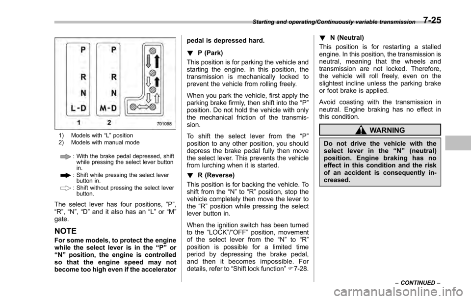
1) Models with“L ” position
2) Models with manual mode
: With the brake pedal depressed, shift while pressing the select lever button
in.
: Shift while pressing the select leverbutton in.
: Shift without pressing the select lever
button.
The select lever has four positions, “P”,
“R ”, “N ”,“D ”and it also has an “L”or “M”
gate.
NOTE
For some models, to protect the engine
while the select lever is in the “P ” or
“N ”position, the engine is controlled
so that the engine speed may not
become too high even if the accelerator pedal is depressed hard.
!
P (Park)
This position is for parking the vehicle and
starting the engine. In this position, the
transmission is mechanically locked to
prevent the vehicle from rolling freely.
When you park the vehicle, first apply the
parking brake firmly, then shift into the “P”
position. Do not hold the vehicle with only
the mechanical friction of the transmis-
sion.
To shift the select lever from the “P”
position to any other position, you should
depress the brake pedal fully then move
the select lever. This prevents the vehicle
from lurching when it is started.
! R (Reverse)
This position is for backing the vehicle. To
shift from the “N”to “R”position, stop the
vehicle completely then move the lever to
the “R”position while pressing the select
lever button in.
When the ignition switch has been turned
to the “LOCK”/“OFF ”position, movement
of the select lever from the “N ” to “R ”
position is possible for a limited time
period by depressing the brake pedal,
and then it becomes impossible. For
details, refer to “Shift lock function ”F 7-28. !
N (Neutral)
This position is for restarting a stalled
engine. In this position, the transmission is
neutral, meaning that the wheels and
transmission are not locked. Therefore,
the vehicle will roll freely, even on the
slightest incline unless the parking brake
or foot brake is applied.
Avoid coasting with the transmission in
neutral. Engine braking has no effect in
this condition.
WARNING
Do not drive the vehicle with the
select lever in the “N ” (neutral)
position. Engine braking has no
effect in this condition and the risk
of an accident is consequently in-
creased.
Starting and operating/Continuously variable transmission
–CONTINUED –7-25
Page 499 of 594
Maintenance and service/Maintenance precautions
erative. NEVER use a circuit
tester for this wiring. If your
SRS airbag or seatbelt preten-
sioner needs service, consult
your nearest SUBARU dealer.
NOTE
SUBARU does not endorse the use of
non-SUBARU approved flushing sys-
tems and strongly advises against
performing these services on a
SUBARU vehicle. Non-SUBARU ap-
proved flushing systems use chemi-
cals and/or solvents which have not
been tested or approved by SUBARU.
SUBARU warranties do not cover any
part of the vehicle which is damaged by
adding or applying chemicals and/or
solvents other than those approved or
recommended by SUBARU.
&Before checking or servicing
in the engine compartment
WARNING
. Always stop the engine and apply
the parking brake firmly to pre-
vent the vehicle from moving.
. Always let the engine cool down.
Engine parts become very hot when the engine is running and
remain hot for some time after
the engine has stopped.
. Do not spill engine oil, engine
coolant, brake fluid or any other
fluid on hot engine components.
This may cause a fire.
. When the ignition switch is in the
“ON ”position, the cooling fan
may operate suddenly even
when the engine is stopped. If
your body or clothes come into
contact with a rotating fan, that
could result in serious injury. To
avoid risk of injury, perform the
following precautions.
– Models with push-button start
system:
Always turn the push-button
ignition switch to the “OFF”
position and confirm that the
operation indicator on the
switch is turned off. Then take
the access key out from the
vehicle.
– Models without push-button
start system:
Always remove the key from
the ignition switch.
. Before performing any servicing
on a vehicle equipped with a remote engine start system (a
dealer option), temporarily place
the remote engine start system in
service mode to prevent it from
unexpectedly starting the engine.
&
When checking or servicing
in the engine compartment
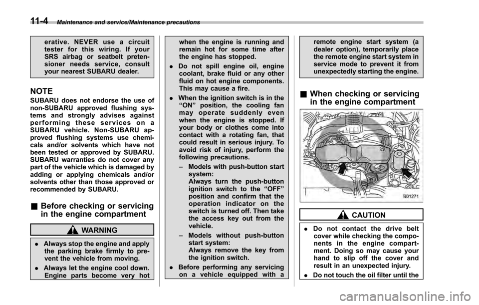
CAUTION
. Do not contact the drive belt
cover while checking the compo-
nents in the engine compart-
ment. Doing so may cause your
hand to slip off the cover and
result in an unexpected injury.
. Do not touch the oil filter until the
11-4