2016 SUBARU IMPREZA lights
[x] Cancel search: lightsPage 419 of 594
Starting and operating/Vehicle Dynamics Control system
system warning light and ABS warning
light illuminate simultaneously.
The EBD system may be malfunctioning if
the brake system warning light and ABS
warning light illuminate simultaneously
during driving.
Even if the EBD system malfunctions, the
conventional braking system will still func-
tion. However, the rear wheels will be
more prone to locking when the brakes
are applied harder than usual and the
vehicle’s motion may therefore become
somewhat harder to control.
If the brake system warning light and ABS
warning light illuminate simultaneously,
take the following steps.
1. Stop the vehicle in the nearest safe,
flat location.
2. Apply the parking brake and turn off
the engine.
3. Restart the engine.
4. Release the parking brake.
Even if both warning lights turn off:
The EBD system may be malfunctioning.
Drive carefully to the nearest SUBARU
dealer and have the system inspected.
If both warning lights illuminate again
and remain illuminated after restarting
the engine:
1. Turn off the engine again. 2. Apply the parking brake.
3. Check the brake fluid level. For details
about checking the brake fluid level, refer
to
“Checking the fluid level ”F 11-16.
. If the brake fluid level is not below the
“MIN ”mark, the EBD system may be
malfunctioning. Drive carefully to the
nearest SUBARU dealer and have the
system inspected.
. If the brake fluid level is below the
“MIN ”mark, DO NOT drive the vehicle.
Instead, have the vehicle towed to the
nearest SUBARU dealer for repair.
WARNING
. Driving with the brake system
warning light illuminated is dan-
gerous. This indicates your brake
system may not be working
properly. If the light remains
illuminated, have the brakes in-
spected by a SUBARU dealer
immediately.
. If at all in doubt about whether
the brakes are operating prop-
erly, do not drive the vehicle.
Have your vehicle towed to the
nearest SUBARU dealer for re-
pair.
Vehicle Dynamics Control
system
& Safety precautions
WARNING
Always use the utmost care in
driving –overconfidence because
you are driving a vehicle with the
Vehicle Dynamics Control system
could easily lead to a serious acci-
dent.
CAUTION
. Even if your vehicle is equipped
with Vehicle Dynamics Control
system, winter tires should be
used when driving on snow-cov-
ered or icy roads; in addition,
vehicle speed should be reduced
considerably. Simply having a
Vehicle Dynamics Control sys-
tem does not guarantee that the
vehicle will be able to avoid
accidents in any situation.
. Activation of the Vehicle Dy-
namics Control system is an
indication that the road being
travelled on has a slippery sur-
7-34
Page 439 of 594
Starting and operating/BSD/RCTA (5–door models —if equipped)
&BSD/RCTA approach indica-
tor light/warning buzzer
When the BSD/RCTA is active, the BSD/
RCTA approach indicator light will operate
to alert the driver when there are vehicles
in the neighboring lanes. When reversing
the vehicle, the BSD/RCTA approach
indicator light and warning buzzer will
operate to alert the driver that a vehicle
is approaching from the left or right side.
! BSD/RCTA approach indicator light
BSD/RCTA approach indicator light
It is mounted in each side of the outside
mirrors and will illuminate when a vehicle
approaching from behind is detected. If an
indicator light is illuminated and the turn
signal lever is operated toward the side in
which this light turned on, the indicator light flashes to warn the driver of dangers.
When reversing the vehicle, the indicator
light flashes when the system detects a
vehicle approaching from either side.
! BSD/RCTA approach indicator
light dimming function
When the headlights are turned on, the
brightness of the BSD/RCTA approach
indicator light will be reduced.
NOTE
. When affected by direct sunlight,
you may have difficulty recognizing
the BSD/RCTA approach indicator light.
. When affected by the headlight
beams from the vehicles behind, you
may have difficulty recognizing the
BSD/RCTA approach indicator light.
. While the illumination brightness
control dial is in the fully upward
position, even if the headlights are
turned on, the brightness of the BSD/
RCTA approach indicator light will not
be reduced. For details about the
illumination brightness control dial,
refer to “Illumination brightness con-
trol” F3-93.
! BSD/RCTA approach warning buz-
zer (only when reversing)
A warning buzzer sounds along with
flashing of the BSD/RCTA approach in- dicator light to warn the driver of dangers.
The setting of the warning buzzer volume
can be changed by operating the multi
information display of the combination
meter. For details, refer to
“BSD/RCTA”
F 3-42.
! Safety tips regarding the BSD/RCTA
approach indicator light/warning
buzzer
. In the following cases, operation of the
BSD/RCTA approach indicator light and
the warning buzzer may be delayed or the
system may fail to issue these warnings.
–When a vehicle moves to the
neighboring lane from a lane next to
the neighboring lane
– When driving on a steep incline or
on repeated sharp uphill and downhill
grades
– When going beyond a pass
– When both your vehicle and a
vehicle driving on a neighboring lane
are driving on the far side of each lane.
– When several narrowly-spaced ve-
hicles are approaching in a row
– In low radius bends (tight bends or
when making turns at an intersection)
– When there is a difference in height
between your lane and the neighbor-
ing lane
– Immediately after the BSD/RCTA is
7-54
Page 461 of 594
Driving tips/Trailer towing (Crosstrek models)
maximum gross weight. The chains
should cross under the trailer tongue to
prevent the tongue from dropping onto the
ground in case it should disconnect from
the hitch ball. Allow sufficient slack in the
chains taking tight turn situations into
account; however, be careful not to let
them drag on the ground.
WARNING
Do not connect safety chains to any
part of the vehicle other than the
safety chain hooks.
Hitch harness connector
8. Connect the hitch wire harness’s black
four-pin wire connector to the towing
trailer ’s wire harness. 9. Confirm proper function of the hitch
wire harness by individually activating the
brake, stop and turn signal lights on the
trailer.
NOTE
Always disconnect the trailer wire har-
ness before launching or retrieving a
watercraft.
&
If not towing a trailer
. Remove the ball mount from the hitch
receiver tube and insert the receiver cover
onto the hitch receiver tube.
. Place the dust cap over the four-pin
connector of the hitch wire harness to
protect against possible damage.
. Occasionally lubricate terminals of the
four-pin connector using terminal grease.
Trailer towing (Crosstrek
models)
CAUTION
This “Trailer towing ”section is
applicable for Crosstrek models.
Other vehicle models are neither
designed nor intended to be used
for trailer towing. Therefore, never
tow a trailer with other vehicle
models.
Your vehicle is designed and intended to
be used primarily as a passenger-carrying
vehicle. Towing a trailer puts additional
loads on your vehicle’ s engine, drivetrain,
brakes, tires and suspension and has an
adverse effect on fuel economy.
If you do decide to tow a trailer, your safety
and satisfaction depend upon proper use
of correct equipment and cautious opera-
tion of your vehicle. Seek the advice of
your SUBARU dealer to assist you in
purchasing a hitch and other necessary
towing equipment appropriate for your
vehicle. Do not use towing equipment
other than genuine SUBARU towing
equipment. In addition, be sure to follow
the instructions for proper installation and
use provided by the trailer or caravan ’s
8-18
Page 467 of 594
Driving tips/Trailer towing (Crosstrek models)
!Trailer lights
CAUTION
Direct splicing or other improper
connection of trailer lights may
damage your vehicle ’s electrical
system and cause a malfunction of
your vehicle ’s lighting system.
Connection of trailer lights to your vehi-
cle ’s electrical system requires modifica-
tions to the vehicle’ s lighting circuit to
increase its capacity and accommodate
wiring changes. To ensure the trailer lights
are connected properly, please consult
your SUBARU dealer. Check for proper
operation of the turn signals and the brake
lights each time you connect a trailer to
your vehicle.
! Tires
WARNING
Never tow a trailer when the tem-
porary spare tire is used. The tem-
porary spare tire is not designed to
sustain the towing load. Use of the
temporary spare tire when towing
can result in failure of the spare tire
and/or less stability of the vehicle.
Make sure that all the tires on your vehicle are properly inflated. Refer to
“Tires”F 12-
8.
Trailer tire condition, size, load rating and
proper inflation pressure should be in
accordance with the trailer manufacturer ’s
specifications. Also check federal, state,
province and/or other applicable regula-
tions.
In the event your vehicle gets a flat tire
when towing a trailer, ask a commercial
road service representative or profes-
sional to repair the flat tire.
If you carry a regular size spare tire in your
vehicle or trailer as a precaution against
getting a flat tire, be sure that the spare
tire is firmly secured.
& Trailer towing tips
CAUTION
. For models equipped with the
BSD (Blind Spot Detection) and
RCTA (Rear Cross Traffic Alert)
driving support systems, when
towing a trailer, press the BSD/
RCTA OFF switch to deactivate
the system. The system may not
operate properly due to the
blocked radar waves. For details
about the BSD/RCTA OFF switch, refer to
“BSD/RCTA OFF switch ”
F 7-56.
. Never exceed 45 mph (72 km/h)
when towing a trailer in hilly
country on hot days.
. When towing a trailer, steering,
stability, stopping distance and
braking performance will be dif-
ferent when compared to normal
operation. For safety’ s sake, you
should employ extra caution
when towing a trailer and you
should never drive at excessive
speeds. You should also keep the
following tips in mind:
! Before starting out on a trip
. Check the towing regulations for trailer
or caravan vehicles that vary by state/
region. Failure to comply with the proce-
dures set forth will not only compromise
your safety, but will also negate your
insurance coverage and/or may violate
the state road and traffic acts and regula-
tions.
. Check that the vehicle and vehicle-to-
hitch mounting are in good condition. If
any problems are apparent, do not tow the
trailer.
. Check that the vehicle rests horizon-
tally with the trailer attached. If the vehicle
8-24
Page 468 of 594
is tipped sharply up at the front and down
at the rear, check the total trailer weight,
GVW, GAWs and tongue load again, then
confirm that the load and its distribution
are acceptable.
.Check that the tire rating and pressures
are correct.
. Check that the vehicle and trailer are
connected properly. Confirm that:
–the trailer tongue is connected
properly to the hitch ball.
– the trailer lights connector is con-
nected properly and trailer ’s brake
lights illuminate when the vehicle ’s
brake pedal is pressed, and that the
trailer ’s turn signal lights flash when
the vehicle’ s turn signal lever is oper-
ated.
– the safety chains are connected
properly.
– all cargo in the trailer is secured
safely in position.
– the side mirrors provide a good
rearward field of view without a sig-
nificant blind spot.
. Sufficient time should be taken to learn
the “feel ”of the vehicle/trailer combination
before starting out on a trip. In an area free
of traffic, practice turning, stopping and
backing up. !
Driving with a trailer
. You should allow for considerably more
stopping distance when towing a trailer.
Avoid sudden braking because it may
result in skidding or jackknifing and loss of
control.
. Avoid abrupt starts and sudden accel-
erations. If your vehicle has a manual
transmission, always start out in first gear
and release the clutch at moderate engine
revolution.
. Avoid uneven steering, sharp turns and
rapid lane changes.
. Slow down before turning. Make a
longer than normal turning radius because
the trailer wheels will be closer than the
vehicle wheels to the inside of the turn. In
a tight turn, the trailer could hit your
vehicle.
. Crosswinds will adversely affect the
handling of your vehicle and trailer, caus-
ing sway. Crosswinds can be due to
weather conditions or the passing of large
trucks or buses. If swaying occurs, firmly
grip the steering wheel and promptly begin
decelerating your vehicle at a gradual
pace.
. When passing other vehicles, consid-
erable distance is required because of the
added weight and length caused by
attaching the trailer to your vehicle.
1) Left turn
2) Right turn
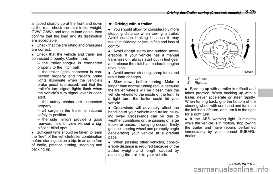
. Backing up with a trailer is difficult and
takes practice. When backing up with a
trailer, never accelerate or steer rapidly.
When turning back, grip the bottom of the
steering wheel with one hand and turn it to
the left for a left turn, and turn it to the right
for a right turn.
. If the ABS warning light illuminates
while the vehicle is in motion, stop towing
the trailer and have repairs performed
immediately by your nearest SUBARU
dealer.
Driving tips/Trailer towing (Crosstrek models)
–CONTINUED –8-25
Page 480 of 594

&How to jump start
1. Make sure the booster battery is 12
volts and the negative terminal is
grounded.
2. If the booster battery is in another
vehicle, do not let the two vehicles touch.
3. Turn off all unnecessary lights and
accessories.
4. Connect the jumper cables exactly in
the sequence illustrated.
In case of emergency/Jump starting
–CONTINUED –9-11
Page 497 of 594
Maintenance and service
Tire rotation..................................................... 11-26
Tire replacement .............................................. 11-27
Wheel replacement ........................................... 11-28
Aluminum wheels............................................. 11-28
Windshield washer fluid .................................. 11-28
Adding the windshield washer fluid .................. 11-29
Windshield washer fluid ................................... 11-29
Replacement of wiper blades .......................... 11-30Windshield wiper blade assembly ..................... 11-30
Windshield wiper blade rubber ......................... 11-31
Rear window wiper blade assembly .................. 11-32
Rear window wiper blade rubber ....................... 11-32
Battery............................................................... 11-34
Fuses ................................................................ 11-35
Installation of accessories ............................... 11-36 Replacing bulbs
............................................... 11-36
Headlights (models with HID headlights) ........... 11-36
Headlights (models without HID headlights) ...... 11-37
Front turn signal light ...................................... 11-38
Parking light .................................................... 11-38
Front fog light (if equipped) .............................. 11-38
Rear combination lights ................................... 11-38
License plate light ........................................... 11-41
Map light ......................................................... 11-42
Dome light and cargo area light ....................... 11-42
Trunk light ....................................................... 11-43
Other bulbs ..................................................... 11-43
Replacing key battery ...................................... 11-43Safety precautions........................................... 11-43
Replacing battery of access key ....................... 11-44
Replacing transmitter battery ........................... 11-45
Page 530 of 594
Fuses
CAUTION
Never replace a fuse with one hav-
ing a higher rating or with material
other than a fuse because serious
damage or a fire could result.
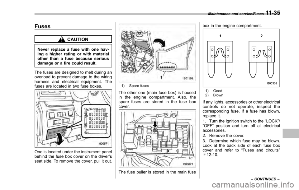
The fuses are designed to melt during an
overload to prevent damage to the wiring
harness and electrical equipment. The
fuses are located in two fuse boxes.
One is located under the instrument panel
behind the fuse box cover on the driver ’s
seat side. To remove the cover, pull it out.
1) Spare fuses
The other one (main fuse box) is housed
in the engine compartment. Also, the
spare fuses are stored in the fuse box
cover.
The fuse puller is stored in the main fuse box in the engine compartment.
1) Good
2) Blown
If any lights, accessories or other electrical
controls do not operate, inspect the
corresponding fuse. If a fuse has blown,
replace it.
1. Turn the ignition switch to the
“LOCK”/
“OFF ”position and turn off all electrical
accessories.
2. Remove the cover.
3. Determine which fuse may be blown.
Look at the back side of each fuse box
cover and refer to “Fuses and circuits”
F 12-10.
Maintenance and service/Fuses
–CONTINUED –11-35