Page 49 of 324

The essentials
How does the manual air conditioning work*? Fig. 56
In the centre console: Manual air condi-
tioning c ontr
ols To switch a specific function on, press the ap-
pr
opri
at
e button. Press the button again to
switch off the function. The LED on each control lights up to indicate
that the r
espective function of a control has
been switched on.
1TemperatureTurn the control to adjust the temperature
2FanSetting 0: blower and manual air conditioning switched off
Level 6: maximum fan level.
3Air distributionRotate the continuous control to direct the airflow to the desired area.
Defrost functionThe airflow is directed at the windscreen. Air recirculation is automatically switched off or is not switched on. Increase the fan power to clear the
windscreen of condensation as soon as possible. To dehumidify the air, the cooling system will automatically switch on.
The air is directed at the chest of driver and passengers by the dash panel air vents.
Distribution of air towards the chest and the footwell area.»
47
Page 50 of 324
The essentials
Air distribution towards the footwell.
Air distribution towards the windscreen and the footwell.
Heated rear window: this only works when the engine is running and switches off automatically after a maximum of 10 minutes.
Air recirculation
Seat heating buttons
Maximum cooling power. The recirculation of air and the cooling system turn on automatically and air distribution adjusts automatically to the
position
››› in Introduction on page 163
›››
page 163 How does the heating and the fresh air system work?
Fig. 57
In the centre console: heating system and
fre sh air c
ontrols. 48
Page 51 of 324

The essentials
To switch a specific function on, press the ap-
pr opri
at
e button. Press the button again to
switch off the function. The LED on each control lights up to indicate
that the r
espective function of a control has
been switched on.
1TemperatureTurn the control to adjust the temperature. The temperature cannot be lower than that of the exterior air temperature, as this system cannot cool
or dehumidify the air
2FanSetting 0: blower, heating and fresh air systems switched off
Level 6: maximum fan level
3Air distributionRotate the continuous control to direct the airflow to the desired area.
Defrost functionThe airflow is directed at the windscreen.
The air is directed at the chest of driver and passengers by the dash panel air vents.
Distribution of air towards the chest and the footwell area.
Air distribution towards the footwell.
Air distribution towards the windscreen and the footwell.
Heated rear window: this only works when the engine is running and switches off automatically after a maximum of 10 minutes
Air recirculation
››› page 166
Seat heating buttons
››› in Introduction on page 163
›››
page 163 49
Page 52 of 324

The essentials
Fluid Level control Fi l
lin
g capacities
Tank level
Petrol and diesel
engines50 l, of which, approx. 7 l reserveVehicles with all-wheel-drive :
55 l, of which, approx. 8.5 l re- serve
Natural gas en-
ginea)approx. 15 kg
a)
The capacity depends on the efficacy and characteristics of
the natural gas pumps. The capacity indicated is based on a
minimum loading pressure of 200 bar.
Capacity of the windscreen washer fluid container
Versions without
headlight washer
systemapprox. 3 litres
Versions with
headlight washer
systemapprox. 5 litres Fuel
Fig. 58
Fuel tank flap with tank cap attached. The flap that covers the tank cap is unlocked
and loc
k
ed aut
omatically using the central
locking.
Opening the fuel tank cap
● Open the fuel tank flap by pressing on the
left
side.
● Unscrew the cap by turning it to the left.
● Place it in the space on the hinge of the
open flap ››
› Fig. 58.
Closing the fuel tank cap
● Unscrew the cap by turning it to the right as
far as
it will go.
● Close the lid.
››› in Filling up on page 257
›››
page 256 Oil
Fig. 59
Engine oil dipstick. Fig. 60
In the engine compartment: Engine
oi l
fi
ller cap 50
Page 53 of 324

The essentials
The level is measured using the dipstick loca-
t ed in the en
gine c
ompartment
››› page 262.
The oil should leave a mark between zones A and
C . It should never exceed zone
A .
● Zone A : Do not add oil.
● Zone B : You can add oil but keep the level
in th at
zone.
● Zone C : Add oil up to zone
B .
T op
pin
g up engine oil
● Unscrew cap from oil filler opening.
● Add oil slowly.
● At the same time, check the level to ensure
you do not a
dd too much.
● When the oil level reaches at least zone B ,
u n
s
crew the engine oil filler cap carefully.
Oil properties
Engine typeSpecification
Petrol without flexible
service intervalVW 502 00/VW 504 00
Petrol with flexible serv-
ice interval (LongLife)VW 504 00
Diesel. Engines without
Particulate filter (DPF)VW 505 01/VW 506 01/VW
507 00
Engine typeSpecification
Diesel. Particulate Filter
Engines (DPF).
With or without flexible
service interval (with
and without LongLife) a)VW 507 00
Natural gas enginesVW 502 00
a)
Only use recommended oils, otherwise you may damage the
engine.
Engine oil additives
No type of additive should be mixed with the
engine oil. The deterioration caused by these
additives is not covered by the warranty.
››› in Changing engine oil on page 266
››› page 264 Coolant
Fig. 61
Engine compartment: coolant expan-
s ion t
ank
cap. The coolant tank is located in the engine
c
omp
ar
tment ›››
page 262.
When the engine is cold, replace the coolant
when the level is below .
Coolant specifications
The engine cooling system is supplied from
the factory with a specially treated mixture of
water and at least 40 % of the additive G13
(TL-VW 774 J), purple. This mixture gives the
necessary frost protection down to -25°C
(-13°F) and protects the light alloy parts of
the engine cooling system against corrosion.
It also prevents scaling and considerably rai-
ses the boiling point of the coolant.
To protect the cooling system, the percentage
of additive must always be at least 40 %, » 51
Page 54 of 324

The essentials
even in warm climates where anti-freeze pro-
t ection i
s
not required.
If for weather reasons further protection is
necessary, the proportion of additive may be
increased, but only up to 60 %; otherwise an-
tifreeze protection will diminish and this will
worsen cooling.
When the coolant is topped up, use a mixture
of distilled water and at least 40 % of the
G13 or G12 plus-plus (TL-VW 774 G) additive
(both are purple) to obtain an optimum anti-
corrosion protection ››› in Topping up cool-
ant on p ag
e 267
. The mixture of G13 with
G12 plus (TL-VW 774 F), G12 (red) or G11
(green-blue) engine coolants will significant-
ly reduce anti-corrosion protection and
should therefore be avoided ››› in Topping
up c oo
l
ant on page 267.
››› in Topping up coolant on page 267
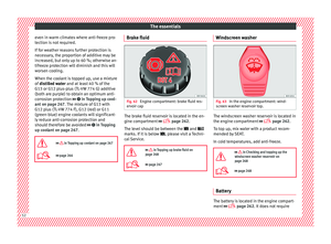
››› page 266 Brake fluid
Fig. 62
Engine compartment: brake fluid res-
er v
oir c
ap The brake fluid reservoir is located in the en-
gine c
omp
ar
tment ›››
page 262.
The level should be between the and
marks. If it is below , please visit a Techni-
cal Service.
››› in Topping up brake fluid on
page 268
››› page 267 Windscreen washer
Fig. 63
In the engine compartment: wind-
s c
r
een washer reservoir top. The windscreen washer reservoir is located in
the en
gine c
omp
artment ›››
page 262.
To top up, mix water with a product recom-
mended by SEAT.
In cold temperatures, add anti-freeze.
››› in Checking and topping up the
windscreen washer reservoir on
page 268
››› page 268 Battery
The battery is located in the engine compart-
ment
›
›
› page 262. It does not require52
Page 55 of 324
The essentials
maintenance. It is checked as part of the In-
s pection
Ser
vice.
››› in Important safety warnings for
handling a vehicle battery on page 270
››› page 269 53
Page 56 of 324

The essentials
Emergencies F u
se
s
Fuse location Fig. 64
On the driver-side dash panel: fuse
bo x
c
over Fig. 65
In the engine compartment: fuse box
c o
v
er Underneath the instrument panel
The f
use bo
x is located behind the storage
compartment ››› Fig. 64.
In the engine compartment
Press the locking tabs to release the fuse box
cover ››› Fig. 65.
Identifying fuses situated below the dash
panel by colours
ColourAmp rating
Black1
Purple3
Light brown5
Brown7.5
Red10
Blue15
Yellow20
White or transparent25
Green30
Orange40
››› in Introduction on page 91
›››
page 91 Replacing a blown fuse
Fig. 66
Image of a blown fuse Preparation
● Switch off the ignition, lights and all elec-
tric al
equipment
.
● Open the corresponding fuse box
›››
page 92.
Identifying a blown fuse
A fuse is blown if its metal strip is ruptured
››› Fig. 66.
● Point a lamp at the fuse to see if it has
blown.
T
o replace a fuse
● Remove the fuse.
● Replace the blown fuse by one with an
identica
l amperage rating (same colour and
markings) and identical size. 54