Page 241 of 324

Towing bracket device
●
When operatin g the l
ever, do not apply too
much pressure (for example, do not stand on
it)! Note
Remove any dirt from the detachable ball be-
f or e
you put it away with the vehicle tools. Operation and care
Put the cover on the housing cavity so that
dir
t
c
annot get in.
Before hooking up a trailer, always check the
ball coupling and apply suitable grease if
necessary.
Use the protective cover when putting the de-
tachable ball away to keep the luggage com-
partment clean.
Remove any dirt from the housing cavity sur-
faces and use a suitable cleaning product. CAUTION
The top part of the hook housing is greased.
Mak e s
ure that the grease has not been re-
moved. Trailer towing
Wh at
do
you need to bear in mind
when towing a trailer? Your vehicle may be used to tow a trailer
when fitted w
ith the c
orrect equipment.
If you wish to retrofit a towing bracket, con-
sult ››› page 243.
Connectors
Your vehicle is fitted with a 13-pin connector
for the electrical connection between the
trailer and the vehicle.
If the trailer has a 7-pin plug you will need to
use an adapter cable. It is available at any
Technical Service.
Trailer weight/drawbar load
Never exceed the authorised trailer weight. If
you do not load the trailer up to the maxi-
mum permitted trailer weight, you can then
climb correspondingly steeper slopes.
The maximum trailer weights listed are only
applicable for altitudes up to 1000 m above
sea level. With increasing altitude the engine
power and therefore the vehicle climbing
ability are impaired because of the reduced
air density. The maximum trailer weight has
to be reduced accordingly. The weight of the
vehicle and trailer combination must be re- duced by 10% for every further 1000 m (or
par
t
thereof). The gross combination weight
is the actual weight of the laden vehicle plus
the actual weight of the laden trailer. When
possible, operate the trailer with the maxi-
mum permitted drawbar load on the ball joint
of the towing bracket, but do not exceed the
specified limit.
The figures for trailer weights and drawbar
loads that are given on the data plate of the
towing bracket are for certification purposes
only. The correct figures for your specific
model, which may be lower than these fig-
ures for the towing bracket, are given in the
vehicle documentation or in ››› chapter Tech-
nical Data .
Distributing the load
Distribute loads in the trailer so that heavy
objects are as near to the axle as possible.
Loads carried in the trailer must be secured
to prevent them moving.
Tyre pressure
Set tyre pressure to the maximum permissi-
ble pressure shown on the sticker on the in-
side of the fuel tank flap. Set the tyre pres-
sure of the trailer tyres in accordance with the
trailer manufacturer's recommendations. »
239
Technical data
Advice
Operation
Emergencies
Safety
Page 242 of 324

Operation
Exterior mirrors
Chec k
whether
you can see enough of the
road behind the trailer with the standard rear
vision mirrors. If this is not the case, you
should have additional exterior mirrors fitted.
Both exterior mirrors should be mounted on
hinged extension brackets. Adjust the mirrors
to give sufficient vision to the rear.
Tow rope
Always use a cable between the vehicle and
the trailer ››› page 240.
Trailer rear lights
The trailer's rear lights should comply with
the statutory safety regulations ››› page 240. WARNING
Never transport people in a trailer. This could
re s
ult in fatal accidents. Note
● To w
ing a trailer places additional demands
on the vehicle. We recommend additional
services between the normal inspection inter-
vals if the vehicle is used frequently for tow-
ing a trailer.
● Find out whether special regulations apply
to to
wing a trailer in your country. Hitching and connecting the trailer
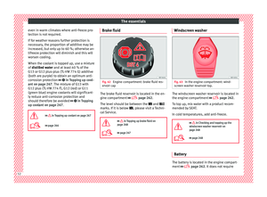
Fig. 236
Schematic diagram: assignment of
the pins of
the trailer's electrical socket.
Key of the Schematic diagram ››› Fig. 236:
PinMeaning
1Left turn signal
2Rear fog light
3Earth, pins 1, 2, 4 to 8
4Right turn signal
5Rear light, right
6Brake lights
7Rear light, left
8Reverse lights
9Permanent live
10Cable without positive charge
11Earth, pin 10
Key of the Schematic diagram ››› Fig. 236:
PinMeaning
12Unassigned
13Earth, pin 9 Electrical socket for trailer
The v
ehic
le is fitted with a 13-pole power
socket for the electrical connection between
the trailer and the vehicle. If the system de-
tects that a trailer has been connected elec-
trically, the electrical equipment on the trailer
will receive voltage through this connection.
Pin 9 has a permanent live. This powers, for
example, the trailer's interior lighting. Pin 10
is only powered when the engine is running.
The charge wire (pin 10) charges, for exam-
ple, a caravan battery.
Pin 9 and 10 should not be connected to
each other to avoid discharging or damaging
the vehicle's battery.
The earth wires, pin 3, pin 11 and pin 13,
should never be connected to each other to
avoid overloading the electrical system.
If the trailer has a 7-contact connector , you
will need to use an adapter cable. In this case
the function corresponding to pin 10 will not
be available.
240
Page 243 of 324

Towing bracket device
Trailer maximum electricity consumptionBrake lights (total)84 Watts
Turn signal, on each side42 Watts
Side lights (total)100 Watts
Rear lights (total)42 Watts
Rear fog light42 Watts
Never exceed the values indicated! Note
● If the r e
ar lights of the trailer are not cor-
rectly connected, the vehicle electronics may
be damaged.
● If the trailer absorbs excessive electric cur-
rent, the v
ehicle electronics may be dam-
aged.
● Never connect the trailer's electric system
directly t
o the electrical connections of the
tail lights or any other power sources. Only
use the connections intended for providing
electric current to the trailer. Ball coupling of towing bracket de-
v
ic
e* The ball coupling is provided with instruc-
tions
on fittin
g and removing the ball cou-
pling of the towing bracket. WARNING
The towing bracket ball coupling must be
st or
ed securely in the luggage compartment
to prevent them being flung through the vehi-
cle and causing injury. Note
● By l
aw, the ball coupling must be removed
if a trailer is not being towed if it obscures
the number plate. Driving with a trailer
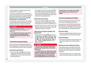
Fig. 237
Turn the 13-pin connector Before driving
● Grip the 13-pin connector at area A and
r emo
v
e it in the direction of the arrow
››› Fig. 237.
● Remove the protective cover 5
› ›
› Fig. 225
up
wards.
After driving
● Grip the 13-pin connector at area A and
in ser
t
it in the opposite direction to the arrow
››› Fig. 237.
● Fit the protective cover 5
› ›
›
Fig. 225 on
the ball coupling. »
241
Technical data
Advice
Operation
Emergencies
Safety
Page 244 of 324

Operation
Safety lug
The s af
ety
lug B
› ››
Fig. 237
i
s used to hook
up the trailer's retainer cable.
On hooking it up to the safety lug, the retain-
er cable should have slack in all the trailer
positions with respect to the vehicle (sharp
bends, reverse gear, etc.).
Headlights
The front part of the vehicle may be raised
when the trailer is connected and the light
may dazzle the rest of the traffic.
Adapt the height of the headlights using the
headlight range rotary adjuster 1)
. WARNING
● Never u se the s
afety lug to tow!
● Adjust your speed to suit the road and traf-
fic condition
s.
● All work on the electrical system must be
carried out on
ly by specialised workshops.
● Never connect the trailer's electric system
to the electric
al connections of the rear lights
or any other power sources.
● After hooking up the trailer and connecting
the socket, c
heck that all the trailer's rear
lights are working properly. Note
● If ther e i
s any fault in the trailer's lighting,
check the fuses in the instrument panel fuse
box ›››
page 54.
● The contact between the retainer cable and
the safety
lug may give rise to mechanical
wear in the lug's surface protection. This
wear will not prevent the safety lug from op-
erating properly or cause any fault and is ex-
cluded from the warranty.
● When connecting and disconnecting the
trail
er, the towing vehicle's handbrake
should be applied. Anti-theft alarm system
When the vehicle is locked, the alarm is trig-
g
er
ed when the el
ectrical connection be-
tween vehicle and trailer is interrupted.
Always turn off the anti-theft alarm system
before connecting or disconnecting a trailer
››› page 124.
Conditions for the integration of a trailer in
the anti-theft alarm system.
● The vehicle is factory-equipped with an an-
ti-theft al
arm system and a towing bracket
device. ●
The trail
er is connected electrically to the
towing vehicle by the trailer connector.
● The electrical system of the vehicle and the
trail
er are prepared for operation.
● The vehicle is locked with the ignition key
and the anti-theft al
arm system is activated. CAUTION
For technical reasons, trailers fitted with rear
LED lights ar
e not integrated in the anti-theft
alarm system. Driving tips
Driving with a trailer always requires extra
c
ar
e.
W
eight distribution
The weight distribution of a loaded trailer
with an unladen vehicle is very unfavourable.
However, if this cannot be avoided, drive ex-
tra slowly to allow for the unbalanced weight
distribution.
Speed
The stability of the vehicle and trailer is re-
duced with increasing speed. For this reason,
it is advisable not to drive at the maximum 1)
This does not apply for vehicles with bi-xenon
hea dlights.
242
Page 245 of 324

Towing bracket device
permissible speed in an unfavourable road,
w e
ather or w
ind conditions. This applies es-
pecially when driving downhill.
You should always reduce speed immediately
if the trailer shows the slightest sign of snak-
ing. Never try to stop the “snaking” by in-
creasing speed.
Always brake in due course. If the trailer has
an overrun brake, apply the brakes gently at
first and then, firmly. This will prevent the
jerking that can be caused by locking of trail-
er wheels. Select a low gear in due course
before going down a steep downhill. This en-
ables you to use the engine braking to slow
down the vehicle.
Reheating
At very high temperatures and during pro-
longed slopes, driving in a low gear and high
engine speed, always monitor the coolant
temperature gauge ››› page 109.
Electronic stability control*
The ESC* system helps to stabilise the trailer
in case of skidding or rocking. Retrofitting a towing bracket*
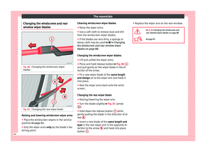
Fig. 238
Attachment points for towing brack-
et . If a towing bracket is to be fitted after the ve-
hic
l
e i
s purchased, this must be completed
according to the instructions of the towing
bracket manufacturer. The attachment points for the towing bracket
A are on the lower part of the vehicle.
The di s
t
ance between the centre of the ball
coupling and the ground should never be
lower than the indicated value, even with a
fully loaded vehicle and including the maxi-
mum drawbar load.
Elevation values for securing the towing
bracket:
B65 mm (minimum)
C350 mm to 420 mm (fully laden vehicle)
D1040 mm
E317 mm
FLEON/LEON SCLEON ST
319 mm596 mm Fitting a towing bracket
●
Driving with a trailer involves an extra effort
f or the
v
ehicle. Therefore, before fitting a
towing bracket, please contact a Technical
Service to check whether your cooling system
needs modification.
● The legal requirements in your country
must
be observed (e.g. the fitting of a sepa-
rate control lamp).
● Certain vehicle components, e.g. the rear
bumper, mu
st be removed and reinstalled.
The towing bracket securing bolts must be »
243
Technical data
Advice
Operation
Emergencies
Safety
Page 246 of 324

Operation
tightened using a torque wrench, and a pow-
er soc k
et
must be connected to the vehicle
electrical system. This requires specialised
knowledge and tools.
● Figures in the illustration show the eleva-
tion value and the att
achment points which
must be considered if you are retrofitting a
towing bracket. WARNING
The towing brackets should be fitted at a spe-
ci a
lised workshop.
● If the towing bracket is incorrectly instal-
led, there i
s a serious danger of accident.
● For your own safety, please observe the tow
brack
et manufacturer's instructions. CAUTION
● If the po w
er socket is incorrectly installed,
this could cause damage to the vehicle elec-
trical system. Note
● SEA T r
ecommends that the towing hooks
be fitted at a specialised workshop. Consult
your SEAT dealer in case additional modifica-
tions to your vehicle are necessary.
● Due to the specific design of the exhaust,
the fitting of a c
onventional towing hook is
not recommended for some sportier versions.
Please consult your Technical Service. 244
Page 247 of 324

Care and maintenance
Advice
C ar
e and m
aintenance
Accessories and modifications to the vehicle
Accessories, replacement parts and
repair work Always ask your dealer or specialist retailer
f
or a
dv
ice before purchasing accessories and
replacement parts.
Your vehicle is designed to offer a high
standard of active and passive safety. For this
reason, we recommend that you ask a SEAT
Official Service for advice before fitting ac-
cessories or replacement parts. Your SEAT Of-
ficial Service has the latest information from
the manufacturer and can recommend acces-
sories and replacement parts which are suita-
ble for your requirements. They can also an-
swer any questions you might have regarding
official regulations.
We recommend you to use only SEAT acces-
sories and Genuine SEAT parts ®
. SEAT has
tested these parts and accessories for suita-
bility, reliability and safety. SEAT Official
Services have the necessary experience and
facilities to ensure that the parts are installed
correctly and professionally. Any
retro-fitted equipment which has a direct
effect
on the vehicle and/or the way it is driv-
en, such as a cruise control system or elec-
tronically-controlled suspension, must be
approved for use in your vehicle and bear the
e mark (the European Union's authorisation
symbol).
If any additional electrical devices are fitted
which do not serve to control the vehicle it-
self (for instance a refrigerator box, laptop or
ventilator fan, etc.), they must bear the
sign (manufacturer conformity declaration in
the European Union). WARNING
Accessories, for example telephone holders
or cup ho l
ders, should never be fitted on the
covers, or within the working range of the air-
bags. Otherwise, there is a danger of injury if
the airbag is triggered in an accident. Modifications
Modifications must always be carried out ac-
c
or
din
g to our specifications.
Unauthorised modifications to the electronic
components, software, wiring or data transfer
in the vehicle may cause malfunctioning. Due
to the way the electronic components are
linked together in networks, other indirect
systems may be affected by the faults. This
can seriously impair safety, lead to excessive wear of components, and also invalidate your
vehicl
e registration documents.
You will appreciate that your SEAT dealership
cannot be held liable for any damage caused
by modifications and/or work performed in-
correctly.
We therefore recommend that all work should
be performed by a SEAT Official Service using
genuine SEAT parts ®
. WARNING
Incorrectly performed modifications or other
work on
your vehicle can lead to malfunctions
and cause accidents. Radio transmitters and office equip-
ment
Radio transmitters (fixed installation)
An
y
r
etrofit installations of radio transmitters
in the vehicle require prior approval. SEAT
generally authorises in-vehicle installations
of approved types of radio transmitters provi-
ded that:
● The aerial is installed correctly.
● The aerial is installed on the exterior of the
vehicl
e (and shielded cables are used togeth-
er with non-reflective aerial trimming).
● The effective transmitting power does not
exc
eed 10 Watts at the aerial base. »
245
Technical data
Advice
Operation
Emergencies
Safety
Page 248 of 324

Advice
A SEAT Official Service and specialised work-
shop w i
l
l be able to inform you about options
for installing and operating radio transmitters
with a higher transmitting power.
Mobile radio transmitters
Commercial mobile telephones or radio
equipment might interfere with the electron-
ics of your vehicle and cause malfunctions.
This may be due to:
● No external aerial.
● External aerial incorrectly installed.
● Transmitting power more than 10 W.
You mus
t, therefore, do not operate portable
mobile telephones or radio equipment inside
the vehicle without a properly installed exter-
nal aerial ››› .
Pl e
a
se note also that the maximum range of
the equipment can only be achieved with an
external aerial.
Business equipment
Retrofit installation of business or private
equipment in the vehicle is permitted, provi-
ded the equipment cannot interfere with the
driver's immediate control of the vehicle and
that any such equipment carries the mark.
Any retrofit equipment that could influence
the driver's control of the vehicle must have a
type approval for your vehicle and must carry
the e mark. WARNING
Mobile telephones or radio equipment which
is oper
ated inside the vehicle without a prop-
erly installed external aerial can create exces-
sive magnetic fields that could cause a health
hazard. Note
● The pos t
erior fitting of electric and elec-
tronic equipment in this vehicle affects its li-
cence and could lead to the withdrawal of the
vehicle registration document under certain
circumstances.
● Please use the mobile telephone/radio op-
erating in
structions. Care and cleaning
Gener a
l
information Regular and careful care helps to
maint
ain
the
value of the vehicle. This may also be one
of the requirements for upholding any war-
ranty claims in the event of corrosion or paint
defects.
SEAT Official Services and specialist retailers
carry stocks of suitable car care materials.
Please follow the instructions for use on the
packaging. WARNING
● Cle
aning products and other materials used
for car care can be damaging to your health if
misused.
● Always keep care products in a safe place,
out of the r
each of children. Failure to comply
could result in poisoning. For the sake of the environment
● If po s
sible, use environmentally friendly
products.
● The remains of car care products should not
be dispo
sed of with ordinary household
waste. Vehicle exterior care
W a
shin
g the vehicle The longer substances such as insects, bird
dr
op
pin
gs, resinous tree sap, road dirt, in-
dustrial deposits, tar, soot or road salt and
other aggressive materials remain on the ve-
hicle, the more damage they do to the paint-
work. High temperatures (for instance due to
strong sunlight) further intensify the corro-
sive effect.
After the period when salt is put on the roads
it is important to have the underside of the
vehicle washed thoroughly.
246